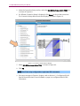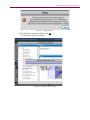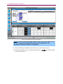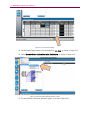
1
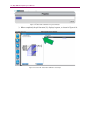
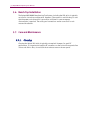
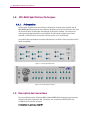
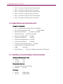
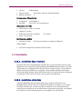
MB5 MIMO
Beamforming Test System
User Manual
Spirent
541 Industrial Way West
Eatontown, NJ 07724 USA
Email: [email protected]
Web: http://www.spirent.com
AMERICAS 1-800-SPIRENT • +1-818-676-2683 • [email protected]
EUROPE AND THE MIDDLE EAST +44 (0) 1293 767979 • [email protected]
ASIA AND THE PACIFIC +86-10-8518-2539 • [email protected]
This manual applies to MB5 MIMO Version 1.20 or higher.
Page Part Number: 71-006794, Version A1
Copyright © 2012 Spirent. All Rights Reserved.
All of the company names and/or brand names and/or product names referred to in this document, in particular, the
name “Spirent” and its logo device, are either registered trademarks or trademarks of Spirent plc and its
subsidiaries, pending registration in accordance with relevant national laws. All other registered trademarks or
trademarks are the property of their respective owners.
The information contained in this document is subject to change without notice and does not represent a
commitment on the part of Spirent. The information in this document is believed to be accurate and reliable;
however, Spirent assumes no responsibility or liability for any errors or inaccuracies that may appear in the
document.
Safety Summary
If the equipment is used in a manner not specified by the manufacturer the protection provided by the
equipment may be impaired.
Safety Symbols
The following safety symbols are used throughout this manual and may be found on the instrument.
Familiarize yourself with each symbol and its meaning before operating this instrument.
Instruction manual symbol. The
product is marked with this symbol
when it is necessary for you to refer
to the instruction manual to protect
against damage to the instrument.
Protective ground (earth) terminal.
Used to identify any terminal which
is intended for connection to an
external protective conductor for
protection against electrical shock in
case of a fault, or to the terminal of a
protective ground (earth) electrode.
Indicates dangerous voltage
(terminals fed from the interior by
voltage exceeding 1000 volts must
be so marked).
Frame terminal. A connection to
the frame (chassis) of the
equipment which normally
includes all exposed metal
structures.
The caution sign denotes a
hazard. It calls attention to an
operating procedure, practice,
condition or the like, which, if
not correctly performed or
adhered to, could result in
damage to or destruction of
part or all of the product or your
data.
Alternating current (power line).
Résumé des règles de sécurité
Si le matériel est utilisé d’une façon non conforme aux spécifications du constructeur, la protection assurée
par le matériel peut être mise en défaut.
Symboles de sécurité
Les symboles suivants sont utilisés dans tout le manuel et peuvent être trouvés sur le matériel. Il est
recommandé de se familiariser avec chaque symbole et sa signification avant de manipuler le matériel.
Symbole « manuel d’instruction ». Ce
symbole apparaît sur le produit
lorsqu’il est nécessaire de se référer
au manuel d’instruction pour éviter
une détérioration du matériel.
Terre : ce symbole identifie la
connexion de terre chargée de
protéger le matériel contre les chocs
électriques. Cette connexion doit
être raccordée vers un conducteur
externe de protection ou vers une
électrode de type terre.
Ce symbole indique un voltage
dangereux (connexion alimentée en
interne par un voltage excédant
1000 volts).
Masse. Ce symbole identifie
une connexion au châssis du
matériel (ce châssis inclut
normalement toutes les
structures métalliques
exposées).
Ce symbole désigne une
opération ou une condition dite
« sensible », qui, si elle n’est
pas correctement réalisée,
pourrait entraîner de sérieuses
détériorations au matériel ou
aux données utilisateur.
Courant alternatif (ligne de
puissance).
Table of Contents
1. Introduction .......................................................................................... 1
1.1.
Overview ........................................................................................... 1
2. Setting Up the Test System ................................................................... 3
2.1.
Overview ........................................................................................... 3
2.2.
Connections and Power ...................................................................... 4
2.3.
Ventilation ......................................................................................... 5
3. Configuring the Test System ................................................................. 6
3.1.
Overview ........................................................................................... 6
3.2.
Configuring IP Addresses of Test Equipment ....................................... 7
3.2.1. Configuring the Primary VR5 ................................................................... 7
3.2.2. Configuring the Secondary VR5............................................................... 9
3.2.3. Configuring the Network Analyzer ........................................................... 9
3.3.
Configuring VR5 HD Spatial Channel Emulator Control Software .......... 9
4. Using the Test System ........................................................................ 15
4.1.
4.2.
Overview ......................................................................................... 15
Phase Calibration............................................................................. 16
4.2.1. Initial Calibration, 8X2 BiDirectional...................................................... 16
4.2.2. 8X2 BiDirectional Automatic Calibration................................................ 27
4.3.
MB5 MIMO Beamforming Test System Specifications ........................ 29
5. Appendix: VR5-8600 Technical Specifications .................................... 30
5.1.
Overview ......................................................................................... 30
5.2.
5.3.
Connector Descriptions .................................................................... 31
RF Performance Specifications.......................................................... 32
5.4.
Interface and Environmental Characteristics ..................................... 32
5.5.
Rack Installation .............................................................................. 33
5.6.
Bench-Top Installation ..................................................................... 34
5.7.
Care and Maintenance ..................................................................... 34
5.7.1. Cleaning ............................................................................................... 34
5.8.
VR5-8600 Spécifications Techniques ................................................ 36
ii | MR5 MIMO Beamforming User Manual
5.8.1. Présentation ......................................................................................... 36
5.9.
Description des Connecteurs ............................................................ 36
5.10.
5.11.
Spécifications du Performance RF ................................................... 38
Interface et Caractéristiques d’environnement ................................ 38
5.12.
Installation .................................................................................... 39
5.12.1. Installation dans le Cabinet ................................................................. 39
5.12.2. Installation sur le Banc........................................................................ 39
5.13.
Entretien et Soin ............................................................................ 40
5.13.1. Nettoyage............................................................................................ 40
1. Introduction
1.1. Overview
This document provides detailed information on how to use the MB5 MIMO
Beamforming Test System.
The system consists of the following:
•
Two (2) VR5 Channel Simulators in an 8x2 bi directional MIMO configuration
•
One (1) VR5-8600 RF Interface Unit
•
One (1) Cisco switch
•
One (1) supporting laptop computer
•
One (1) Network Analyzer (user supplied)
The 8600 provides the capability for summing and/or splitting downlink and uplink RF
paths to enable bidirectional operation. The Beamforming Test System has eight RF ports
for connections to base station (NodeB), or network emulator antenna ports, and two RF
ports for connections to User Equipment (UE) antenna ports. The system is controlled by
a computer.
2 | MR5 MIMO Beamforming User Manual
Figure 1-1: 8x2 MIMO Beamforming Test System Rack
2. Setting Up the Test System
2.1. Overview
The Setup Guide (document Part Number: 71-006708) provides complete wiring
connections for the 8x2 MIMO configuration.
The system consists of the following components:
•
Two (2) VR5 Channel Simulators in an 8x2 bi directional MIMO configuration
•
One (1) VR5-8600 RF Interface Unit
•
One (1) Cisco switch
•
One (1) supporting laptop computer
•
One (1) Network Analyzer (user supplied)
An overview of the key connections is shown Figure 2-1.
Figure 2-1: Rack Connections
4 | MR5 MIMO Beamforming User Manual
2.2. Connections and Power
1. Ensure that all Ethernet, RF cables, and Sync cables are connected as shown in the
Setup Guide.
2. Turn on the rack. The power switch is located under an access door on the top right
of the rack, as shown in Figure 2-2.
Switch Access
Door Closed
Open
Figure 2-2: Rack Power Switch
3. Ensure that the rack exhaust fans are running. Wait three minutes for the SYST and
STAT LED to illuminate steady green on the Cisco switch.
4. Power-on the system in the following order:
a. VR5-8600
b. User-supplied Network Analyzer
c. VR5 Unit #1
d. VR5 Unit #2
e. Controller Laptop
5. Wait for the laptop operating system to load and log in.
6. Ensure that the laptop IP address is set to the 192.168.0.xxx subnet.
7. If the IP addresses for the VR5 instruments are not configured, follow the instructions
in Chapter 3. If the test setup is already configured, proceed to Chapter 4 on page
15.
Chapter Two: Setting Up the System | 5
2.3. Ventilation
For proper ventilation, ensure that the rack is located in an area with the following
conditions:
•
A minimum of eighteen (18) inches of space between the sides of the rack and any
objects that may restrict air flow. For example, a wall, cabinet, or another rack.
•
A minimum of twelve (12) inches of space between the rear door and any object that
may restrict air flow. For example, a wall, cabinet, or another rack.
•
Make sure there is nothing that blocks the airflow from the exhaust fans on the top
of the rack.
•
Do not allow other equipment to exhaust into the rack, as this may cause the
equipment to overheat.
•
If insufficient ventilation is provided, the equipment in the rack may overheat. This
can cause improper operation.
3. Configuring the Test System
3.1. Overview
This chapter describes the configuration of the MIMO Test System. It involves setting the
IP addresses of the primary and secondary VR5 units, and the user-supplied network
analyzer and then testing those connections using the VR5 Spatial Channel Emulator
software running on the control computer.
The network configuration is shown in Figure 3-1.
Figure 3-1: Network Configuration
Chapter Three: Configuring the Test System | 7
3.2. Configuring IP Addresses of Test Equipment
The following sections describe the IP address configuration for the test equipment
illustrated in Figure 3-1.
3.2.1.
Configuring the Primary VR5
1. Ensure the primary VR5 HD Spatial Channel Emulator is powered-on.
The VR5 Main window displays, as shown in Figure 3-2.
Figure 3-2: VR5 HD Spatial Channel Emulator Main Window
2. Using the touch screen interface, select the IP Address Setting button shown in
Figure 3-2.
The IP Address Setting window displays, as shown in Figure 3-3.
8 | MR5 MIMO Beamforming User Manual
Figure 3-3: IP Address Setting Window
3. In the IP Address field, enter 192.168.0.151.
4. Ensure that the Subnet Mask and Default Gateway settings are configured as shown
in Figure 3-3.
5. Click the Apply Settings button.
6. Click the Main button, as shown in Figure 3-4.
The VR5 Main window displays, as shown in Figure 3-2.
Figure 3-4: Selecting Main View on VR5
Chapter Three: Configuring the Test System | 9
3.2.2.
Configuring the Secondary VR5
Using the touch screen interface on the secondary VR5 unit, repeat the steps in the
Section 3.2.1 on page 7and enter the following settings:
•
IP Address: 192.168.0.152
•
Subnet Mask: 255.255.255.0
•
Default Gateway: 192.168.0.1
3.2.3.
Configuring the Network Analyzer
Set the IP address of the user-supplied Network analyzer to: 192.168.0.86.
Ensure that Telnet Server is enabled. Refer to the manufacturer documentation for the
network analyzer for further information.
3.3. Configuring VR5 HD Spatial Channel Emulator Control
Software
NOTE: Ensure that the control laptop IP address is set to 192.168.0.xxx subnet.
Figure 3-5: VR5 HD Spatial Channel Emulator Software Icon
1. On the Controller Laptop, launch the VR5 HD Spatial Channel Emulator control
software by clicking the icon shown in Figure 3-5.
The VR5 Spatial Channel Emulator Window displays, as shown in Figure 3-6.
10 | MR5 MIMO Beamforming User Manual
Figure 3-6: VR5 HD Spatial Emulator Start Window
2. In the Primary VR5 IP Address field, enter 192.168.0.151.
3. Click the Connect button.
4. The VR5 HD Main window displays, as shown in Figure 3-7.
Figure 3-7: VR5 HD Main Window
Chapter Three: Configuring the Test System | 11
5. To connect the secondary unit, select Configure>Additional VR5 Instruments, as
shown in Figure 3-8.
Figure 3-8: Configuring Additional VR5 Instruments
6. The Additional VR5 Instruments window displays, as shown in Figure 3-9.
Figure 3-9: Additional VR5 Instruments Window
7. In the Enter IP Address of Unit #2 field, enter the IP address of the secondary VR5
unit: 192.168.0.152.
8. Click Connect Now.
12 | MR5 MIMO Beamforming User Manual
9. A message displays, as shown in Figure 3-10.
Figure 3-10: Connecting to Secondary Instrument Message
10. When the connection is successfully completed, the Additional VR5 Instruments
window displays, as shown in Figure 3-11.
Figure 3-11: Additional VR5 Instruments
11. Click Close.
Chapter Three: Configuring the Test System | 13
12. Connect the user-supplied network analyzer by selecting Execute>Phase
Calibration>Network Analyzer Setting, as shown in Figure 3-12.
Figure 3-12: Connecting the Network Analyzer
13. The Network Analyzer Settings window displays, as shown in Figure 3-13.
Figure 3-13: Network Analyzer Settings Window
14. In the Choose Model field, select your network analyzer from the menu. This example
uses the Agilent Technologies: E5071C, a message displays, as shown in Figure
3-14.
14 | MR5 MIMO Beamforming User Manual
Figure 3-14: Network Analyzer Test Success Message
15. Click OK.
16. The VR5 HD Main window displays, as shown in Figure 3-15.
Figure 3-15: VR5 HD Main Window
The MB5 MIMO Beamforming Test System is now configured for use.
4. Using the Test System
4.1. Overview
Figure 4-1 shows the functional block diagram of the 8x2 Beamforming Test System.
Figure 4-1: 8x2 Beamforming Test System Diagram
16 | MR5 MIMO Beamforming User Manual
4.2. Phase Calibration
The phase calibration procedure includes two parts:
1. Initial: Calibrates the cables used in the test setup. After this procedure is
performed, it does not have to be repeated as long as the cables are not changed.
2. Automatic: Must be performed before each selected test.
The following sections describe Initial and Automatic Calibration for the 8 x 2
BiDirectional configuration.
4.2.1.
Initial Calibration, 8X2 BiDirectional
NOTE: You must perform the Initial Calibration each time cables in the test setup are
changed.
1. On the Control laptop, launch the VR5 HD Spatial Channel Emulator control software
by clicking the icon shown in Figure 4-2.
Figure 4-2: VR5 HD Spatial Channel Emulator Software Icon
2. The VR5 HD Spatial Emulator Start window displays, as shown in Figure 4-3.
Chapter Four: Using the Test System |-17
Figure 4-3: VR5 HD Spatial Emulator Start Window
3. Click Connect.
4. The VR5 HD Main window displays, as shown in Figure 4-4.
Figure 4-4: VR5 HD Main Window
18 | MR5 MIMO Beamforming User Manual
5. Under the Connection Setup section, select the 8X2 BiDirectional–8600 (TDD) test,
as shown in Figure 4-4.
6. If a different Connection Setup is displayed, click Select to choose the correct test.
The Connection Setup Selection window displays, as shown in Figure 4-5.
Figure 4-5: Connection Setup Selection Window
7. Select 8X2 BiDirectional-8600 (TDD), as shown in Figure 4-5.
8. Click OK.
NOTE: Not all test setup configurations require two VR5 instruments.
9. If the error message in Figure 4-6 displays, refer to Section 3.3, Configuring VR5 HD
Spatial Channel Emulator Control Software on page 9 to configure additional VR5
instruments.
Chapter Four: Using the Test System |-19
Figure 4-6: Configuration Error
10. If everything is properly configured click OK.
The message in Figure 4-7 displays.
Figure 4-7: Loading Connection Setup
20 | MR5 MIMO Beamforming User Manual
Figure 4-8: Main Window Upon Setup Completion
NOTE: In the Connection Setup diagram shown in Figure 4-8, the phi character (Φ) is
red. This indicates that the Automatic calibration must be performed. This
procedure is described in Section 4.2.2 on page 27.
11. Under the RF Setup and Measurement section, go to the Output columns.
12. Under the Set Power column, change the power level to -25 dBm for Port B1 and B2,
as shown in Figure 4-9.
Chapter Four: Using the Test System |-21
Figure 4-9: Set Power for Initial Calibration
13. Under Unit No., click the down arrow, as shown in Figure 4-10 to display the settings
for VR5 unit 2.
Figure 4-10: Unit Number Up and Down Arrow
14. The settings for Unit 2 display, as shown in Figure 4-11.
22 | MR5 MIMO Beamforming User Manual
Figure 4-11: Unit 2 Power Settings
15. Set the Power Output Levels for A1 through A8 to -25 dBm, as shown in Figure 4-11.
16. Select Execute>Phase Calibration>Initial Calibration, as shown in Figure 4-12.
Figure 4-12: Execute Initial Calibration Menu Location
17. The Initial Phase Calibration window displays, as shown in Figure 4-13.
Chapter Four: Using the Test System |-23
Figure 4-13: Initial Phase Calibration Window
18. Click Next.
The message in Figure 4-14 displays.
24 | MR5 MIMO Beamforming User Manual
Figure 4-14: Initial Calibration Progress Indicator
19. When the test initialization is complete, a Connection Setup window displays, as
shown in Figure 4-15.
Chapter Four: Using the Test System |-25
Figure 4-15: Connection Setup Window
20. Perform the Instructions given in the Connection Setup window and click Next, as
shown in Figure 4-15.
21. The results of the measurement in the previous step displays, as shown in Figure
4-16.
Figure 4-16: Connection Setup – Measurement Result
22. Perform the steps listed in Figure 4-16 and click Next.
26 | MR5 MIMO Beamforming User Manual
23. Repeat this process for every cable connection in the test setup.
NOTE: The cable connected to Port 1 of the Network Analyzer is used in the
calibration process for the NodeB portions of the test. The cable connected to Port 2
is used for the NodeA portions of the test.
24. Follow the steps described in the Connection Setup windows until the Initial Phase
Calibration window displays, as shown in Figure 4-17.
Figure 4-17: Initial Phase Calibration Window
25. Click Close to return to the VR5 HD Main window.
Chapter Four: Using the Test System |-27
4.2.2.
8X2 BiDirectional Automatic Calibration
NOTE: In the Connection Setup diagram shown in Figure 4-8, the phi character (Φ) is
red. This indicates that the Automatic calibration must be performed. This
procedure is described in Section 4.2.2 on page 27.
Figure 4-18: Red Φ Indicator Location (Automatic Calibration Required)
1. Select Execute>Phase Calibration>Single Calibration, as shown in Figure 4-18.
Figure 4-19: Automatic Calibration Menu Location
2. A Progress indicator displays, as shown in Figure 4-20.
28 | MR5 MIMO Beamforming User Manual
Figure 4-20: Automatic Calibration Progress Indicator
3. When completed, the phi character (Φ) displays in green, as shown in Figure 4-21.
Figure 4-21: Green Φ – Automatic Calibration Successful
Chapter Four: Using the Test System |-29
4.3. MB5 MIMO Beamforming Test System Specifications
The list below provides a summary of Beamforming Test System Specifications.
Frequency Range: 700-2700 MHz
Typical RF Path Loss (from NodeB connection on VR5-8600 to VR5 input or output): 6
dB at 2700 MHz
Typical RF Path Loss (from UE connection on VR5-8600 to VR5 input or output):
6 dB at 2700 MHz
Damage Input Power Levels:
•
Maximum Input Power into any NodeB Port: 33 dBm
•
Maximum Input Power into any UE Port: 33 dBm
Input Power Level Ranges for Proper Operation:
•
Operational Input Power into any NodeB Port: -35 to 20 dBm
•
Operational Input Power into any UE Port: -35 to 20 dBm
Typical Output Power Level Ranges in Proper Operation:
•
Typical Operational Output Power from any NodeB Port: -116 to -30 dBm
•
Typical Operational Output Power from any UE Port: -116 to -30 dBm
5. Appendix: VR5-8600 Technical Specifications
5.1. Overview
The Spirent VR5-8600 is a test configuration unit that is used with the Spirent MB5
MIMO Beamforming Test System. Its purpose is to provide RF measurement paths for the
auto-phase calibration of the system. The auto-phase calibration measurements are
performed using a vector network analyzer. The VR5-8600 is remotely controlled with a
PC over Ethernet.
The following technical specifications describe the conditions under which the VR5-8600
is operated.
VR5-8600
CONTROLLER
I/O
I/O
NodeB
1
NodeB
7
I/O
NodeB
5
I/O
NodeB
4
I/O
I/O
I/O
NodeB
3
I/O
NodeB
8
UE
3
I/O
UE
2
I/O
POWER
I/O
Cal
2
NodeB
6
NodeB
2
I/O
SYSTEM
Cal
1
I/O
I/O
UE
1
I
UE
4
O
Figure 5-1: Front Panel View
VR5-8600
RP23
RP21
RP19
RP17
RP15
RP13
RP11
RP9
RP7
RP5
RP3
RP1
RP24
RP22
RP20
RP18
RP16
RP14
RP12
RP10
RP8
RP6
RP4
RP2
USER
CONNECT
AUX
Figure 5-2: Rear Panel View
Chapter Five: Appendix |-31
5.2. Connector Descriptions
For use with the Spirent MB5 MIMO Beamforming Test System that supports 8x4, 8x2,
and 4x2 antenna arrays. The VR5-8600 RF connector configurations are provided below.
Front Panel RF Connections:
•
NodeB 1 – Connects to port 1 of the NodeB antenna array
•
NodeB 2 – Connects to port 2 of the NodeB antenna array
•
NodeB 3 – Connects to port 3 of the NodeB antenna array
•
NodeB 4 – Connects to port 4 of the NodeB antenna array
•
NodeB 5 – Connects to port 5 of the NodeB antenna array; (for 8x4 and 8x2 systems
only)
•
NodeB 6 – Connects to port 6 of the NodeB antenna array; (for 8x4 and 8x2 systems
only)
•
NodeB 7 – Connects to port 7 of the NodeB antenna array; (for 8x4 and 8x2 systems
only)
•
NodeB 8 – Connects to port 8 of the NodeB antenna array; (for 8x4 and 8x2 systems
only)
•
Cal 1 – Connects to Port 1 of the vector network analyzer
•
Cal 2 – Connects to Port 2 of the vector network analyzer
•
UE 1 – Connects to the UE antenna terminal #1
•
UE 2 – Connects to the UE antenna terminal #2
•
UE 3 – Connects to the UE antenna terminal #3; (for 8x4 systems only)
•
UE 4 – Connects to the UE antenna terminal #4; (for 8x4 systems only)
Rear Panel RF Connections:
•
RP1 – Connection to VR5 for downlink
•
RP2 – Connection from VR5 for uplink
•
RP3 – Connection to VR5 for downlink
•
RP4 – Connection from VR5 for uplink
•
RP5 – Connection to VR5 for downlink
•
RP6 – Connection from VR5 for uplink
•
RP7 – Connection to VR5 for downlink
•
RP8 – Connection from VR5 for uplink
•
RP9 – Connection to VR5 for downlink
•
RP10 – Connection from VR5 for uplink
•
RP11 – Connection to VR5 for downlink
32 | MR5 MIMO Beamforming User Manual
•
RP12 – Connection from VR5 for uplink
•
RP13 – Connection to VR5 for downlink
•
RP14 – Connection from VR5 for uplink
•
RP15 – Connection to VR5 for downlink
•
RP16 – Connection from VR5 for uplink
•
RP17 – Connection from VR5 for downlink
•
RP18 – Connection to VR5 for uplink
•
RP19 – Connection from VR5 for downlink
•
RP20 – Connection to VR5 for uplink
•
RP21 – Connection from VR5 for downlink
•
RP22 – Connection to VR5 for uplink
•
RP23 – Connection from VR5 for downlink
•
RP24 – Connection to VR5 for uplink
5.3. RF Performance Specifications
Frequency Range:
•
Cal 1 to any Node B port
•
Cal 2 to any UE port
•
Node B ports to RP ports
•
UE ports to RP ports
400 MHz to 4000 MHz
•
Max RF Input Power
+30 dBm
•
Isolation between RP Ports
•
Isolation between Node B ports
•
Isolation between UE ports
•
Isolation between Cal and Node B ports
•
Isolation between Cal and UE ports
•
VSWR
•
Insertion Loss Varies with frequency and selected path
DC to 4000 MHz
DC to 4000 MHz
400 MHz to 4000 MHz
18 dB Min
80 dB Min
80 dB Min
80 dB Min
80 dB Min
1.60:1 Max
5.4. Interface and Environmental Characteristics
Front Panel Indicators:
•
System 1 LED
•
Controller
1 LED
Chapter Five: Appendix |-33
Power Requirements:
•
Voltage 100-240 VAC (auto sensing)
•
Frequency
50-60 Hz
Power:
•
100 Vac
18 Watts (Max)
•
120 Vac
19 Watts (Max)
•
240 Vac
35 Watts (Max)
•
Fuse Type
2A, 250Vac, 5x20mm, Time Lag (Slo-Blo)
•
Number of Fuses
2
Operating Environment:
•
Temperature
0 to 40 degrees C
•
Humidity
10% to 90%, noncondensing
Dimensions and Weight:
•
Height (including feet) 5.9 inches
•
Width 17.2 inches
•
Depth (including handles)
•
Weight 31.5 pounds
22.9 inches
Control Interfaces:
•
Interfaces Provided
•
RJ-45 Jack on rear panel for RS-232 AUX
RJ-45 Jack on rear panel for Ethernet USER CONNECT
5.5. Rack Installation
The Spirent VR5-8600 is typically installed in an instrument rack along with the other
equipment that makes up the Spirent MB5 MIMO Beamforming Test System. For more
information about preparing the VR5-8600 for rack mounting, please refer to the Setup
Guide that applies to your specific system and the instruction sheet MI5574 supplied
with the VR5-8600 rack mount kit. The instructions for cabling and connecting the VR58600 are provided in the setup guide.
34 | MR5 MIMO Beamforming User Manual
5.6. Bench-Top Installation
The Spirent MB5 MIMO Beamforming Test System, including the VR5-8600, is typically
not used in a bench-top configuration. However, if the system is used this way, be sure
that the power-cord connection is accessible at all times in case emergency
disconnection is required. The cabling and connections are the same as for a rack
mounted installation.
5.7. Care and Maintenance
5.7.1.
Cleaning
Cleaning the Spirent VR5-8600 is typically not required. However, for good RF
performance, it is important to keep the RF connectors on the front and rear panels free
of dust and debris. Also, do not block the air exhaust vent on the rear panel.
Chapter Five: Appendix |-35
VR5-8600 Fuse Replacement Procedure
The fuse is installed at the factory to match the most commonly used line voltage in the
country of destination.
CAUTION: Disconnect from the supply before servicing
1. Locate the power entry module on rear panel.
2. Using a small screwdriver, pry out the fuse holder using the notch at the top of the
power entry module. Refer to diagram below.
3. Pull the fuse from the fuse holder as shown above.
4. To reinstall, select the proper fuse and place in the fuse holder.
Part Number
Type
1800-3703
2A 250V Slow-Blow Fuse
5. Reinsert the fuse holder into the power entry module.
36 | MR5 MIMO Beamforming User Manual
5.8. VR5-8600 Spécifications Techniques
5.8.1.
Présentation
Le VR5-8600 de Spirent est une unité de configuration de teste qui est utilisé avec le
MB5 MIMO Beamforming teste des systèmes de Spirent. Son but est de fournir des voies
de mesure RF pour l'étalonnage automatique de phase du système. Les mesures de
calibrage automatique de phase sont réalisées en utilisant un analyseur de réseau
vectoriel. Le VR5-8600 est commandé à distance avec un PC via Ethernet.
Les spécifications techniques suivantes décrivent les conditions dans lesquelles le VR58600 est exploité.
VR5-8600
CONTROLLER
I/O
NodeB
3
I/O
NodeB
1
NodeB
7
I/O
NodeB
5
I/O
NodeB
4
I/O
I/O
I/O
NodeB
8
UE
3
I/O
UE
2
I/O
POWER
I/O
Cal
2
NodeB
6
NodeB
2
I/O
SYSTEM
Cal
1
I/O
I/O
UE
1
I/O
I
UE
4
O
Figure 5-3: Vue du panneau avant
VR5-8600
RP23
RP21
RP19
RP17
RP15
RP13
RP11
RP9
RP7
RP5
RP3
RP1
RP24
RP22
RP20
RP18
RP16
RP14
RP12
RP10
RP8
RP6
RP4
RP2
USER
CONNECT
AUX
Figure 5-4: Vue du panneau arrière
5.9. Description des Connecteurs
Pour une utilisation avec le Spirent MB5 système MIMO Beamforming test qui prend en
charge les réseaux d'antennes 8x4, 8x2 et 4x2, les connecteurs VR5-8600 RF sont
configurés de la manière suivante:
Connexions du panneau avant RF:
Chapter Five: Appendix |-37
•
NodeB 1 – Connecte au port 1 de la NodeB réseau d’antenne
•
NodeB 2: Connecte au port 2 de la NodeB réseau d’antenne
•
NodeB 3: Connecte au port 3 de la NodeB réseau d’antenne
•
NodeB 4: Connecte au port 4 de la NodeB réseau d’antenne
•
NodeB 5: Connecte au port 5 de la NodeB réseau d’antenne; 8x4 and 8x2 systèmes
seulement
•
NodeB 6: Connecte au port 6 de la NodeB réseau d’antenne; 8x4 and 8x2 systèmes
seulement
•
NodeB 7: Connecte au port 7 de la NodeB réseau d’antenne; 8x4 and 8x2 systèmes
seulement
•
NodeB 8: Connecte au port 8 de la NodeB réseau d’antenne; 8x4 and 8x2 systèmes
seulement
•
Cal 1: Connecte au Port 1 de l'analyseur de réseau vectoriel
•
Cal 2: Connecte au Port 2 de l'analyseur de réseau vectoriel
•
UE 1: Connecte au UE du terminal de l’antenne #1
•
UE 2: Connecte au UE du terminal de l’antenne #2
•
UE 3: Connecte au UE du terminal de l’antenne #3; 8x4 systèmes seulement
•
UE 4: Connecte au UE du terminal de l’antenne #4; 8x4 systèmes seulement
Arrière connexions RF du panel:
•
RP1 – Connection au VR5 pour liaison descendante
•
RP2 – Connection de VR5 pour liaison montante
•
RP3 – Connection au VR5 pour liaison descendante
•
RP4 – Connection de VR5 pour liaison montante
•
RP5 – Connection au VR5 pour liaison descendante
•
RP6 – Connection de VR5 pour liaison montante
•
RP7 – Connection au VR5 pour liaison descendante
•
RP8 – Connection de VR5 pour liaison montante
•
RP9 – Connection au VR5 pour liaison descendante
•
RP10 – Connection de VR5 pour liaison montante
•
RP11 – Connection au VR5 pour liaison descendante
•
RP12 – Connection de VR5 pour liaison montante
•
RP13 – Connection au VR5 pour liaison descendante
•
RP14 – Connection de VR5 pour liaison montante
•
RP15 – Connection au VR5 pour liaison descendante
•
RP16 – Connection de VR5 pour liaison montante
•
RP17 – Connection de VR5 pour liaison descendante
•
RP18 – Connection au VR5 pour liaison montante
38 | MR5 MIMO Beamforming User Manual
•
RP19 – Connection de VR5 pour liaison descendante
•
RP20 – Connection au VR5 pour liaison montante
•
RP21 – Connection de VR5 pour liaison descendante
•
RP22 – Connection au VR5 pour liaison montante
•
RP23 – Connection de VR5 pour liaison descendante
•
RP24 – Connection au VR5 pour liaison montante
5.10.Spécifications du Performance RF
Gamme de frequencies:
•
Cal 1 à n’importe quel port de Node B DC à 4000 MHz
•
Cal 2 à n’importe quel port d’UE
•
Node B ports à RP ports
•
UE ports à RP ports
•
Puissance d’entrée max RF
+30 dBm
•
Isolement entre RP Ports
18 dB Min
•
Isolement entre Node B ports 80 dB Min
•
Isolement entre UE ports
•
Isolement entre Cal et Node B ports
•
Isolement entre Cal et UE ports 80 dB Min
•
VSWR
•
Perte d’insertion
DC à 4000 MHz
400 MHz à 3000 MHz
400 MHz à 3000 MHz
80 dB Min
80 dB Min
1.60:1 Max
Varie avec la fréquence et le chemin sélectionné
5.11.Interface et Caractéristiques d’environnement
Indicateurs des panneaux avant:
•
Système
1 LED
•
Contrôleur
1 LED
Exigence de puissance:
•
Voltage 100-240 VAC (auto sensing)
•
Fréquence
50-60 Hz
Puissance:
•
100 Vac
18 Watts (Max)
•
120 Vac
19 Watts (Max)
Chapter Five: Appendix |-39
•
240 Vac
•
Type de Fusible
2A, 250Vac, 5x20mm, décalage (Slo-Blo)
•
Numéro de Fusible
2
35 Watts (Max)
Environnement d’Exploitation:
•
Température
0 à 40 dégrées C
•
Humidité
10% à 90%, sans condensation
Dimensions and Poids:
•
Poids (inclue le “feet”) 5.9 inches
•
Largeur 17.2 inches
•
Profondeur (inclue les “handles”)
•
Poids 31.5 pounds
22.9 inches
Interfaces de contrôles:
•
Interfaces Fournies
RJ-45 Jack sur le panneau arrière pour Ethernet
USER CONNECT
•
RJ-45 Jack sur le panneau arrière pour RS-232 AUX
5.12.Installation
5.12.1. Installation dans le Cabinet
Le Spirent VR5-8600 est généralement installé dans un rack instrument avec les autres
équipements qui composent le Spirent MB5 système MIMO Beamforming test. Pour plus
d'informations sur la préparation du VR5-8600 pour montage en rack, s'il vous plaît se
référer au Guide d'installation qui s'applique à votre système spécifique et la feuille
d'instruction MI5574 fourni avec le kit VR5-8600 rack. Les instructions pour le câblage et
la connexion du VR5-8600 sont fournis dans le guide de configuration.
5.12.2. Installation sur le Banc
Le Spirent MB5 MIMO Test System Beamforming, y compris le VR5-8600, n'est
généralement pas utilisé dans une configuration de paillasse. Toutefois, si le système
est utilisé de cette façon, assurez-vous que la connexion cordon d'alimentation est
accessible en tout temps en cas de déconnexion d'urgence est nécessaire. Le câblage et
les connexions sont les mêmes que pour un montage en rack d'installation.
40 | MR5 MIMO Beamforming User Manual
5.13.Entretien et Soin
5.13.1. Nettoyage
Nettoyage de la Spirent VR5-8600 n'est généralement pas nécessaire. Toutefois, pour
des performances RF bon, il est important de garder les connecteurs RF sur les panneaux
avant et arrière de la poussière et les débris. En outre, ne pas bloquer le conduit
d'évacuation de l'air sur le panneau arrière.
Chapter Five: Appendix |-41
VR5-8600 Procédure de Remplacement de Fusible
Le fusible d’origine est dimensionné selon le voltage le plus courant dans le pays de
destination.
Attention – Déconnecter de l’alimentation avant l’opération
Localiser le module d’entrée d’alimentation sur le panneau arrière.
Avec un petit tournevis, enlever le support à fusible en utilisant l’encoche au sommet du
module d’entrée d’alimentation (voir le schéma ci-dessous).
Enlever le fusible du support comme montré ci-dessus.
Pour remise en état, sélectionner le fusible approprié et le placer sur le support.
Numero du Composant
Type
1800-3703
2A 250V Slow-Blow Fuse
Réinstaller le support de fusible dans le module d’entrée d’alimentation.