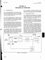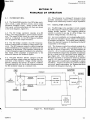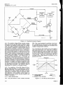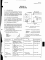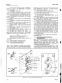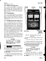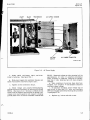
1
HP Archive
This vintage Hewlett Packard document was preserved
and distributed by
www. hparchive.com
Please visit us on the web !
Thanks to on-line curator: Kenneth Kuhn for supplying and
scanning this vintage document.
OPERATING AND SERVICE MANUAL
MODEL 2 0 4 B
SERIALS P R E F I X E D : 416-
OSCILLATOR
Copyright
01369-4
HEWLETT-PACKARD COMPANY
I962
P r i n t e d : JUNE 1964
Model 204B
Index
SECTION I
GENERAL I N F O R M A T I O N
SECTION II
INSTALLATION
S E C T I O N 111
SECTION IV
PRINCIPLES O F O P E R A T I O N
SECTION V
SECTION VI
I
01369-1
OPERATION
MAINTENANCE
REPLACEABLE P A R T S
iii
Table of Contents
List of Illustrations
List of Tables
Model 204B
T A B L E OF C O N T E N T S
Section
Page
I
GENERAL INFORMATION
1-1
1-1 . Introduction . . . . . . . . . . . 1-1
1-4. Power Supply
1-1
1-6 . Mercury and Rechargeable Batteries 1-1
1-8 Accessories Available
1-1
1-10. Instrument Identification . . . . . 1-1
. . . . . . . .
. . . . . . . . . .
. . . . . .
.
I1
111
INSTALLATION . . . . . . . . .
2-1 . Inspection . . . . . . . . .
2-4
Rack / Bench Instructions
2-6 .
Combining Case . . . . .
2-8 .
Adapter F r a m e . . . . .
2-10 Battery-Powered Oscillators
2-12 . AC-Powered Oscillators
2-16 Repackaging for Shipment . .
. . . 2-1
. . . 2-1
.
. . . . . 2-1
. . . 2-1
. . . 2-1
.
. . . 2-1
. . . . . 2-1
.
. . . 2-2
OPERATION . . . . . . . . . . . . . . 3-1
3-1 . Introduction . . . . . . . . . . . 3-1
3-3 .
3-5
3-10
.
............
.
3 -16 .
3-20 .
3-26 .
I
Procedure
General Operating Considerations
Operation With Rechargeable
Batteries
Recharging Nickel-Cadmium
Batteries
Cycle-Life of Nickel-Cadmium
Batteries
Mercury Battery Replacement . .
.
...........
..........
..........
IV PRINCIPLES OF OPERATION
4-1 . Introduction . . . . .
4-7 . Oscillator Circuit
4-13 . P e a k Detector . . . .
V
3-1
3-1
3-1
3-2
3-2
3-2
.
. . . . . .
4-1
. . . . . . 4-1
. . . . . . . . 4-1
. . . . . . 4-2
MAINTENANCE . . . . . . . . . . . . 5-1
5-1 . Introduction . . . . . . . . . . . 5-1
5-3 . Required Test Equipment . . . . . 5-1
Section V (Cont'd)
Page
5.5 . Performance Checks . . . . . . . 5-1
5.7 .
Dial Accuracy Check . . . . . 5-1
5-8.
Frequency Response and
Output Voltage Check . . . . . 5-2
5-9 .
Distortion Check
5-2
5-10 . Repair . . . . . . . . . . . . . 5-3
5-12
Cover Removal . . . . . . . . 5-3
5-14 .
Servicing Etched Circuit Boards . 5-3
5 -16 . Troubleshooting . . . . . . . . . 5-4
5-18 . Adjustment and Calibration . . . . 5-4
5-19 .
AC Power Supply Checks
5-4
5-23
Battery Charger Current
Adjustment
5-4
5-26 .
DC Bal Adjustment . . . . . . 5-5
5-28
Distortion Check
5-5
5-29
Frequency Calibration
Adjustments
5-5
5-31 Replacement Procedures
5-6
5-32
Cam Cable Replacement
5-6
5-34
Frequency Potentiometer
Replacement
5-6
5-36 .
Range Switch Assembly
Replacement
5-7
5-38 Battery-Pack Power Supply
5-8
5-40 AC Power Supply
5-8
5-42 Rechargeable Battery Power
Supply
5-8
5-45
Replacement of Rechargeable
Batteries
5-8
.......
.
.
.
.
.
.
.
.
.
.
.
....
..........
........
.........
.....
....
.........
.........
....
.........
..............
...........
REPLACEABLEPARTS . .
6-1
Introduction . . . .
6-2
Ordering Information
VI
.
. . . . . .
. . . . . .
......
6-1
6-1
6-1
LIST OF I L L U S T R A T I O N S
Number
Page
1.1
Model 204B Oscillator
1-0
2.1
Combining Case
2-0
Steps to Place Instrument into
2.2
Combining Case
2-0
2.3
Adapter F r a m e Instrument Combinations 2-1
2.4
TwoSubmodule Units inRack Adapter
2-2
3.1
Front Panel Controls, Connectors
and Operating Instructions
3-0
3.2
Rear View of Model 204B Showing
Mercury Batteries Installed
3-2
4.1
Block Diagram
4-1
4.2
Simplified Schematic Diagram
4-2
4.3 . RC Network Characteristics
4-2
Test Setup for Dial Accuracy o r
5.1
Distortion Checks
5-1
Test Setup for Frequency Response
5.2
and Output Voltage Check
5-2
.
.
.
.
.
.
.
.
.
.
.
..........
.............
............
...
......
......
..............
......
.......
...........
.......
Number
5.3
Cover Removal
5.4
Model 204B. Exploded View
5.5
Cams and Cable Relationship
5.6
Range SwitchDetail
Rear View of Battery-Powered
5.7
Model 204B
5.8
AC Power Supply Installation
5.9
Rear Internal View of Rechargeable
Battery Power Supply
5.10
Oscillator and Amplifier with Battery
Pack Power Supply
.
.
.
.
.
Page
5-3
5-4
5-6
5-7
..............
.......
.......
............
. . . . . . . . . . . . . . . 5-8
. . . . . . . 5-9
.
.
.
. . . . . . . . . . 5-10
. . . . . . . . . . . 5-11
5.11
. Option 02 Power Supply with
5.12
.
Rechargeable Batteries
. . . . . . . . . 5-12
. . . . . . . . 5-13
Option 01 AC Power Supply
LIST OF TABLES
1
Number
1.1. Specifications . . . . .
5.1 . Required Test Equipment
5.2
Dial Accuracy
.
01369-3
. . . . . . .
. . . . . . .
Page
1-1
5-1
5-2
. . . . . . . . . . . .
Number
5.3
Troubleshooting Summary . .
6-1
Index by Reference Designator
6.2
Replaceable Parts . . . . . .
.
.
.
. . . .
. . . .
. . . .
Page
5-5
6-2
6-5
V
Section I
Paragraphs 1-1 t o 1-11
Model 204B
SECTION I
GENERAL I N F O R M A T I O N
1-1.
INTRODUCTION.
1-2. The Model 204B Oscillator (figure 1-1) is a
transistorized battery-powered instrument which produces sine-wave signals in the 5-cps t o 560-kc range.
The output is 10 milliwatts into 600 ohms and is continuously adjustable over at least a 40-db range. Into
the rated load of 600 ohms, frequency response is
within &3%. The oscillator output is floating, isolated
from power line ground and instrument chassis.
1-3. The 600-ohm output impedance of the oscillator
makes it compatible with transmission lines and many
distribution systems. When battery-powered, the
oscillator is useful for isolated applications. The @
Model 403A/B AC Voltmeter, a l s o battery-powered,
makes an ideal companion instrument f o r the Model
204B.
developing. The nickel cadmium batteries are sealed butpresent no problem ifproperly used (see Section
111). The following precautions should be followedfor
either type of battery:
a . DO NOT short circuit either type of battery.
b. Dispose of batteries promptly when they have
exhausted or will not operate equipment up t o
specifications.
c. Never dispose of batteries by fire.
d . Turn off battery powered equipment when not
in use.
e. Store batteries in a cool well-ventilated place.
1-8.
1-4.
I'
O P T I O N S AVAILABLE.
POWER SUPPLY.
1-5. Normally the oscillator is equipped with a batt e r y pack which consists of four 6.75-volt mercury
batteries. If operation from AC is desired, an AC
power supply (Option 1) or a power supply with r e chargeable batteries (Option 2) may be used. Both
of these power supplies operate from 115 or 230 volts,
and a r e in kit form for field installation. Thebattery
pack is a l s o in kit form. All t h r e e types of power
supplies mount in the s a m e location in the instrument
and can be easily interchanged in the field.
1 - 6 . MERCURY A N D RECHARGEABLE
BATTERIES.
1-7. Mercury batteries used in the Battery P a c k a r e
vented t o prevent excessive internal p r e s s u r e s from
1-9. The following t h r e e power supplies a r e available in kit form for field installation:
Battery Pack Power Supply - 204B-64B
AC Operated Power Supply - 204B-llA
Rechargeable Battery Power Supply - 204B-11C
1-10. INSTRUMENT I D E N T I F I C A T I O N
1-11. Hewlett-Packard used a two-section, eightdigit s e r i a l number (000-00000). If the first t h r e e
digits of the serial number on your instrument do not
a g r e e with those on the title page of this manual,
change sheets supplied with the manual will define
differences between your instrument and the Model
204B described in this manual.
Table 1-1. SI x i f icat ions
FREQUENCY RANGE: 5 cps t o 560 kc in 5 ranges,
vernier control
DISTORTION: L e s s than 1%
DIAL ACCURACY: *3%
POWER SOURCE: 4 batteries at 6 . 7 5 volts each,
7-ma drain, life at least 300 hours.
FREQUENCY RESPONSE: *3%, with rated load
DIMENSIONS: Module 6-3/32 in. high, 5-1/8 in.
wide, 8 in. deep
NET WEIGHT: 6 lb
OUTPUT IMPEDANCE: 600 ohms
OUTPUT: 10 milliwatts ( 2 . 5 vrms) into 600 ohms,
5 v r m s open circuit, completely floating
OUTPUT CONTROL: Continuously variable bridged
"TtTattenuator with at least 40-db range
01369-4
NOISE: Less than 0.05%, a c or battery operated
EQUIPMENT AVAILABLE: 204B-llA, AC Supply
Kit for field installation, 204B-llC Rechargeable Battery Supply Kit for field installation,
204B-64B, Battery Kit for field installation.
1-1
W
Section I1
Paragraphs 2 - 1 to 2-14
Model 204B
S E C T I O N II
INSTALLATION
2 -1.
INSPECTION.
2-2. Unpack the instrument upon receipt and inspect
it for signs of physical damage such as scratched
surfaces, broken knobs, etc. If damage is apparent,
proceed as described in the "Claim for Damage in
Shipment" section of the warranty in the r e a r of this
manual,
2-3. An electrical inspection should be performed
as soon as possible after receipt; s e e paragraph 5-5
for performance checks. These a r e good test procedures for incoming quality-control inspection.
2- 4.
RACK/ BENCH INSTRUCTlONS.
2-5. The Model 204B is shipped with plastic feet and
a tilt stand attached, ready for u s e as a bench-type
instrument. To adapt the Model 204Bfor rackmounting, remove the plastic feet identifiedin figure 5-3 by
following the procedure given in paragraph 5-13 (c)
.
2-6.
COMBINING CASE.
2-7. The combining case shown in figure 2-1 is a
full-module unit which accepts varying combinations
of submodule units such as the Model 204B. Being a
full-module unit, the combining case can be used as
a bench model or it can be rack mounted. Instructions
for use of the combining case a r e given graphically in
figure 2-2 for 1/2-module units. The Model 204B is
a 1/3-module unit, therefore it is necessary to use
either the right o r left divider latch when installing
the divider assembly.
2-10.
BATTERY-POWERED OSCILLATORS.
2-11, Power for battery-powered oscillators is supplied from four 6.75-volt Mallory mercury batteries.
T h e r e a r e no special installation instructions for
placing battery -powered oscillators into operation.
T o convert for operation from an a c power supply or
a rechargeable battery power supply, refer t o paragraph 5-35.
2-12.
AC-POWERED OSCILLATORS.
2-13. POWER REQUIREMENTS. When the Model
204B has an a c power supply or the rechargeable
battery power supply, a source of 115 or 230 volts
+lo%, 50 to 1000 cps will be required. When the
source is 115 volts, set the switch, located on the
r e a r panel, so that the number 115 appears. If a
230-volt source is used, place the switch s o that the
number 230 appears.
2-14. POWER CABLE. For the protection of operating personnel, the National Electrical Manufacturers'
Association (NEMA) recommends that the instrument
panel and cabinet b e grounded when being operated
from an a c power line. Instruments with the acpower
supply or rechargeable battery power supply a r e
equipped with a detachable, three-conductor power
cable which, when plugged into an appropriate receptacle, grounds the instrument. The offset pin on the
power cable three-prong connector is the ground pin.
FILLER PANEL
2-8. ADAPTER FRAME.
2-9. The adapter frame is simply a rack frame that
accepts any combination of submodule units (see figu r e 2-3); it can only b e rack mounted. Instructions
a r e as follows:
a. Place adapter f r a m e vertically on edge of bench
as shown in step 1 , figure 2-4.
b. Stacksubmoduleunits i n f r a m e as shown in step
2 , Place spacer clamp between units, step 3
c. P l a c e two end spacer clamps as shown in step
4 , and push submodule units into frame.
d. Insert screws on either side of frame, step 5 ,
and tighten until submodule units a r e tight in
frame.
e . The complete assembly is now ready for rack
mounting.
01369-3
Figure 2-3. Adapter Frame Instrument
Combinations
2-1
Section I1
Paragraphs 2-15 t o 2-17
Model 204B
2-15. To preserve the protectionfeature when operating the instrument from a two-contact outlet, use a
three-prong t o two-prong adapter and connect the
pigtail on the adapter t o ground.
2-16.
REPACKING FOR SHIPMENT.
2-17. The following is a general guide for repackaging an instrument for shipment. If you have any
questions, contact your local @sales office or repair
facility. Proceed as follows:
a. Place instrument in original container if avaiable. If original container is not available, it can be
purchased from your nearest Hewlett-Packard Sales
and Service Office (refer to maps in Appendix).
ADAPTER
FRAME
T
1/2 MODULE
INSTRUMENT
b. If original container is not used, wrap instrument in heavy paper o r plastic before placing in
inner container.
CLAMP
c. Use a heavy carton o r wooden box to house the
instrument and inner container and use strong tape o r
metal bands to seal the shipping container.
d. Mark shipping container with "Delicate Instrument", "Fragile", etc. as appropriate.
Note
If instrument is to be shippedto HewlettPackard for service o r repair, attach a tag
to instrument identifying owner,model
number, s e r i a l number, and indicating
service o r repair to be performed. In any
correspondence identify instrument by
model number and s e r i a l number,and
s e r i a l number prefix.
2-2
204B-M-10A
Figure 2 -4. Two Submodule Units
in Rack Adapter
01369-3
Section 111
Figure 3-1
Model 204B
Operation
Controls and Connectors
1. For selecting frequency range. I nO F F position
oscillator is inoperative.
2. On indicator; glows in all positions of RANGE
switch except OFF.
3 . For selecting frequency within desired range.
Dial calibration multiplied by RANGE switch
position gives output frequency in cycles per
second.
a. Connect load t o OUTPUT 60052(6)terminals.
b . Select frequency with RANGE (1)and FREQ.
(3). Example: If FREQ. i s set to 20 and
RANGE t o XlK, the oscillator's output frequency is 20 kc (20 cps x 1K = 20 kc).
c. Set AMPLITUDE (5) for desired power level.
Not e
4. Provides fine frequency adjustment. Dial is
calibrated with arrow in vertical position.
5 . For selecting desired output level (10 mw maximum into 600 ohms).
6. Output terminals, floating; impedance, 600
7.
If oscillator is equipped with AC P a v e r Supply or Rechargeable Battery Power Supply,
turning RANGE switch t o O F F does not turn
AC Power Supply or Battery Charger off.
Disconnect power cord t o turn either of these
two power supplies off,
cabinet ground terminal.
Figure 3-1. Front Panel Controls, Connectors, and
Operating Instructions
3 -0
01369-3
Section I11
Paragraphs 3-1 to 3-15
Model 204B
S E C T I O N 111
OPERATION
INTRODUCTION 0
3-2. The Model 204B has four operating controls and
one output connector (see figure 3-1). A sinewave
signal in the 5-cps to 560-kc range is selected by
positioning the FREQ. , RANGE, and VERNIER controls. Output power level is controlled by the
AMPLITUDE control which has a t least a 40-db range.
A 115/230 volt switch is on the rear panel when oscillators are equipped with an a c power supply o r rechargeable battery power supply,
3 - 3 . PROCEDURE.
3-4. Operating instructions for the Model 204B are
given in figure 3-1.
3 - 5 . GENERAL OPERATING
CONSIDERATIONS.
3-6. T o prevent damage to transistors i n the oscillator, a blocking capacitor should be used in s e r i e s
with the output when connecting to a load a c r o s s which
there is a dc potential difference. When the capacitor
is used, initial current surge must be limited to a
capacitance-voltage product less than 200 microfaradvolts. F o r example, if a 20-volt potential difference
exists a c r o s s the load. use a 10-uf capacitor (10uf x
20 v = 200 !.
fv).
l
CAUTION
DO NOT CONNECT THE OSCILLATOR
ACROSS LOADS WHICH ARE REFERENCED
O F F GROUND
BY MORE THAN rt25
VOLTS; HIGHERVOLTAGES WILL BREAK
DOWN COMPONENT INSULATION,
3-7. When the Model 204B is initially turned on and
RANGE switch is s e t to X1, allow 20 seconds for oscillator to stabilize; only a few seconds are necessary
for stabilization when switching to other RANGE positions.If FREQ. dial is sweptat too fast a rate, output voltage fluctuations will occur (since a wirewound
resistor is used as the variable frequency determining
element). If sweep speed is decreased o r sweeping is
stopped, oscillator output will stabilize at its normal
level.
3-1.
3-8. To obtain maximum amplitude stability from
battery-powered oscillators, wait 20 minutes after
turn-on to permit the battery voltage to stabilize. This
effect may cause as much as a 1% change in amplitude
during the first 20 minutes of operation.
3-9. When operating from batteries (Mercury o r
Nickel-Cadmium) the batteries require replacement o r
recharging (Nickel-Cadmium batteries only) when
maximum oscillator output becomes less than 5.0 volts
rms open circuit o r less than 2.5 volts r m s into 600
ohms. For mercury battery replacement data, refer
to paragraph 3-26. Charging instructions for nickelcadmium batteries are given in paragraph 3-16.
3 - 1 0 . OPERATION W I T H RECHARGEABLE
BATTERIES.
3-11. There is no change in the operating procedure
for an instrument in which the rechargeable battery
01369-4
supply has been installed. However, this power supplypermits either a c operation for 115/230 vac &lo%
(selected by switch on r e a r ) 50 to 1000 cps power
sources o r battery operation for portable applications.
Battery operation only (with charger power cord discotnected) is required a t temperatures below 32'F
(0 $!) and is recommended at temperatures above
104 F (4OOC).
3-12. When the RANGE switch is turned OFF,power
is removed from the oscillator portion of the instrument and a resistor is connected a c r o s s the output of
the
power
supply. The charger will continue to
operate as long as the power cord is connected to a
power source. The resistor, placed a c r o s s the output of the power supply, acts as a load in place of the
oscillator section to maintain a constant charge rate
through the batteries. A diode in the output circuit
prevents battery discharge when the oscillator is not
connected to a power source.
3-13. It is recommended that the power cordbe connected to a power source whenever possible. This
w i l l prevent self-discharge of the battery cells and will
a s s u r e a fully charged battery whenever portable
operation is required. Turn the oscillator OFF when
not in use, particularlywhen operating with the power
cord disconnected.
3-14. When fully charged, the batteries will power
the oscillator for approximately 40 hours of continuous o r intermittent operation provided they a r e at a
temperature of 81 F + l o If the batteries a r e operated at higher o r lower temperatures their capacity
is reduced as the temperature extremes are approached; approximately28 h o p at 122 F (500C) o r approximately 20 hours at -4 F (-20 C). At temperatures
beyond these extremes the batteries a r e not capable
of supplying their characteristic stable discharge
voltage.
.
3-15. The +122'F to -4'F temperature range is
adequate for most users, however, keep these limits
in mind when operating under field cotditions. Internal temperatures in excess of 122 F are easily
obtained if the instrument is left in the sun, even with
a moderate ambient temperature. Good practice would
be to avoid storing, transporting, o r operating in
direct sunlight other than for a very short period. Also
avoid placing the instrument in a location where
surrounding equipment might excessively raise the
internal temperature.
CAUTION
THE HERMETICALLY SEALED CELLS IN
THESE BATTERIES MAY BE PERMANENTLY
DAMAGED OR THEIR LIFE DRASTICALLY
REDUCED I F EXPOSED TO EXTREMELY HIGH
TEMPERATURES. THIS DANGER INCREASES
UNDER PROLONGED CONDITIONS.
3-1
Model 204B
Section I11
Paragraphs 3-16 to 3-27
3- 16, RECHARGING NICKEL- CADMIUM
BATTERIES.
3-17. The batteries should be considered as fully
discharged when maximum oscillator output drops
below 5.0 volts r m s opencircuit o r l e s s than 2. 5 volts
r m s into 600 ohms. The batteries w i l l not operate
much longer when this point is reached and the oscillator probably will not meet specifications. Excessive discharge of batteries may damage them o r
shorten their life.
3-18. To recharge batteries, turn oscillator O F F and
connect power cord to a suitable power source. The
batteries will be fully charged in approximately 60
hours a t a 5 . 5 miliiampere charge current and 30
hours a t a 11 milliampere charge current if they were
fully discharged at the beginning. The instrument can
be turned on for use after an initial charge of at least
20 minutes. If the batteries were only partiallydischarged, the oscillator can be turned on for use at any
time. The charge rate is the same whether the oscillator is O F F o r operating; therefore, very little increase in charging time will be required i f the instrument is used while the batteries a r e being recharged
The charge circuit can be increased with the charge
current adjustment R102 ( r e f e r to figure 5-11) to a
maximum of 11 milliamperes to provide a quick
charge. The 11 milliampere charge rate should be
used for quick charge only. Repeated chargingat a
high rate w i l l shorten battery life.
3-19. The batterJes can beocharged at ang temperature between +32 F to +122 F (0 C to +50 C). However, to obtain optimum battery life,
recharging
should be tone at a temperature of 80.6'F *lO°F
(27OC *5.6 C).
CAUTION
THE FOUR NICKEL-CADMIUM BATTERIES
ARE HERMETICALLY SEALED AND CAN BE
DAMAGED I F CHARGED AT A FAST RATE
AT A TEMPERATURE EXCEEDING 1 2 2 F
(5OOC). I F THE CHARGE CURRENT ADJUSTMENT HAS BEEN SET FORA QUICK CHARGE
RATE, PLACE THE INSTRUMENT I N
A
LOCATION WHERE THE
AMBIEYT
TEMPERATURE DOES NOT EXCEED 104 F
(4OOC).
3-20.
p e r e s with discharge c a r r i e d to the normal ten-hour
end voltage (1.10 volts/cell x 5 = 5.50 volts/battery)
on every cycle. Under these conditions a cycle-life
in excess of 100 cycles can be expected.
3-24. When used topowerthe @ Model 204BOscillator, the batteries a r e discharged a t approximately a
40 hour rate. The batteries a r e not fully discharged
if they are recharged as recommended in paragraph
3-16.
3-25. Optimum battery life can be obtained by following a simple routine of 1) preventing complete
battery discharge by recharging before the oscillator
output level drops below 5.0 V r m s into an open circuit (2. 5 V r m s into 600 ohms), 2) keeping the use of
a quick charge to a minimum, 3) operati.i,r a t moderate temperatures whenever possible and 4) by disconnecting power cord after 60 hours of continuous
charging with oscillator turned O F F (30 hours if
charging batteries a t a quick charge rate).
3-26.
MERCURY BATTERY REPLACEMENT.
3-27. Battery replacement is required wnen the
oscillator output becomes l e s s than 5.0 volts r m s open
circuit o r l e s s than 2. 5volts r m s into 600 ohms provided the DC BAL is adjusted correctly. Replace the
batteries with four 6. 75-volt mercury batteries
(Mallory type TR235R o r equivalent). Refer to figure
3-2, and proceed as follows:
a. Remove top cover retaining screw and slide
cover from instrument.
b. Remove wing nuts and battery clamps.
c. Remove and dispose of batteries according to
paragraph 1-6.
d. Install replacement batteries s o that battery
polarity matches polarity designation on battery
clamps.
e. Replace battery clamps and wing nuts.
f . Replace top cover.
POLARITY
DES IGN-ATION
WING
NU T
CYCLE-LIFE O F NICKEL-CADMIUM
BATTERIES,
3-21. As extremes in temperatures a r e approached,
the cycle-life (complete charge-discharge cycles) of
the batteries is reduced. Storage a t high temperatures w i l l increase the self-discharge rate and also
decrease the cycle-life. Permanent battery damage
may result if the batteries a r e stored at a high temperature for a prolonged period.
3-22. Battery cycle-life canbe extended by recharging before the batteries a r e completely discharged,
charging and discharging at a rate which is slower
than the maximum ten-hour rate specified by the
manufacturer, and by not overcharging.
3-23. The cycle-life of the batteries i s based, by
the manufacturerer,on an endpoint of 80% of the rated
225 milliampere-hour capacity. This is with a tenhour charge and discharge current of 22. 5 milliam3-2
I
2046-S-I
BATTERY
CLAMP
Figure 3-2. Rear View of Model 204B Showing
Mercury Batteries Installed.
01369-2
Model 204B
Section
Paragraphs 4 - 1 to 4-10
SECTION
P R I N C I P L E S OF O P E R A T I O N
4-1.
INTRODUCTION.
4-2. The Model 204B consists of an RC bridge oscillator circuit, a peak detector circuit, and an output
attenuator (bridged-T type). These circuits and the
front panel controls associated with them a r e shown
in the block diagram, figure 4-1.
4-3. The RC bridge oscillator consists of an RC
bridge, atwo-stage amplifier, and two emitter followers. The output of t h i s circuit is a sine-wave signal
which is 1) returned t o the RC bridge a s feedback,
and 2) applied t o the output attenuator.
4-4. The RC bridge consists of an RC frequencyselective networkand a resistive voltage divider net work. The RC frequency-selective network supplies
positive feedback t o the amplifier and determines the
frequency of oscillation. The resistive voltage divide r network suppliesnegativefeedbacktothe amplifier.
The output of the amplifier is proportional t o the
difference between the feedback signals.
4-5. The peak detector detects changes in the RC
bridge oscillator output voltage and changes the division ratio of the resistive voltage divider network,
thereby changing the amount of negative feedback.
The peak detector with the divider networkmaintains
the RC oscillator output at a constant level.
4-6. The attenuator is a bridged-T attenuator which
provides continuous control of the oscillator output
voltage while maintaining constant output impedance.
4-7.
OSCILLATOR CIRCUIT.
4-8, The RC bridge in the oscillator circuit consists
of an RC frequency-selective networkand a resistive
voltage divider network. The frequency-selective
network is similar t o one leg of a Wien bridge; the
resistive voltage divider, the other leg.
4-9. A s in any oscillator, an in-phase feedbackvoltage (from the oscillator circuit output) is necessary
t o maintain oscillations. The proper phase relationship at the desired frequency is maintained by theRC
components in the bridge.
4-10. The frequency-selective network consists of a
series branch, C1 and R1, and a parallel branch, C2
and R2, as shown in figure4-2. For the frequency at
which X = R in the s e r i e s andparallel branches, the
positive feedback voltage t o the amplifier is maximum
and is in phase with the oscillator circuit output voltage (figure 4-3). Only that frequency at which X =
Rwill be amplified; at frequencies where Xcdoes fiot
equal R, the positive feedback voltage is not of the
right phase and is insufficient in amplitude t o sustain
oscillation. Figure 4-3 shows the positive feedback
curve and phase relationship for frequencies above
and below the frequency where X = R.
C
\
I
RC
BRIDGE
(RIOA,B,C2,C7)
FEEDBACK
AMPLIFIERS
ATTENUATOR
EMITTER
FOLLOWERS
,
!
,
PEAK
DETECTOR
Q5 ,CR6
Figure 4-1, Block Diagram
01369-2
4-1
20
Section
P a r a g r a p h s 4-1 t o 4-10
SECTION IV
P R I N C I P L E S OF O P E R A T I O N
4-1.
4-6. T h e attenuator is a bridged-T attenuator which
provides continuous control of t h e oscillator output
voltage while maintaining constant output impedance.
INTRODUCTION.
4-2. T h e Model 204B c o n s i s t s of a n RC b r i d g e o s c i l lator c i r c u i t , a peak d e t e c t o r c i r c u i t , and a n output
attenuator (bridged-T type). T h e s e c i r c u i t s and t h e
front panel c o n t r o l s a s s o c i a t e d with t h e m are shown
in the block d i a g r a m , f i g u r e 4-1.
4-7.
4-8. T h e RC b r i d g e in t h e o s c i l l a t o r circuit c o n s i s t s
of a n RC frequency-selective networkand a r e s i s t i v e
voltage divider network. T h e frequency-selective
network is s i m i l a r t o one l e g of a Wien b r i d g e ; t h e
r e s i s t i v e voltage d i v i d e r , t h e other leg.
4-3. T h e RC b r i d g e o s c i l l a t o r c o n s i s t s of a n RC
b r i d g e , a t w o - s t a g e a m p l i f i e r , and two e m i t t e r follow e r s . T h e output of t h i s c i r c u i t is a sine-wave signal
which is 1) r e t u r n e d t o t h e RC b r i d g e as feedback,
and 2) applied t o t h e output a t t e n u a t o r .
4-9. A s in any o s c i l l a t o r , an in-phase feedback volta g e (from t h e o s c i l l a t o r circuit output) is n e c e s s a r y
t o maintain oscillations. T h e p r o p e r p h a s e r e l a t i o n ship at t h e d e s i r e d frequency is maintained b y t h e R C
components in t h e b r i d g e .
4-4. T h e RC b r i d g e c o n s i s t s of a n RC frequencys e l e c t i v e networkand a r e s i s t i v e voltage divider net work. T h e RC frequency-selective network supplies
positive feedback t o t h e a m p l i f i e r and d e t e r m i n e s t h e
frequency of oscillation. T h e r e s i s t i v e voltage divide r network s u p p l i e s negative feedback t o t h e a m p l i f i e r .
T h e output of t h e a m p l i f i e r is proportional t o t h e
difference between t h e feedback s i g n a l s .
4-10. T h e frequency-selective network c o n s i s t s of a
s e r i e s branch, C1 and R1, and a p a r a l l e l b r a n c h , C2
and R2, as shown in f i g u r e 4 - 2 . For t h e frequency at
which X = R in t h e s e r i e s a n d p a r a l l e l b r a n c h e s , t h e
positive f e e d b a c k voltage t o t h e amplifier is maximum
and is in p h a s e with the oscillator circuit output volt a g e (figure 4-3). Only that frequency at which X =
R w i l l b e amplified; at frequencies w h e r e Xc does got
equal R, t h e positive feedback voltage is not of t h e
right p h a s e and is insufficient in amplitude t o sustain
oscillation. Figure 4-3 shows t h e positive feedback
c u r v e and p h a s e relationship f o r f r e q u e n c i e s above
and below t h e frequency w h e r e X = R.
4-5. T h e peak d e t e c t o r d e t e c t s changes in t h e RC
b r i d g e o s c i l l a t o r output voltage and changes t h e divis i o n r a t i o of t h e r e s i s t i v e voltage divider network,
t h e r e b y changing t h e amount of negative feedback.
T h e peak d e t e c t o r with t h e divider n e t w o r k m a i n t a i n s
t h e RC o s c i l l a t o r output at a constant level.
\
RC
BRIDGE
(RIOA,B,C2,C71
,
FEEDBACK
OSCILLATOR C I R C U I T .
C
\
AMPLIFIERS
Q I , Q2
EMITTER
FOLLOWERS
0 3 , 04
--
ATTENUATOR
I
I
R40A,Bh
I
I
I
I
FEEDBACK
F i g u r e 4-1.
01369-2
Block Diagram
4-1
Section IV
Paragraphs 4-11 to 4-15
Model 204B
Figure 4-2.
Simplified Schematic Diagram
4-11. The resistive voltage divider network consists
of R3 and Z1 which provide negative feedback voltage
t o maintain the oscillator circuit output at a constant
level. The negative feedback is developed in part due
t o the dynamic resistance of CR4 and CR5 which is
controlled by the amount of forward bias applied t o
the diodes by the peak detector circuit. If the oscillator circuit output changes, the peak detector detects
the change and converts it to a new bias level for the
diodes. Diode conduction changes (seen as an impedance change in the bridge), and results in a differing
amount of negative feedback, If the negative peak of
the oscillator output signal exceeds -7 volts then, the
peak detector circuit would decrease the forward bias
on CR4 andCR5, increasing diode dynamic resistance.
Increased impedance in Z1 of the divider increases
the amount of negative feedback t o the emitter of the
amplifier. Increasing the negative feedback results
in a decrease in the net input tothe amplifier and thus
the output signal decreases. The oscillator output is
maintained at a constant 14 volts peak-to-peak.
4-12. Two amplifiers, Q1 and Q2, (figure 5-9) a m plify the signal and apply it to complementary emitter
followers Q3 and Q4. The emitter followers a r e f o r ward biased by CR2 and CR3 and under a no-signal
condition a r e conducting slightly t o minimize crossover distortion. The oscillator circuit output is
sampled by the peak detector and also coupled t o the
bridged-T attenuator.
4-13.
P E A K DETECTOR.
4-14. The peak detector circuit consists of Q5 and
4-2
CR6. This circuit samples the oscillator circuit output, and supplies bias proportional t o the output signal
t o control the dynamic resistance of the diodes in the
resistive voltage divider network.
4-15. Peak detector Q5 conducts only on the negative
peak of the output signal. At 7 volts peak, breakdown
diodeCR6 breaks down and t h e voltage at the junction
of CR6 and C25 through C29 decreases. This changes
the bias t o CR4 and CR5, which affects the resistance
of these diodes. Capacitors C25 through C29 act to
averagethe bias voltage applied t o t h e diodes over the
period of one cycle.
FREQUENCY
LAG
0A
0.3
PHASE
F
0.2
0
LEAD
R
POSITIVE FEEDBACK
TO AMPLIFIER
FEEDBACK TO RC NETWORK
Figure 4-3.
RATIO
PHASE
-
204 0 - S - 1 3 A
RC Network Characteristics
01369-2
Model 204B
Section V
Paragraphs 5-1 t o 5-7
SECTION V
MAINTENANCE
5-1.
INTR
U
I
N.
5-2. This section provides maintenance and service
information for the Model 204B Oscillator. Required
test equipment, replacement and adjustment procedures, and a troubleshooting summary are included
in the section. Also includedare performance checks
which verify proper instrument operation,
5-3.
FOR DIAL ACCURACY
@ 2040
I
I
I
I
I
REQUIRED TEST EQUIPMENT.
5-4. Test equipment required for maintaining and
checking performance of the Model 204B is listed in
table 5-1. Equipment having similar characteristics
can be substituted for the equipment listed.
5-5.
5232A/ S 3 2 A
0 3 3 0 C/D
-6OOn
P E R F O R M A N C E CHECKS.
5-6. The performance checks verify that the Model
204B is operating normally and is accurately calibrated. These checks may be used after maintenance
or as part of incoming quality control inspection. In
the following checks be s u r e the test equipment used
has been recently calibrated.
5-7. DIAL ACCURACY CHECK.
c . Set frequency counter controls as follows:
a. Connect frequency counter and 600-ohm load t o
oscillator output as shown in figure 5-1.
b. Set Model 204B controls as follows:
.............
............
RANGE.,
FREQ.. . . .
AMPLITUDE.
VERNIER . .
.........
........
Figure 5-1. Test Setup f o r Dial Accuracy
or Distortion Checks
XI
5
MAX.
centered
Function. ,
100 PERIODS AVERAGED
SENSITIVITY, . . . . . . . . . . . .
3
DISPLAY.
maximum counterclockwise
d. Counter should read 200 i 6 milliseconds.
e. Set FREQ. dial t o 20, counter should read 50.0
i 1 . 5 milliseconds.
Table 5-1. Required Test Equipment
Instrument Type
Oscilloscope
Distortion Analyzer
AC Voltmeter
DC Voltmeter
Clip-On
Milliammeter
Frequency Counter
01369-3
Required Characteristics
Us e
Recommended Model
Passband: d c t o 600 k c
Sensitivity: 0 . 1 volts/cm
Input Impedance: 1 megohm
Measure distortion to -40 db
1 kc
Frequency Range: 5 cps to
600 kc
Voltage Range: 1 mv to 5 volts
Accuracy: *l%
Voltage Range: Positive and
negative voltages from 100 m
to 15 volts
Input impedance: a t least 10
megohms
Range: 5 to 11 milliamperes
Accuracy: *3%
Waveform checking
@ Model 175A with
plug-in Model 1753A
Distortion measurement
@ Model 330B/C/D
AC voltage measurements
@I, Model 400H
DC voltage measurements
@ Model 412A
Charge current
measurements
@ Model 428A
Counting Range: 5 cps to 600 kc
Accuracy: 0.03%
Frequency measurements
@ Model 5232A/5532A
5-1
Section V
Paragraphs 5-8 t o 5-9
Model 204B
f . Set FREQ. dial t o 50, counter should read 20.0
*O. 6 milliseconds.
g. Set RANGE t o XlOand FREQ. dial t o 5, counter
should read the same as step f .
@400H
h. Repeat steps e and f withRANGE atX10. Counter should read 5.00 *O. 15 milliseconds and 2.00
0 2040
f0.06 milliseconds respectively.
i. Set frequency counter function switch t o FREQUENCY (. 1).
j . Complete check by setting RANGE switch and
FREQ. dial as shown in table 5-2, columns one and
two. The counter reading should be as shown in
column three
.
Table 5-2.
Range
Switch
Dial Accuracy
Freq.
Dial
2040 - S -SA
XlOO
XlOO
XlOO
5
20
50
500 cps k 15 cps
2000 cps i 60 cps
5000 cps f 150 cps
X1K
X1K
X1K
5
20
50
5 kc i 150 cps
20 kc i 600 cps
50 kc f 1 . 5 kc
X1OK
X1OK
X1OK
5
20
50
Figure 5-2. Test Setup for Frequency Response
and Output Voltage Check
5-9.
5-8.
50 kc f 1 . 5 kc
200 kc i 6 kc
500 kc f 15 kc
FREQUENCY RESPONSE AND OUTPUT
VOLTAGE CHECK.
a. Connect ac voltmeter and 600-ohm load t o oscillator output as shown in figure 5-2.
b. Set Model 204B RANGE t o X1 and FREQ. dial
t o 25.
DISTORTION CHECK.
a. Connect distortion analyzer and 600-ohm load
t o oscillator output as shown in figure 5-1.
b. Set Model 204B controls as follows:
RANGE. . . .
FREQ.. . . .
AMPLITUDE.
..........
........
.........
XI00
10 (1 kc)
MAX.
c. Set distortion analyzer controls as follows:
. . . . . XlOO
. . . . AF
SET LEVEL
. . . . . . . . . 100%
FREQUENCY RANGE.
INPUT.. . . . . . . . . .
FUNCTION. . . . . . . .
METER RANGE
d. On distortion analyzer:
c. Adjust AMPLITUDE for 2.5 volt reading on
voltmeter.
(1)Adjust INPUT SENSITIVITY for full scale
reading (1.0).
d. Sweep FREQ. dial by hand t o read 50. As dial
is swept, voltmeter reading should not vary more
than &O. 075 volts.
(2) Set FUNCTION t o DISTORTION.
e. Set Model 204B RANGE t o X10.
f . Set FREQ. dial t o 5 and repeat step d.
(3) Adjust FINE and COARSE frequency controls
and BALANCE control for dip at fundamental
frequency (1 kc); switch METER RANGE as
necessary t o monitor dip.
(4) Readjust controls untilabsolute dip is located
g . Complete check with RANGE switch set t o each
untested position while repeating step d.
5-2
e. Meter reading should be less than 1 . 0 on the 1%
range.
01369-3
Section V
Paragraphs 5-10 to 5-15
Model 204B
Figure 5-3. Cover Removal
5-10.
REPAIR.
5-11. When repairing the Model 204B, use the exploded view, figure5-4, as an aid t o identifying p a r t s .
e. Remove bottom cover screw and lift tilt stand.
f . Slide bottom cover t o r e a r and lift t o remove.
g. Remove side cover screws and side covers.
5-12. COVER REMOVAL.
5-13. Remove covers prior t o any check or adjustment which requires power t o be applied. Refer t o
figure 5-3, and proceed as follows:
a. Remove top cover screw.
b . Slide top cover t o r e a r , and lift t o remove.
c. Slide r e a r foot assembly toward side while
pushing foot release.
d. Lift foot assembly to remove.
01369-2
h. To replace covers and foot assembly, reverse
the order of steps a through g.
5-14. SERVICING ETCHED CIRCUIT BOARDS.
5-15. The etched circuit boards used in the Model
204B require that the soldering iron tip be applied to
the conductor side of the board when servicing. For
large components, such as potentiometers, rotate the
soldering iron tip from lead to lead while applying
p r e s s u r e to the part to lift it from the board o r use a
soldering tip such as Ungar #855 3/4 in. Cup Tip. In
addition to the above information, the following should
be observed.
5-3
Section V
Paragraphs 5-16 t o 5-24
Model 204B
Figure 5-4. Model 204B, Exploded View
a. Do not apply excessive heat,
b. Apply heat to component lead on conductor side
of board, and remove lead with a straight upward pull
c. Use a toothpick o r wooden splinter to clean
holes.
d. Solder replacement components from the conductor side.
5-21, Ripple voltage in the ac power supply should be
less than 2 mv. To check ripple voltage, it is nece s s a r y to connect a wire from circuit ground (h)
to
5-16. TROUBLESHOOTING.
5-17. To locate trouble in the Model 204B, s t a r t with
a thorough visual inspection. Look for burned-out
o r loose components, loose connections of any other
condition which suggests a source of trouble. If a
visual inspection does not reveal the trouble, use the
block diagram, figure 4-1, and troubleshooting summary, table 5-3, ad aids for isolating the trouble. The
troubleshooting summary lists indication of and action
to be taken for various troubles; the action should be
taken in the order given.
5-18. ADJUSTMENT AND CALIBRATION
PROCEDURES.
5-19. AC POWER SUPPLY CHECKS.
formed, adjust DC BAL control (paragraph 5-26).
.
5-20. The ac power supplyvoltages a r e typically +13
and -13 volts, but may vary from 12 to 13. 5 volts. As
linevoltage isvariedfrom 103.5 to 126. 5 volts, supply
voltages should remain with the 12 to 13. 5 volt limit.
5-4
the junction of RlOA and S1D. Measure ripple voltage
.
as the line voltage is varied from 103.5 to 126. 5 volts
5-22. When trouble occurs, in the ac power supply
check CR15 and CR16 first. If any repair is per5-23.
BATTERY CHARGER CURRENT
ADJUSTMENT.
5-24. The battery charger current is s e t a t the factory
for 5.5 *O. 5 milliamperes to provide maximum battery
life, Charge current adjustment R102 can be set to
provide a quick charge by increasing the charging
current to not more than 11 milliamperes.
5-25. Use the following procedure to s e t charge
current adjust R102 f o r quick charge operation.
a. Remove top cover from oscillator chassis.
b. Connect power cord to a power source.
c. Turn oscillator OFF.
d. Attach current probe of clip-on milliammeter to
one input lead of battery charger circuit. (See figure
5-11.)
e. Set R102 for the desired charge current.
.
01369-3
1
Section V
Paragraphs 5-25 to 5-30
Model 204B
Note
Do not exceed 11 milliamperes. A
charge current exceeding 11 milliamperes will shorten battery life.
tiometer R36. Voltage should be between 90 and 140
mv r m s on a l l ranges. If voltage is high, increase
resistance of R34; if low, decrease resistance.
c. Set Model 204B controls as follows:
Replace top cover.
RANGE
XI00
F R E Q . . . . . . . . . . . . lO(1kc)
VERNIER.
centered
AMPLITUDE.
MAX.
d. Connect distortion analyzer a c r o s s 600-ohm
load on oscillator output terminals.
e. Measure distortion, and adjust R36 for minimum reading. Reading should be less than 1%.
Note
Do not use coaxial cables (use twin lead
only) and disconnect a l l other equipment
from oscillator when making distortion
measurements.
5-29. FREQUENCY CALIBRATION ADJUSTMENTS.
5-26. DC BAL ADJUSTMENT,
5-27. When the DC BAL control R15 (rear panel) is
properly adjusted there shouldbe no dc voltage present
at the oscillator output. If dc voltage is present, proceed as follows:
a. Connect a DC voltmeter to oscillator output.
(With the optional Rechargeable Battery Power Supply,
connect DC voltmeter between floating ground and
the junction of L1 and C102.)
b. Set AMPLITUDE to MAX.
c. Adjust DC BAL on rear of instrument for a zero
volt reading. If necessary, change the value of R18
for proper range of R15. If DC BAL will not adjust to
.zero volts, check power supply for proper voltages.
5-28.
DISTORTION ADJUSTMENT,
.............
.........
.........
5-30. Frequency calibration adjustments should be
performed, only i f necessary, after repairs are made
to frequency sensitive components.
a. Connect a 600-ohm loadacross the oscillator
output terminals.
a. Connect frequency counter and 600-ohm load to
b. Using a n AC voltmeter, measure the gain conoscillator output as shown in figure 5-1.
trol voltage between circuit ground and a r m of potenTable 5-3. Troubleshooting Summary
i
Action
Indication
No output signal; d c voltage at output
greater than k 1 volt (dc voltage
measured at junction of L1 and
C102 on Option 02 Power Supply
with Rechargeable Batteries)
Check power-supply voltages (+13 and -13 volts)
No output signal; proper dc voltage at
output (zero volts)
Check power-supply voltages (+13 and -13 volts)
Check Q3, Q4, CR2, and CR3 f o r correct dc voltages
(refer t o schematic diagram)
Check Q1, Q2, and CR1 for correct dc voltages
(refer t o schematic diagram)
Check Wien bridge components
Check Q1 and Q2 for correct voltages
Check peak detector circuit (Q5, CR4, CR5, and CR6)
Check RANGE switch contacts
No output on one o r m o r e ranges
Check components connected t o Wien bridge position when
RANGE switch is inoperative position. For example:
If inoperative position is X1, check C2A and C7A.
Check components connected t o peak detector circuit when
RANGE switch is in inoperative position.
Check power-supply voltages (+13 and -13 volts)
Output amplitude not correct and/or
distorted
I
Check components in upper and lower legs of Wien bridge
for proper value *percent of tolerance (refer t o table 6-1
for tolerances). For example: When RANGE switch is in
X1 position, check R24, R4, C2A, RlOA, RlOB, R11, andC7A
Check peak detector circuit (Q5, CR4, CR5, and CR6, forproper operation. Refer towaveforms and voltages in schematic diagram. Be s u r e CR6 breaks down at 7 volts peak.
Check for incorrect voltages at Q3, Q4, Q2, and Q1
respectively
If all ranges a r e affected
~~
If all ranges are NOT affected
01369-4
~~
Check components connected t o peak detector circuit in
affected range
5-5
Section V
Paragraphs 5-31 to 5-35
Model 204B
b. Set Model 204B RANGE to X100, VERMER to
center of its range, and AMPLITUDE to maximum
clockwise position,
c. Set FREQ. to 56 (5.6 kc).
d. Lock FREQ. dial shaft with a number 8-32
socket set screw (dial shaft locking screw) whichins e r t s into threaded hole on top of dial shaft housing
e. Loosen potentiometer (pot) shaft locknut, figure 5-5a, and adjust pot by turning pot a r m to obtain
a 5.6-kc output,
f , Tighten pot shaft locknut, and loosen dial shaft
locking screw.
g. Set FREQ. to 5 (500 cps) and tightendial shaft
locking screw.
h. Loosen dial shaft locknut and adjustdial cam
by turning cam to obtain a 500-cps output.
i. Tighten dial shaft locknut and loosen dial shaft
locking screw.
j . Repeat steps c through i untilfrequencies are
within approximately rtl%.
k. Set RANGE to XlOK, FREQ. to 5 (50 kc), and
adjust C8 (figure 5-6) to obtain a 50-kc output.
m. Set FREQ. to 56 (560 kc), and adjust C15
(figure 5-4) to obtain a 560-kc output. If necessary,
change the value of C14 for proper range of C15.
.
Note
Check gain control voltage according to
steps a and b of paragraph 5-28.
n. All frequencies a c r o s s the band should
within *3%.
be
.
5-34. FREQUENCY POTENTIOMETER
REP LAC EM ENT.
5-35. To replace the frequency potentiometer (pot),
RlOA and B, it is necessary to remove the pot cam
F o r easier access to the cams, remove the screws
holding the power supply and circuit board,
then
swing the two assemblies to the side. Use figure 5-5
as a guide, and proceed as follows:
a. Position cams as shown in figure 5-5a. Some
instruments have aluminum cams which have the
counterweight shown in figure 5-5. Other instruments
.
5 - 3 1 . REPLACEMENT PROCEDURES.
5-32. CAM CABLE REPLACEMENT.
5-33. If it is necessary to replace the cam cable,
order it by @ Stock No. 8160-0003 and description.
F o r easier access to the cams, remove the screws
TERMINAL
holding the power supply and circuit board, then swing
the two assemblies to the side. Use figure 5-5 a s a
guide, and proceed as follows:
a. Orient cams as shown in figure 5-5a.
b. Using a hex socket wrenchand 3/8-inch wrench,
remove both cable terminal bolts.
c. Remove terminal bolts from cable.
d. On replacement cable, place a mark 6-7/8
inches from the end,
e. Slide replacement cable through one terminal
bolt s o that cable is orientated to terminal bolt as
shown in figure 5-5a, lower left detail.
f . With mark on the cable in center of terminal
bolt as shown, install terminal bolt on dial cam.
g. Slide cable ends approximately 1/4 inch through
second terminal bolt s o that cable is orientated to
terminalbolt as shown infigure 5-5a, upper left detail.
h. Orientate the cams as shown in figure 5-5band
use the figure as a guide. Slide the cable onto the
cams, and install the second terminal bolt on the pot
cam. (The shorter cable length shouldpass over points
Aand B; the longer length should pass over D, B , and C
i. Tighten both terminal bolts to remove a l l slack
in cable and allow the dial t o cover i t s full range. Do
not overtighten cable.
j , Perform Frequency Calibration Adjustments ,
(paragraph 5-29).
SHORT
LENGTH
..
COUNTERWEIGHT
PANEL BUSHING NUT
POT SHAFT LOCKNUT
WT
CPM
POT ARM
CABLE
TERMINAL BOLT
POT CAM
TERMINAL
DIAL SHAFT
LOCKNUT
SHORT
LENGTH
--
DIAL
CAM
DIAL CAM
LONG
LENGTH
SHOULD BE
IN CENTER
.......
LONG CABLE
LENGTH
CHASSIS TOP
b
Figure 5-5.
5-6
Cams and Cable Relationship
01369-3
Model 204B
Section V
Paragraphs 5-36 to 5-37
TO POWER SUPPLY
(OPTION 02 ONLY)
TO POWER SUPPLY
(OPTION 02 ONLY)
Figure 5-6. Range Switch Detail
have plastic cams which do not require a counterweight. Ignore any references t o counterweight in
following procedure when your instrument has the
plastic cams.
b. Loosen pot shaft locknut and panel bushing nut,
c. Using a hex socket wrench, turn cableterminal
bolt on pot cam counterclockwise 1/2 turn or until
cable slips off cam.
m. With cams aligned, tighten pot shaft locknut.
n. Perform Frequency Calibration Adjustments,
paragraph 5-29.
5-36.
RANGE SWITCH ASSEMBLY REPLACEMENT.
5-37. T o aidin replacingthe RANGE switchassembly
@ Stock No. 204B-95D, refer to the exploded view,
figure 5-4, and range switch detail, figure 5-6.
a. Removeoscillator covers (seeparagraph 5-12).
d. Slide pot cam off pot a r m . Note that one section of cable is shorter than the other.
e . Remove t h r e e screws holding pot t o chassis.
f . Remove pot , and install replacement.
g. Orient the cams as shown in figure 5-5b and
use the figure as a guide t o help you string the cam
cable properly. (The shorter cable length should p a s s
over points A and B; the longer length should pass
over points D, B, and C . )
h. Turn cable terminal bolt clockwise approximately 1/2 turn t o remove some slack in the cable,
i. Install counterweight and tighten panel bushing
nut. Counterweight is keyed and should be positioned
a s shown in figure 5-5. (omit if no counterweight).
j . Align pot cam to the same plane as dial cam.
k. Remove all slack in cable by turning cable
terminal bolt clockwise. Do not overtighten cable.
01369-4
b . Remove RANGE switch knob.
c . Remove indicator decal and the nut which holds
the RANGE switch t o front panel.
d. In order to remove leads from switch, it is
necessary t o slide switch away from panel and lift to
edge of chassis; clip leads at switch terminals.
e . Solder leads t o replacement switch using figu r e 5-6 as a guide for correct lead connections.
f . Install switch as shown in figure 5-4 using nut
removed in step c.
g. Replace indicator decal so that black portion
is adjacent to O F F position.
h. Replace switch knob.
i. Perform Frequency Calibration Adjustments
and DC BAL Adjustment, Paragraphs 5-29 and 5-26.
5-7
Section V
Paragraphs 5-38 to 5-46
5-38.
Model 204B
BATTERY-PACK P O W E R SUPPLY.
5-39. To convert an AC-powered o r rechargeable
battery-powered Model 204B for operation from
mercury batteries, obtain a standard Battery P a c k ,
@ Stock No. 204B-64B. Install Battery-Pack Power
Supply according to instructions included with kit ,
Refer to paragraph 3-26 for battery replacement
instructions.
R E A R SIDE
SCREWS
POLARITY
DES IG NATION
REAR SIDE
SCREWS
5-40. A C P O W E R SUPPLY.
5-41. To convert a battery-powered o r rechargeable
battery-powered Model 204B for operation from AC
power, obtain AC Power Supply Kit, @Stock No,
204B-11A. (Refer to figures 5-8 and 5-12.) Install
AC-Operated Power Supply according to instructions
included with kit.
5 - 4 2 . R E C H A R G E A B L E BATTERY P O W E R SUPPLY.
5-43. The Rechargeable Battery Power Supply can
replace the standard Battery Pack o r the AC Power
Supply. This supply contains four 6.25 volt sealed
nickel-cadmium batteries which permit portable
operation and a charge circuit which operates from a
115/230 volt (selected by switch on r e a r panel S101)
50 to 1000 cps power line, Power input to this power
supply is approximately 3 watts. To convert an AC
powered o r a battery-powered Model 204B for operation from a rechargeable battery power supply,
obtain Rechargeable Battery Kit, @ Stock No. 204B11C. Install Rechargeable Battery Power Supply
according to instructions included with kit.
5-44. After Rechargeable Battery Power Supply has
been installed, turn oscillator on and check maximum
output voltage level. If level is below 5.0 V r m s
open circuit (2. 5 V r m s into 600 ohms), turn oscillator O F F and recharge batteries following the procedure i n paragraph 3-16.
CAUTION
BE SURE TO PLACE 115/230 VOLT
LINE SWITCH (S101) IN
PROPER
POSITION BEFORE
CONNECTING
POWER CORD TO A POWER SOURCE.
(SEE PARAGRAPH 2-12.)
5-45.
”
RE AR’PANEL
REAR PANEL
SCREWS
2048-6-17A
Figure 5-7.
Rear View of Battery-Powered
Model 204B
d. Loosen two screws holding oscillator board
in place.
e. Slide power supply out of oscillator chassis.
f . Unsolder r e s i s t o r R106 (4.7 ohms), red/orange
black, andviolet wires from batteries (see figure 5-9)
.
g. Remove two cap nuts and screws with fiber
washers from battery holder and r e a r panel,
REPLACEMENT OF RECHARGEABLE
BATTERIES .
h. Remove and discard old batteries.
5-46. When rechargeable batteries require replacement, disconnect power cordandturn oscillator O F F .
The following procedure is recommended:
a. Disconnect power cord and remove top, bottom
and side covers.
CAUTION
DO NOT DISPOSE O F BATTERIES BY
BURNING, AS THEY EXPLODE
IF
IN CINE RATED,
.
i. Place four new batteries
in
instrument
observing battery polarity as indicated in figure 5-9.
c. Remove four screws holding battery charger
circuit board in place.
j . Replace battery holder cap nuts, screws, and
fiber washers.
b. Remove six screws holding r e a r panel in place
5-8
0 1369- 3
Model 204B
Section V
Figure 5-8
VIOLET
BLACK
\
RED/ORANGE
AC SUPPLY CHASSIS
115/230
AC POWER CONNECTOR
SWITCH
204B-S-18A
Figure 5-8.
k. Solder R106, red/orange, black, and violet
wires to batteries. (See figure 5-9.)
m. Slide power supply into oscillator chassis and
fasten with s c r e w s removed in steps b and c.
n. Tighten s c r e w s loosened in step d.
p. Check voltage and polarity between floating
ground and bottom terminals on batteries BT101 and
BT104. (See figure 5-9. ) Terminal on BT101 (violet
wires) must be negative and terminal on BT104 (red/
orange wire) must bepositive with respect to floating
ground (black wire on bottom terminals of BT102 and
01369-4
AC Power Supply
BT103). Measured voltage at either terminal w i l l be
approximately 13 volts. If polarity is reversed a t
either terminal o r measured voltage is low (usually
l e s s than 1 volt), batteries have not been properly
installed.
g. When conditions of previous steps have been
satisfied, turn oscillator on and measure maximum
oscillator output voltage.
r. If maximum oscillator output voltage into an
open circuit is l e s s than 5.0 V r m s , turn oscillator
O F F and recharge batteries by following the procedure
in paragraph 3-16.
s.
Replace top, bottom and side covers.
5-9
Section V
Figure 5-9
Model 204B
BT 104
BT102
BT103
/MEASURE
CHARGING
CURRENT
HERE
I
R106
4.7 OHMS.
LK
DC
CHARGE
FLOATING
TO SIC
BOTTOM
204B-M-15B
Figure 5-9. Rear Internal View of Rechargeable
Battery Power Supply
5- 10
01369-2
Model
I
I
GRN/ORN
I
01369-4
I
I
I
I
C102 IS USED ONLY WITH 204B-11C
RECHARGEABLE BATTERY POWER SUPPLY.
-----
I
I
I
I
I
I
R29
I
I
I
I
I
I
I
I
I
I
I
I
I
I
I
I
.
REFERENCE DESIGNATORS
BTI-4
CI-32, C102
CRI - 6
COPYRIGHT 1962 BY HEWLETT-PACKARD COMPANY
2040-OSC-AMP-416
RI-42
T
NOT ASSIGNED:
CIO-13, 21-24
R4,?,12,2?, 28,31-33
DELETED:
c72
ack Power Supply
5-11
Section V
Figure 5-11
Model 204B
0
Po
I t -
I
I
I
I
I
I
I
I
0
I
I
I
>
>
0
5-12
01369-4
Section V
Figure 5-12
Model 204B
I
>
I
I
I
I
i
I
I
I
i
I
I
I
I
I
I
I
I
I
i
a
I
3
i
I
I
I
I-.
I
I
I
I
I
I
5-13
01369-4
Section VI
Paragraphs 6-1 to 6-7
Model 204B
SECTION VI
REPLACEABLE P A R T S
6 - 4 . ORDERING INFORMATION.
6-1. INTRODUCTlON.
6-2. This section contains information for ordering
replacement parts. Table 6-1 l i s t s p a r t s in alphanumerical o r d e r of their reference designators and
indicates the description and @ stock number of each
part, together with any applicable notes. Table 6-2
lists p a r t s in alpha-numerical o r d e r of their @ stock
numbers and provides the following information on
each part:
6-5. To order a replacement part, address order o r
inquiry to your authorized Hewlett-Packard Sales o r
Service Office. A map of all Hewlett-Packard Field
Offices is provided f o r your use a t the r e a r of the
manual.
a. Description of the part (see list of abbreviations
below).
a. Model and complete s e r i a l number of instrument.
6-6.
Specify the following information for each part:
b. Hewlett-Packard stock number.
b. Typical manufacturer of the p a r t in a five-digit
code; s e e list of manufacturers in appendix.
c. Circuit reference designator.
c. Manufacturer’s stock number.
d. Description.
d. Total quantityused in the instrument (T& column).
e. Recommended s p a r e p a r t quantity for complete
maintenance during one year of isolated service
available upon request.
6-7. To order a p a r t not listedin Tables 6-1 and 6-2,
give complete description of the part and include its
function and location.
6-3. Miscellaneous p a r t s not indexed in table 6-1 are
listed at the end of table 6-2.
REFERENCE DESIGNATORS
A
B
C
CR
DL
DS
E
= assembly
= motor
= capacitor
=diode
= delay line
= device signaling (lamp)
= misc electronic part
A
= amperes
BP
= bandpass
BWO = backward wave
oscillator
CER = ceramic
CM0 = cabinet mount only
COEF= coefficient
COM = common
COMP= c o m p s i t i on
CONN= connection
CRT = cathode-ray tube
DEPC= deposited carbon
EIA = Tubes or transistors
meeting Electronic
Industries’ Association standards will
normally result in
instrument operating
within specifications;
tubes and transistors
selected for best
performance will be
supplied if ordered
by @ s t oc k numbers.
ELECT
electrolytic
ENCAP
encapsulated
01369-3
F
FL
J
K
L
M
MP
F
FXD
GE
GL
GRD
H
HG
HR
fuse
filter
jack
relay
inductor
= meter
= mechanical part
=
=
=
=
=
P
Q
R
RT
S
T
ABBREVIATIONS
NC
=fixed
NE
NO
= germanium
NPO
= glass
= ground(ed)
NSR
= henries
=mercury
OBD
= hour@)
= farads
IMPG
INCD
INS
= impregnated
K
= kilo = 1000
LIh’
LOG
= linear taper
= logarithmic taper
incandescent
= insulation(ed)
=
6
M
= meg = 10
MA
= milliamperes
MINAT = miniature
METFLM= metal film .
MFR
= manufacturer
MTG = mounting
MY = mylar
plug
= transistor
= r e s is to r
= thermistor
= switch
= transformer
V
= normally closed
= neon
= normally open
= negative positive zero
(zero temperature
coefficient)
not separately
replaceable
S-B = slow-blow
SE = selenium
SECT= section(s)
SI
= silicon
SIL = silver
SL = slide
TA =tantalum
TD = time delay
TI = titanium dioxide
TOG = toggle
TOL = tolerance
TRIM= tr im mer
TWT = traveling wave tube
= order by description
P
PC
=peak
= printed circuit
board
P F = picofarads =
10-12 farads
P P = peak-to-peak
PIV = peak inverse
voltage
POR = porcelain
POS = position(s)
POLY= polystyrene
POT = potentiometer
RECT=
ROT =
RMS =
RMO =
rectifier
rotary
root- mean- square
rack mount only
= vacuum tube, neon
bulb, photocell, etc.
=cable
= socket
XF = fuseholder
XDS = lampholder
2
= network
W
X
u
-6
= micro = 10
VAC
VAR
W/
W
Ww
W/O
=vacuum
= variable
= with
= watts
= wirewound
=without
*
= optimum value
selected at factory,
average value
shown (part may
be omitted)
=n u m ber
6-1
Section VI
Table 6-1
Table 6-1.
Circuit
Reference
Index bv Reference Designator
@ Stock No.
A1
A2
Description
Not Assigned
Not Assigned
A3
204B-19A
Assy, range switch, includes:
c1
R1 thru R3
C3 thru C6
R5, R6
C8
s1
A4
204B-65D
Assy, circuit board,
C14 thru C20
C25 thru C32
CR1 thru CR6
L1
Q1 thru Q5
A5
200CD- 34
A6
204B-64B
A7
A8
BT1 thru BT4
c1
Note
1420-0010
includes:
R4, R8, R9
R11, R13, R14
R16 thru R26
R29, R30
R34 thru R39
Assy, output attenuator, includes:
R40A/B
R41, R42
Assy, DC power supply, includes:
BT1 thru BT4
Not Assigned
Not Assigned
Battery, mercury type: 5 cell, 6.75 V
c2
0150-0084
0170- 007 6
C: fxd, cer, 0 . 1 pf +80% -20’70, 50 vdcw
C: fxd, poly, 3 sect +I%,25 vdcw
3.05 pf
0.305 pf
0.0305 pf
c3
c4
c5
C6
c7
0140-0174
0140-0173
0140-0108
0140-0172
0170-0076
C:
C:
C:
C:
C:
C8
c9
C10 thru C13
C14
C15
0130-00 17
0150-0096
0140-0021
0130-0016
C: var, cer, 8-50 pf, 500 vdcw
C: fxd, cer, 0.05 pf +80% -20%, 100 vm-;w
Not Assigned
C: fxd, mica, 39 pf* *lo%, 500 vdcw
C: var, cer, 5-25 pf, 500 vdcw
C16
C17
C18
0180-0045
0140-0100
0150-0042
C: fxd, elect, 20 pf, 25 vdcw
C: fxd, mica, 33 pf k5’70, 500 vdcw
C: fxd, Ti02, 4.7 pf* *5’70, 500 vdcw
c19
0150-0055
C: fxd, Ti02, 10 pf *50/0, 500 vdcw
c20
C21 thru C24
C25
C26
C27
C28
C29
C30, C31
C32
01 80-0063
0180-0112
0180-0104
0180-0045
0180-0111
0170-0038
0150-0096
0180-0104
C: fxd, elect, 500 pf -100/0+100~,3 vdcw
Not Assigned
C: fxd, elect, 2000 pf, 1 vdcw
C: fxd, aluminum elect, 200 pf, 15 vdcw
C: fxd, elect, 20 pf, 25 vdcw
C: fxd, elect, tanta 2 pf *20’70, 25 vdcw
C: fxd, my, 0.22 pf *lo%, 200 vdcw
C: fxd, cer, 0.05 pf +EO% -20’70, 100 vdcw
C: fxd, aluminum elect, 200 pf, 15 vdcw
CR1
CR2
CR3
CR4, 5
CR6
1902-0054
1910-0016
1901-0025
1910-0016
1902-0072
Diode,
Diode,
Diode,
Diode,
Diode,
fxd,
fxd,
fxd,
fxd,
fxd,
mica,
mica,
mica,
mica,
poly,
3050 pf *l%,100 vdcw
305pf k l % , 100vdcw
253 pf *2’70, 300 vdcw
3000pf *l%,100 vdcw
3 sect *l%,25 vdcw
breakdown: 18.5 V *O. 5 V
Ge: 100 ma at 1 V, 60 PIV
Si: 50 m a at 1 V, 100 PIV
Ge: 100 ma at 1 V, 60 PIV
breakdown: 7.75 V io. 25 V
# See introduction to this section
6-2
01369-4
Section VI
Table 6-1
Model 204B
Table 6-:
Circuit
Reference
Index by Reference Designator (cont'd)
Description
($3 Stock No.
J1
5060-0634
5060-0635
0340-0086
0340-0091
Binding post, red
Binding post, black
Insulator, double, black
Insulator, triple, black
L1
9140-0107
Inductor: fxd, RF, 27 ph *lo%
Note
Not Assigned
P a r t of W1
P1
P2, P3
Q1
1850-0071
Q2
Q3
Q4
Q5
1850-0096
1850-0003
1854-0003
1850-0062
Transistor: 2N1516, specially selected from
@ stock no. 1850-0003, color coded orange
Transistor: Ge, 2N2189
Transistor: 2N1516/OC170
Transistor: Si
Transistor: Ge
R1
R2
R3
R4
R5
0683-1845
0687-2751
0687-5651
0727-0095
0687-5651
R:
R:
R:
R:
R:
R6
R7
R8
R9
RlOA/B
0687-2751
R: fxd, comp, 2.7M *lo%, 1/2W
Not 'Assigned
R: var, comp, lin, 100 ohms k20%, 0.3W
R: fxd, comp, 27 ohms +lo%, 1/2W
R: var, ww, dual ganged &l%,
1W
1st sect: 10K ohms
2nd sect: lin, 10K ohms
R11
R12
R13, R14
R15
0727-0095
0687-1801
2100-0299
R: fxd, dep c, 900 ohms *l%,1/2W
Not Assigned
R: fxd, comp, 18 ohms *lo%, 1/2W
R: var, comp, lin, 3K ohms *20%, 0.3W
R16
R17
R18
R19
R20
0687-1031
0727-0112
0686-2035
0686-3325
0687-3311
R:
R:
R:
R:
R:
fxd,
fxd,
fxd,
fxd,
fxd,
comp,
dep c,
comp,
comp,
comp,
10K ohms *lo%, 1/2W
1.8K ohms *l%,1/2W
20K* ohms &5%, 1/2W
3.3K ohms *?I%, 1/2W
330 ohms &lo%, 1/2W
R2 1
R2 2
R23
R24
0686-6225
0687-4701
0727-0134
0687-1201
R:
R:
R:
R:
fxd,
fxd,
fxd,
fxd,
comp,
comp,
dep c,
comp,
6.2K ohms *5%, 1/2W
47 ohms +lo%, 1/2W
4.44K ohms *l%,1/2W
12 ohms *lo%, 1/2W
R25, 26
R27, 28
R29
R30
R31 thru R33
0687-5601
R: fxd, comp, 56 ohms *lo%, 1/2W
Not Assigned
R: fxd, comp, 47 ohms *lo%, 1/2W
R: fxd, comp, 620 ohms *5%, 1/2W
Not As signed
R34
R3 5
R36
R37
R38
R39
R40A/B
R41, R42
0686-2015
0687-1011
2 100 0 108
0687-1831
0698-0001
0687-1031
2100-0113
0686-6215
2100-0277
0687-2701
2100-0276
0687-4701
0686-6215
-
R:
R:
R:
R:
R:
R:
R:
R:
fxd,
fxd,
fxd,
fxd,
fxd,
fxd,
fxd,
var,
fxd,
fxd,
fxd,
var,
fxd,
comp,
comp,
comp,
dep c,
comp,
comp,
comp,
comp,
comp,
comp,
comp,
comp,
comp,
180K ohms*5%, 1/4W
2.7M *lo%, 1/2W
5.6M &lo%, 1/2W
900 ohms k l % , 1/2W
5.6M+10%, 1/2W
2OO*ohms i5'%, 1/2W
100 ohms *lo%, 1/2W
lin, 100 ohms *30%, 1/3W
18K ohms +lo%, 1/2W
4 . 7 ohms +5%, 1/2W
10K ohms &lo%, 1/2W
dual tandem, 100K/25K, 2W
620 ohms *5%, 1/2W
# See introduction to this section
01369-4
6-3
Model 204B
Section VI
Table 6-1
Table 6Circuit
Ref e r e nce
@ Stock No.
s1
3100-0275
Index by Reference Designator (cont'd)
Description
Switch, rot: 2 sect, 6 pos. (NSR)
(see range switch assembly A3)
MISCELLANEOUS
204B-6D
204B-40B
204B-108F
Power Supply Bracket
Assy, dial
Assy, cam (see Figure 5-5)
0510-109
0510-110
0570-0056
0590-0035
0590-0036
0590-0050
Wing Nut (Battery Pack Power Supply only)
#6 Cap Nut (Rechargeable Battery Power Supply only)
Terminal Bolt
Clamping Nut (used with locknut)
Panel bushing nut
Pot shaft locknut
1410-0003
2190-0016
3050-0019
8 160-0003
Panel Bushing
3/8 Internal lock washer
#10 flat washer
Cable drive 15-3/5"
204B-108E
0370-0062
0370-0082
0370-0087
5000-0702
5000-0710
Cam Plastic
Knob, VERNIER
Knob, AMPLITUDE
Knob, RANGE
Cover, side
Cover, bottom
5040-061 5
5060-0705
5060-0727
Battery Holder (Rechargeable Battery Power Supply
only)
Cover, half r e c e s s top
Foot assy, third module
8160-0003
9211-0057
921 1-0058
9220-0029
9220-0080
Cable, cam (16" length)
Carton, inner
Carton, outer
Filler, T & B
Filler, ends
-
obd#
OPTIONS
Option 1
Assy, AC power supply, includes:
53, 52, T1, A2, W1
A1
204B-11A
A2
204B-65B
Assy, AC power supply board, includes:
C35 thru C41
R51 thru R57
C R l l thruCR16
c35,
0180-0050
c37
C38, 39
0180-0058
0180-0050
C: fxd, aluminum elect, 40 pf -15% +loo%,
50 vdcw
C: fxd, elect, 50 pf -10% +loo%, 25 vdcw
C: fxd, aluminum elect, 40 pf -15% *100%
50 vdcw
C40
C41
0180-0058
0180-0104
C: fxd, elect, 50 pf -10%+100%, 25 vdcw
C: fxd, aluminum elect, 200 pf, 15 vdcw
C R l l thru CR14
CR15, CR16
1901-0025
1902-0238
Diode, Si: 50 ma at 1 V, 100 PIV
Diode, breakdown: 12.5 V -13.5 V
53
1251-0148
Connector, power: male, 3 pin
R5 1
R52 thru R57
s2
0693-1031
0686-2415
R. fxd, comp, 10Kohms +lo%, 2W
R: fxd; comp, 240 ohms *5%, 1/2W
3101-0033
Switch, sl: DPDT
# See introduction to this section
6-4
01369-4
Section VI
Table 6-1
Model 204B
Table 6Circuit
Reference
Index bv Reference Designator (cont'd)
@ Stock No.
Description
Note
MISCELLANEOUS (cont'd)
T1
w1
9100-0120
8120-0078
Transformer, power
Cord, power
Option 2
A100
BTlOl thru
BT104
204B-11C
1420-0015
Assy, rechargeable battery power supply
Battery, rechargeable, NiCd, 6.25 V,
225 ma hours
ClOl
c102
0180-0149
0180-0140
C: fxd, elect, 65 pf -10% +loo%, 60 vdcw
C: fxd, elect, 300 pf -10% +1000/0, 10 vdcw
CRlOl thru
CR104
CR105
CR106
1901-0025
Diode, Si: 50 ma at 1 V, 100 PIV
1902-0074
1901-0025
Diode, breakdown: 7.15V *5%
Diode, Si: 50 ma at l V , 100 PIV
JlOl
QlOl
1251-0148
1850-0064
Connector, power male, 3 pin
Transistor, Ge, PNP, 2N1183
RlOl
R102
R103
R104
R105
R106
0758-0007
2100-0391
0686-3015
0687-3331
0687-3921
0698-0001
R:
R:
R:
R:
R:
R:
SlOl
T101
WlOl
3 101-0033
9100-0172
8120-0078
Switch, sl: DPDT
Transformer, power
Cord, power
204B-65F
Assy, rechargeable battery power supply board
includes:
ClOl
RlOl thru R105
CRlOl thru CR106
T101
QlOl
fxd,
var,
fxd,
fxd,
fxd,
fxd,
metallic-oxide, 150 ohms *5%, 1/2W
ww, lin, 1000 ohms &OB, 1.25W
comp, 300 ohms *5%, 1/2W
comp, 33K ohms *lo%, 1/2W
comp, 3900 ohms *lo%, 1/2W
comp, 4.7 ohms *5%, 1/2W
# See introduction to this section
01369-4
6-5
Section VI
Table 6-2
Table 6-2.
@
Replaceable P a r t s
Description
Stock No.
-
Mfr.
Mfr. Part No.
'Q
-
200CD- 34
Assy, output attenuator includes:
R40A/B
R41, R42
28480
200CD-34
1
204B-6D
Power Supply Bracket
28480
204B- 6D
1
204B- 11A
Assy, AC Power Supply, includes:
53 S2 A2 T1 W1
28480
204B- 11A
1
204B-llB
Not As signed
204B- 11C
Assy, Rechargeable Battery Power Supply
28480
204B- 11C
1
204B-19A
Assy, Range Switch, includes:
R1 thru R3
c1
C3 thru C6
R5, R6
C8
s1
28480
204B-19A
1
204B-40B
204B-64B
Assy, Dial
Assy, DC Power Supply, includes:
BT1 thru BT4
28480
28480
204B-40B
204B-64B
1
1
204B-65B
Assy, Power Supply Board, includes:
C R l l thru CR16
C35 thru C41
R51 thru R57
28480
204B-65B
1
204B-65D
Assy, Circuit Board, includes:
C14 thru C20
R4, R8, R9
C25 thru C32
R11, R13, R14
R16 thru R26
CR1 thru CR6
L1
R29, R30
R34 thru R39
Q1 thru Q5
28480
204B- 65D
1
204B-65F
Assy, Rechargeable Battery Power Supply
Board, includes:
ClOl
RlOl thru R105
CRlOl thru CR106 T101
QlOl
28480
204B-65F
1
204B-108E
204B- 108F
Cam, plastic: pot and dial
Assy, cam
28480
28480
204B- 108E
204B-108F
2
1
0130-0016
C: var, cer, 5-25 pf, 500 vdcw
72982
1
0130-0017
C: var, cer, 8-50 pf, 500 vdcw
72982
557-019-COP0
39R
557-019-U2PO34R
0140-0021
0140-0100
0140-0108
C: fxd, mica, 39 pf* *lo%, 500 vdcw
C: fxd, mica, 33 pf *5%, 500 vdcw
C: fxd, mica, 253 pf *2%, 300 vdcw
00853
00853
72136
1
1
1
0140-0172
0140-0173
0 140- Q 174
C: fxd, mica, 3000 pf *l%,100 vdcw
C: fxd, mica, 305 pf +l%, 100 vdcw
C: fxd, mica, 3050 pf *l%,100 vdcw
72136
72136
72136
DR1439B10
CM15E330J
RCMl5E
(253 pf G)
DM 19F 30 2 F
DM19F3050F
DM19F( 30 51)F
100 VDC
0150-0042
C: fxd, Ti02, 4.7 pf* *5%, 500 vdcw
82142
Type JM obd#
1
0 150-005 5
0150-0084
C: fxd, Ti02, 10 pf *5%, 500 vdcw
82142
C: fxd, cer, 0.1 pf +BO% -20%, 50 vdcw
72982
Type JM obd#
84 5- 222-Y 5v01042
1
1
C: fxd, cer, 0.05 pf +BO% -20%, 100vdcw
C: fxd, my, 0.22 pf *lo%, 200 vdcw
C: fxd, poly, 3 sect A%, 25 vdcw
3.05 kf 0.305 kf 0.0305 pf
91418
56289
56289
Type TA obd#
148P22492
lllP
3
1
2
0150-0096
0170-0038
0170-0076
1
1
1
1
-
# See introduction to this section
6-6
013 69-4
Section VI
Table 6-2
Model 204B
Table 6-2.
Replaceable P a r t s (cont'd)
~
Description
Stock No.
Mfr.
M f r . P a r t No.
56289
56289
Type 30 D
D32538
2
4
56289
56289
56289
56289
30D186A1
30D120A1
30D174A1
109D107C20
30T2
1
3
1
41D Type
Y97217
0180-0045
9180-0050
C: fxd, elect, 20 pf, 25 vdcw
C: fxd, aluminum elect, 40 p f , -15%
+loo%, 50 vdcw
0180-0058
0180-0063
0180-0104
0180-0111
C:
C:
C:
C:
0180-0112
C: fxd, elect, 2000 pf, 1 vdcw
56289
0180-0140
0180-0149
0180-0155
0340-0086
0340-0091
0370-0062
0370-0084
0370-0087
C: fxd, elect, 300 pf -10% +loo%, 10 vdcw
C: fxd, elect, 65 pf -10% +1000/0, 60 vdcw
C: fxd, elect, tanta, 2. 2 pf *20%, 25 vdcw
Insulator: double, black
Insulator: triple, black
Knob, VERNIER
Knob, AMPLITUDE
Knob, RANGE
56289
56289
56289
28480
28480
28480
28480
28480
150D225X00
20AZ
0340-0086
0340-0091
0370-0062
0370-0084
0370-0087
1
1
1
1
1
0570-00 56
0590-0035
0590-0036
0590-0050
Terminal Bolt
Clamping Nut (used with locknut)
Panel-bushing nut
Pot shaft locknut
Nylok
05704
05704
84396
50M-S-3511
100- z
100-2
ESN A- 96NTM
2
2
2
2
0683-1845
0686-1035
0686-2015
0686-2035
0686-2415
R:
R:
R:
R:
R:
fxd,
fxd,
fxd,
fxd,
fxd,
comp,
comp,
comp,
comp,
comp,
180K ohms *5%, 1/4W
10K ohms *5%, 1/2W
200* ohms *5%, 1/2W
20K* ohms *5%, 1/2W
240 ohms *5%, 1/2W
01121
01121
01121
01121
01121
CB1845
EB1035
EB2015
EB203 5
EB2415
1
1
1
1
6
0686-3015
0686-3325
0686-621 5
0686-6225
R:
R:
R:
R
fxd,
fxd,
fxd,
fxd,
comp,
comp,
comp,
comp,
300 ohms *5%, 1/2W
3.3K ohms *5%, 1/2W
620 ohms *5%, 1/2W
6.2K ohms *5%, 1/2W
01121
01121
01121
01121
EB3015
EB3325
EB6215
EB6225
1
1
3
1
0687-1011
0687-1031
0687-1201
0687- 1801
0687-1831
R:
R:
R:
R:
R:
fxd,
fxd,
fxd,
fxd,
fxd,
comp,
comp,
comp,
comp,
comp,
100 ohms *lo%, 1/2W
10K ohms *lo%, 1/2W
12 ohms -+lo%, 1/2W
18 ohms +lo%, 1/2W
18K ohms *lo%, 1/2W
01121
01121
01121
01121
01121
EBlOll
EB1031
EB1021
EB1801
EB1831
1
2
1
2
1
0687-2701
0687-2751
0687-3311
0687-3331
0687-3921
R:
R:
R:
R:
R:
fxd,
fxd,
fxd,
fxd,
fxd,
comp,
comp,
comp,
comp,
comp,
27 ohms +lo%, 1/2W
2.7M *lo%, 1/2W
330 ohms *lo%, 1/2W
33K ohms *lo%, 1/2W
3900 ohms *lo%, 1/2W
01121
01121
01121
01121
01121
EB2701
EB2751
EB3311
EB3331
EB3921
1
2
1
1
1
0687-4701
0687- 5601
0687-5651
0693-103 1
0698-0001
R:
R:
R:
R
R:
fxd,
fxd,
fxd,
fxd,
fxd,
comp,
comp,
comp,
comp,
comp,
47 ohms *lo%, 1/2W
56 ohms *lo%, 1/2W
5.6M ohms +lo%, 1/2W
10K ohms &lo%, 2W
4 . 7 ohms &5%, 1/2W
01121
01121
01121
01121
01121
EB4701
EB5601
EB5651
HB1031
EB47GS
2
2
2
1
1
0727-0095
0727-0112
0727-0134
0758-0007
R:
R:
R:
R:
fxd,
fxd,
fxd,
fxd,
dep c, 900 ohms *l%,1/2W
dep c, 1.8K ohms il%,1/2W
dep c, 4.44K ohms *l%,1/2W
metallic-oxide, 150 ohms &5%, 1/2W
19701
19701
19701
07115
DC1/2CR5
DC1/2CR5
DC1/2BR5
c20
2
1
1
1
fxd,
fxd,
fxd,
fxd,
elect, 50 pf +loo% -lo%, 25 vdcw
elect, 500 pf -10% +100%, 3 vdcw
aluminum elect, 200 pf, 1 5 vdcw
elect, tanta, 2 pf +20%, 25 vdcw
1
1
1
# See introduction to this section
01369-4
6-7
Section VI
Table 6-2
Model 204B
Table 6-2.
Replaceable Parts (cont'd)
Stock No.
Description
1251-0148
1410-0003
1420-0010
Connector, power: male. 3 pin
Panel Bushing
Battery, mercury type: 5 cell, 6.75 V
28480
09569
1420-0015
Battery NiCd 6.25 V. 225 m a hours
88220
1850-0003
Transistor: 2N1516/OC170
73445
1850-0062
1850-0064
1850-0071
Transistor: Ge
Transistor: Ge, PNP, 2N1183
Transistor: 2N1516, specially selected
from @ stock no. 1850-0003, color
code orange.
1850-0096
1854-0003
Mfr.
Mfr. Part No.
rQ
oooou
H-10611G-3L
50M-A-3611
TR23 5R- 3 164
69
5N32T
2
3
4
1
49956
02735
28480
2N1516 /OC
170
T51602
2N1183
1850-0071
Transistor: Ge, 2N2189
Transistor, Si
OOOOT
07263
2N2189
S-3056
1
1
1901-0025
1902-0017
1902-0054
1902-0072
1902-0238
19 10-0016
Diode,
Diode,
Diode,
Diode,
Diode,
Diode,
98925
28480
28480
28480
28480
73293
CSD2693
1902-0017
1902-0054
1902-0072
1902-0238
HD1445
0
2
1
1
2
3
2100-0108
11237
UPE70
1
2100-0013
2100-0276
R: var, comp, linear, 100 ohms *30%
1/3 W
R: var, comp, dual tandem, 2 W
R: var, ww, dual ganged *l%,1 W
1st sect: 10 K ohms
2nd sect: lin, 10 K ohms
01121
16688
5559160
10-42-1516
1
1
2100-0277
R: var, comp, lin, 100 ohms -+20%, 0 . 3 W
11237
Type UPE65
1
2100-0299
2100-0391
2190-0016
R: var, comp, lin, 3 K ohms *20%, 0.3 W
R: var, ww, lin, 1000 ohms *20%, 1/2W
3/8 internal lock washer
71450
28480
78189
70
2100-0391
obd#
1
1
2
3050-0019
3100-0275
#10 Flat Washer
Switch, rot: 2 sect, 6 position (NSR)
(see range switch assembly A31)
Switch, si: DPDT
78471
76854
50MS637
217393-K2
4
1
42190
4633
2
28480
28480
28480
5000-0702
5000-0710
5040-0615
2
1
1
28480
28480
28480
28480
70903
28480
5060-0634
5060-0635
5060-0705
5060-0727
2
1
1
2
KH- 4 147
8160-0003
2
1
3101-0033
5000-0702
5000- 07 10
5040-0615
Si: 50 m a a t 1 V, 100 PIV
avalanche, 6 . 8 V 510%
breakdown: 18.5 *O. 5 V
breakdown: 7.75 V *O. 25 V
breakdown: 12.5 V -13.5 V
Ge: 100 m a at 1 V, 60 PIV
cv
4
1
1
1
5060-0634
5060-0635
5060-0705
5060-0727
Cover, side
Cover, bottom
Battery Holder (Rechargeable Battery Power
Supply only)
Binding post: red
Binding post: black
Cover, half r e c e s s top
Foot assy, third module
8120-0078
8160-0003
Cord, power
Cable, cam (15
9100-0120
9 100-0 172
9140-0107
Transformer, power
Transformer, power
Inductor, fxd, RF, 27 ph &lo%
98734
98734
99800
9254
2120
1840-38
1
1
1
9211-0057
9211-0058
9220-0029
9220-0080
Carton, inner
Carton, outer
Fillter, T & B
Filler, ends
28480
28480
28480
28480
9211-0057
9211-0058
9220-0029
9220-0080
1
2
1
1
- 3/5"
length) obd#
# See introduction to this section
6-8
01369-4
Model 204R
@
MANUAL BACKDATING CHANGES
AppendixC
MODEL 204B
OSCILLATOR
Manual Serial Prefixed: 416Manual Printed: 6/64
To adapt this manual to instruments with other serial prefixes check for errata below, and make
changes shown in tables.
NOTE
This backdating manual change sheet makes this manual applicable to the earlier
instruments. Instrument-component values that differ from those in the manual,
yet a r e not listed in the backdating sheet, should be replaced using the stock
number given in the manual.
,
1
135-00276 to -00421*
1, 2, 3. 4, 5
244-
1. 2
135-00101 to -00275
1. 2. 3, 4. 5, 6
233-
1. 2. 3
208-
1. 2. 3. 4
CHANGE #1
Paragraph 5-22, step b
add: Counter weight on pot will come off at this time.
Table 6, MISCELLANEOUS
delete: @ Stock No. 204B-l08E, cam plastic: pot and dial
CHANGE #2
Paragraph 5-14, step b
Add 1st sentence: Top and bottom covers must be removed first in order to
reach the nuts on the bolts holding the side covers.
Paragraph 5-14, step c
Change to read: Slide foot release of r e a r foot assembly towards center of
bottom cover,
Paragraph 5-14, step d
Change to read: Slide foot assembly toward side and lift to remove.
Table 6, MISCELLANEOUS
Cover, half r e c e s s top: change @ Stock No. to 5000-0706
Cover, bottom: change @ Stock No. to 5000-0710
Cover, side: change ($3 Stock No. to 204B-44A-1
Foot Assembly, third module: change @ Stock No. to 5060-0725
CHANGE #3
Table 6 and Figure 5-9
R14: change to Resistor, fixed, comp, 22 S2 *5%, 1 / 2 W, @ Stock No. 0686-2205
R13: change to Resistor, fixed, comp, . 2 7 S-2 *lo%, 1 / 2 W, @ StockNo. 0687-2701
R11: change to Resistor, fixed, mfgl, 1K S2 f1%, 1/8 W, @ Stock No. 0757-0029
R9: change to Resistor, fixed, comp, 33 S2 *5%, 1/2 W, @ Stock No. 0686-3305
R4: change to Resistor, fixed, mfgl, lKS-2 *l%,1/8W, @ Stock No. 0757-0029
9 2 : change to Transistor, 2N1516/OC170, @ Stock No. 1850-0003
Table 6, Change to Assy dial to @ Stock No. 204B-40A
Table 1-1, Frequency Range: Change to 5 cps to 500 kc in 5 ranges
CHANGE #4
01369 - 1
R51: change to Resistor, fixed, comp, 12KS-2!~10%, 2W, @ StockNo. 0693-1231
Supplement B f o r
204B-904
iC-1
Appendix C
Manual Changes Model 204B
Page 2
Model 204B
J
252-
1
135-Qp276 to -00421*
1: 2, 3, 4: 5
244-
1: 2
135-QaLol tn -00275
1. 2. 3. 4. 5. 6
233-
1, 2, 3
208-
1. 2. 3. 4
* Exclude serial numbers below:
00377
00378
00379
00381
00383
003 8 5
CHANGE #5
00388
00390
00394
00396
00397
00398
00399
00400
00402
00404
00407
00410
00411
00413
00414
00415
00416
00418
00420
CR3: change to Diode, germanium, @ Stock No. 1910-0016
R25, 26: change to Resistor, fixed, composition, 27 ohms *lo%, 1/2 W
@ Stock NO. 0687-2701
Figure 5-9
change voltage a c r o s s CR3 to 0.3 volt
CHANGE #6
C18: change t o capacitor, 10 pf *5%, 500 vdcw, @ Stock No. 0150-0055
Supplement B for
204B-904
iC-2
01369-1