1
User Guide
Ethernet Broadband
Router
BR700
WARNING: TO PREVENT FIRE OR SHOCK HAZARD, DO NOT EXPOSE THIS PRODUCT TO RAIN OR MOISTURE. THE UNIT MUST NOT BE
EXPOSED TO DRIPPING OR SPLASHING. DO NOT PLACE OBJECTS FILLED WITH LIQUIDS, SUCH AS VASES, ON THE UNIT.
CAUTION: TO ENSURE REGULATORY COMPLIANCE, USE ONLY THE PROVIDED POWER AND INTERFACE CABLES.
CAUTION: DO NOT OPEN THE UNIT. DO NOT PERFORM ANY SERVICING OTHER THAN THAT CONTAINED IN THE INSTALLATION AND
TROUBLESHOOTING INSTRUCTIONS. REFER ALL SERVICING TO QUALIFIED SERVICE PERSONNEL.
This device must be installed and used in strict accordance with the manufacturer’s instructions as described in the user documentation that comes with the
product.
Postpone router installation until there is no risk of thunderstorm or lightning activity in the area.
Do not overload outlets or extension cords, as this can result in a risk of fire or electric shock. Overloaded AC outlets, extension cords, frayed power cords,
damaged or cracked wire insulation, and broken plugs are dangerous. They may result in a shock or fire hazard.
Route power supply cords so that they are not likely to be walked on or pinched by items placed upon or against them. Pay particular attention to cords where
they are attached to plugs and convenience receptacles, and examine the point where they exit from the product.
Place this equipment in a location that is close enough to an electrical outlet to accommodate the length of the power cord.
Place this equipment on a stable surface.
When using this device, basic safety precautions should always be followed to reduce the risk of fire, electric shock and injury to persons, including the
following:
•
Read all of the instructions {listed here and/or in the user manual} before you operate this equipment. Give particular attention to all safety precautions.
Retain the instructions for future reference.
•
Comply with all warning and caution statements in the instructions. Observe all warning and caution symbols that are affixed to this equipment.
•
Comply with all instructions that accompany this equipment.
•
Avoid using this product during an electrical storm. There may be a risk of electric shock from lightning. For added protection for this product during a
lightning storm, or when it is left unattended and unused for long periods of time, unplug it from the wall outlet, and disconnect the cable system. This will
prevent damage to the product due to lightning and power surges.
•
Operate this product only from the type of power source indicated on the product’s marking label. If you are not sure of the type of power supplied to your
home, consult your dealer or local power company.
•
Upon completion of any service or repairs to this product, ask the service technician to perform safety checks to determine that the product is in safe
operating condition.
It is recommended that the customer install an AC surge protector in the AC outlet to which this device is connected. This is to avoid damaging the equipment by
local lightning strikes and other electrical surges.
Different types of cord sets may be used for connections to the main supply circuit. Use only a main line cord that complies with all applicable product safety
requirements of the country of use.
Installation of this product must be in accordance with national wiring codes.
Place unit to allow for easy access when disconnecting the power cord/adapter of the device from the AC wall outlet.
Wipe the unit with a clean, dry cloth. Never use cleaning fluid or similar chemicals. Do not spray cleaners directly on the unit or use forced air to remove dust.
This product was qualified under test conditions that included the use of the supplied cables between system components. To be in compliance with regulations,
the user must use these cables and install them properly. Connect the unit to a grounding type AC wall outlet using the power adapter supplied with the unit.
Do not cover the device, or block the airflow to the device with any other objects. Keep the device away from excessive heat and humidity and keep the device
free from vibration and dust.
Installation must at all times conform to local regulations.
FCC Compliance Class B Digital Device
This equipment has been tested and found to comply with the limits for a Class B digital device, pursuant to Part 15 of the FCC Rules. These limits are designed
to provide reasonable protection against harmful interference in a residential environment. This equipment generates, uses, and can radiate radio frequency
energy and, if not installed and used in accordance with the instructions, may cause harmful interference to radio communications. However, there is no
guarantee that interference will not occur in a particular installation. If this equipment does cause harmful interference to radio or television reception, which can
be determined by turning the equipment off and on, the user is encouraged to try to correct the interference by one of the following measures:
•
Reorient or relocate the receiving antenna.
•
Increase the separation between the equipment and receiver.
•
Connect the equipment into an outlet on a circuit different from that to which the receiver is connected.
•
Consult the dealer or an experienced radio/TV technician for help.
CAUTION: Changes or modifications not expressly approved by Motorola for compliance could void the user’s authority to operate the equipment.
Canadian Compliance
This Class B digital apparatus meets all requirements of the Canadian Interference Causing Equipment Regulations. Cet appareil numérique de la classe B
respects toutes les exigences du Règlement sur le matériel brouilleur du Canada.
FCC Declaration of Conformity
Motorola, Inc., Broadband Communications Sector, 101 Tournament Drive, Horsham, PA 19044, 1-215-323-1000, declares under sole responsibility that the
WR850G, WE800G, WA840G, WN825G, WPCI810G, and BR700 comply with 47 CFR Parts 2 and 15 of the FCC Rules as a Class B digital device. This
device complies with Part 15 of FCC Rules. Operation of the device is subject to the following two conditions: (1) This device may not cause harmful
interference, and (2) this device must accept any interference that may cause undesired operation.
Copyright © 2003 by Motorola, Inc.
All rights reserved. No part of this publication may be reproduced in any form or by any means or used to make any derivative work (such as
translation, transformation or adaptation) without written permission from Motorola, Inc.
Motorola reserves the right to revise this publication and to make changes in content from time to time without obligation on the part of Motorola to
provide notification of such revision or change. Motorola provides this guide without warranty of any kind, either implied or expressed, including,
but not limited to, the implied warranties of merchantability and fitness for a particular purpose. Motorola may make improvements or changes in
the product(s) described in this manual at any time.
MOTOROLA and the Stylized M Logo are registered in the US Patent & Trademark Office. Microsoft Windows screen shots are used by
permission of Microsoft Corporation. All other product or service names are the property of their respective owners. © Motorola, Inc. 2003
Contents
Section 1:Overview _______________________ 1-1
Features ................................................................................................................ 1-2
Understanding Your User Guide ......................................................................... 1-3
Box Contents ........................................................................................................ 1-3
Understanding Functions .................................................................................... 1-4
Router .................................................................................................................1-4
TCP/IP.................................................................................................................1-4
Static IP Address...........................................................................................................1-4
Dynamic IP Address......................................................................................................1-4
DHCP Server ......................................................................................................1-5
Simple Home Network Diagram .......................................................................... 1-5
Router Physical Description................................................................................ 1-6
Back of Router ....................................................................................................1-6
Front of Router ....................................................................................................1-8
LED Description ..................................................................................................1-8
Section 2:Installation______________________ 2-1
Hardware Setup .................................................................................................... 2-1
Router Physical Installation .................................................................................2-1
Horizontal Installation ....................................................................................................2-1
Vertical Installation ........................................................................................................2-2
Wall Mount Installation ..................................................................................................2-2
Electrical Connection to Router...........................................................................2-6
Easy Software Setup ............................................................................................ 2-6
Manual Software Setup ........................................................................................ 2-6
Connection to Router ..........................................................................................2-7
Configure Your Computers.................................................................................. 2-8
Configuring Windows 98SE and ME ...................................................................2-9
Configuring Windows 2000 ...............................................................................2-11
Configuring Windows XP...................................................................................2-13
Log In................................................................................................................... 2-16
Configure Your Basic Internet Settings............................................................ 2-17
DHCP Configuration..........................................................................................2-17
PPPoE...............................................................................................................2-17
Static IP.............................................................................................................2-18
PPTP.................................................................................................................2-18
CONTENTS
I
CONTENTS
Section 3:Configuration ___________________ 3-1
Using the Configuration Utility.............................................................................3-1
Log In ..................................................................................................................3-1
Navigation ...........................................................................................................3-2
Help, Restart, and Log Out .................................................................................3-2
Configuring Internet Settings...............................................................................3-3
Internet - Basic ....................................................................................................3-3
Internet - Advanced.............................................................................................3-7
Internet - Network Diagnostic..............................................................................3-9
Configuring Parental Control Settings ..............................................................3-10
Parental Control - Content Policy ......................................................................3-10
Parental Control - URL Log...............................................................................3-13
Configuring Networking Settings ......................................................................3-14
Networking - DHCP Server ...............................................................................3-14
Networking - DNS Proxy ...................................................................................3-17
Networking - Routing.........................................................................................3-19
Networking - DDNS...........................................................................................3-20
Networking - NAT..............................................................................................3-22
Networking - Port Trigger ..................................................................................3-23
Networking - Virtual Server ...............................................................................3-25
Networking - Firewall.........................................................................................3-26
Configuring Control Panel Settings...................................................................3-27
Control Panel - Device Security ........................................................................3-27
Control Panel - Firmware Update......................................................................3-29
Control Panel - Configuration Data ...................................................................3-29
Control Panel - Time .........................................................................................3-30
Control Panel - UPnP........................................................................................3-31
Control Panel - Event Log .................................................................................3-31
Section 4:Troubleshooting _________________ 4-1
Contact Us ..........................................................................................................4-1
Hardware Solutions...............................................................................................4-1
My computer is experiencing difficulty in connecting to the router. ...............................4-1
My broadband modem already uses a built-in router. ...................................................4-2
Software Solutions................................................................................................4-2
I would like to test to see if my Internet connection is alive. ..........................................4-2
I cannot access the Configuration Utility for the router..................................................4-3
Section 5:Glossary _______________________ 5-1
II
CONTENTS
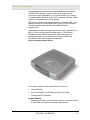
Section 1:Overview
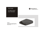
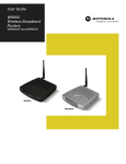
Congratulations on purchasing the Motorola Ethernet Broadband
Router BR700. With this router you have entered the world of
convenience and independence. Your router enables you to set up
your own private network for your PCs to: access the Internet, share
a printer, even participate in online gaming.
With a built-in firewall and Network Address Translation (NAT), your
Internet connection is robust and secure, giving you the security to
use the Internet without fear that your network might be
compromised.
Upgradeable firmware also keeps the router’s control software up-todate, so you’ll know you have the latest version. The Ethernet
Broadband Router BR700 captures the latest technology in a
package that stays current, protects your home network, and
provides you easy home network management.
Ethernet Broadband Router BR700
Your router is really several products built into one unit:
!
Internet Sharing
!
4-port Full Duplex 10/100 Ethernet Switch and Router
!
Firewall and NAT protection
Internet Sharing
Enables you to share your broadband Internet connection with all
of your Ethernet connected computers and devices.
SECTION 1, OVERVIEW
1-1
SECTION 1
OVERVIEW
4-port Full Duplex 10/100 Ethernet Switch and Router
Enables connection of up to 4 PCs. The routing function enables
each of your networked PCs to share files and printers as well.
Firewall and NAT Protection
Protection against Internet intruders is crucial and the built-in
Firewall will protect you. Of course, the product also supports
Virtual Private Network (VPN) connections through the firewall,
allowing you the freedom to connect when you need it.
Also supported are the NAT and MAC filtering protocols, giving
you the choice to share your Internet connection with only those
whom you designate.
Your Motorola Ethernet Broadband Router BR700 protects and
connects you by sharing your files, Internet connection, printers and
multi-player games, all in one great unit.
Features
The BR700 has the following features:
1-2
!
CD-ROM based Installation Wizard to provide easy installation
!
Web-based configuration of features using any web browser
!
Firmware upgrade to stay current with latest specifications
!
Firewall protection with NAT translation, IP and MAC address
filtering
!
A built-in DHCP server to easily configure a private Local Area
Network (LAN)
!
Virtual Private Network (VPN) pass-through allowing remote
connection with your corporate network
SECTION 1, OVERVIEW
OVERVIEW
SECTION 1
Understanding Your User Guide
The User Guide is subdivided into the following sections:
Overview
Provides a general introduction for using your
product, the type of technology used, and
recommended practices for using it.
Installation
It is assumed that you will use the Installation
Wizard on the CD-ROM to setup your unit. If not,
this section provides details on getting your unit up
and running.
Once you have completed this section, your unit
will be active and ready to work.
Configuration
Provides descriptive details for using the
Configuration Utility to manage your unit.
Glossary
List of terms and acronyms
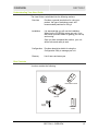
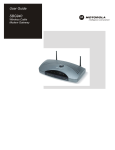
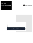
Box Contents
Your box contains the following:
CD-ROM
Base Station Stand
BR700
Power
Supply
SECTION 1, OVERVIEW
Quick Start
Guide
1-3
SECTION 1
OVERVIEW
Understanding Functions
The various technologies and features utilized by your router require
some explanation so you can make the correct choices when
configuring your router.
Router
Routers connect two networks together, or in your case, your home
network with the Internet (which can be thought of as a very large
network). Routers provide bandwidth security by keeping data out of
your home network where it does not belong.
The router’s Firewall inspects each packet of data as it flows through
the port before delivering it to the appropriate PC. Network Address
Translation (NAT) translates one set of IP addresses, usually private,
to another set, usually public. This is how your network remains
protected and private on the Internet.
TCP/IP
Transmission Control Protocol/Internet Protocol (TCP/IP) comprises
the backbone of the Internet. IP moves packets of data between
nodes while TCP verifies delivery from client to server. Every device
you hook up to your router identifies itself with an IP address. You
are able to assign devices on your network with either a static or
dynamically assigned IP address.
Static IP Address
A static IP address is a fixed address that is assigned manually to a
device on the network. Static IP addresses must be unique and
cannot be shared, therefore they are used in situations where the
address should never change, like print servers or PC servers.
If using your router to share an Internet connection, your Internet
Service Provider (ISP) might have assigned you a static IP address,
which you will use when configuring your router. See more
information in Configuration.
Dynamic IP Address
A dynamic IP address is a temporary IP number, dynamically or
randomly generated by a DHCP server. The address lasts only as
long as the server allots, usually in the space of a day or two. When
the IP address expires, the client is automatically reassigned a new
IP address, ensuring smooth communication.
If using your router to share an Internet connection, your ISP might
have assigned you a dynamic IP address, which you use when
configuring your router. See more information in Configuration.
1-4
SECTION 1, OVERVIEW
OVERVIEW
SECTION 1
DHCP Server
A Dynamic Host Configuration Protocol (DHCP) Server assigns IP
addresses to clients connected to the router. Client is the general
term used to describe any device that connects with your unit. The
client (PC, gaming device, etc.) is automatically assigned an IP
address every time a device is added to your network, freeing you
from manually assigning IP addresses.
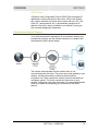
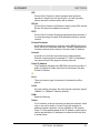
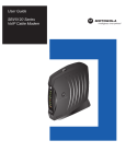
Simple Home Network Diagram
Your router serves as the centerpiece of your network, allowing you
to share files, printers, and the Internet connection. A sample Local
Area Network (LAN) is shown below:
The Internet communicates with the modem which in turn
communicates with the router. The router acts as the gateway to your
network, sending information to whichever device asks for
information, be it from requests for Internet access to file sharing to
multiplayer games. The router controls the information for your
network, intelligently routing the information to its required destination
while at the same time protecting your network from the public
domain.
SECTION 1, OVERVIEW
1-5
SECTION 1
OVERVIEW
Router Physical Description
The following sections describe the physical characteristics of your
unit.
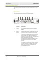
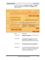
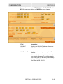
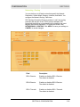
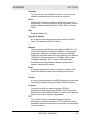
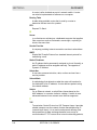
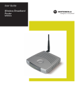
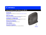
Back of Router
The following illustration shows the BR700 back panel:
1
2
3
4
5
6
7
4
3
2
1
WAN
Reset
Power
LAN
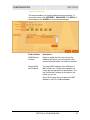
Feature
Description
1
Power
The receptacle where you plug in the power
adapter.
2
Reset
Button
A dual-function button. It either resets your unit
or resets the unit to the default login settings.
If the router is experiencing trouble connecting
to the Internet, briefly press and release the
Reset button to reset the router. This retains the
router’s configuration information.
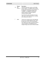
To reset the unit to the factory defaults, press
and hold the Reset button for more than 5
seconds.
This clears the router’s user settings, including
User ID, Password, IP Address, and Subnet
mask. Refer to Section3:Configuration for
re-configuring the router.
1-6
SECTION 1, OVERVIEW
OVERVIEW
SECTION 1
3-6
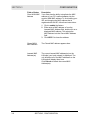
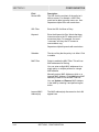
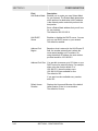
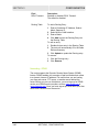
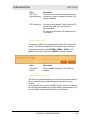
Feature
Description
LAN
Ports 1-4
These four ports can connect your LAN with
Ethernet cables. This enables communication
among clients, such as PCs or print servers, on
the network. The LAN ports support either
10-BASE-T or 100-BASE-T transmission
speeds as well as straight-through and
crossover Ethernet cables.
Any of these four ports can also serve as an
uplink port to other network devices, enabling
you to extend your network.
7
WAN
Connect your modem to your router using this
port with your supplied Ethernet cable. This is
the only port you can use for this procedure.
This enables your router to access the Internet.
The port supports 10/100 Mbps as well as
straight-through and crossover Ethernet cables.
SECTION 1, OVERVIEW
1-7
SECTION 1
OVERVIEW
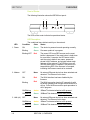
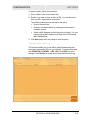
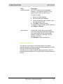
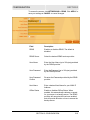
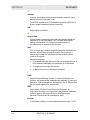
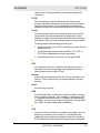
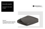
Front of Router
The following illustration shows the BR700 front panel:
1
2
3
4
3
2
1
M
P
od
em
Local Network
er
ow
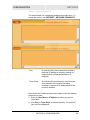
The LEDs of the router indicate its operational status.
LED Description
The underlined items indicate activity on the network.
LED
1. Power
2. Modem
3. LAN (x4)
1-8
Condition
Color
Status
ON
Green
The device is powered on and operating normally.
Blinking
Green
Firmware update is in progress.
Blinking/OFF
Red
The power LED turns RED as soon as the reset
button is depressed. If the reset button is held down
for more than 5 seconds, the LED starts to blink
and the router’s default user name, password,
private LAN IP address, and private subnet mask
address will be restored. The LED then turns off
until the reset button is released. The power LED
keeps blinking RED if the firmware is corrupted,
indicating the firmware needs to be restored.
OFF
None
No external Ethernet device has been attached and
detected. The Ethernet link is down.
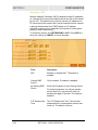
ON
Red
The WAN interface has been disabled by the
firmware.
Blinking
Red
The WAN connection has lost IP connectivity with
its default gateway even though the Ethernet link is
still up. Or the WAN connection repair procedure is
still in progress.
ON/Blinking
Amber 10BaseT link detected/active traffic present.
ON/Blinking
Green
100BaseT link detected/active traffic present.
OFF
None
No external Ethernet device has been attached and
detected. The Ethernet link is down.
ON/Blinking
Amber 10BaseT link detected/active traffic present.
ON/Blinking
Green
100BaseT link detected/active traffic present.
SECTION 1, OVERVIEW
Section 2:Installation
To get your network up and running:
!
Setup your hardware.
!
Insert the CD-ROM for Product Setup. Follow the prompts.
If you prefer to setup the router’s software manually, refer to the
Manual Software Setup found later in this section.
The following sections provide detailed instructions for completing
these tasks.
Hardware Setup
Hardware setup includes:
!
Physical Installation: where you physically place your unit.
!
Electrical Connection: how to connect the power cord.
Router Physical Installation
You can install the router in various physical orientations –
horizontally, vertically, or hung on the wall. Your own needs
determine the best placement.
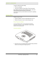
Horizontal Installation
1
Place the router in the desired location and follow the procedures
below for connecting and configuring the unit.
SECTION 2, INSTALLATION
2-1
SECTION 2
INSTALLATION
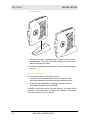
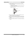
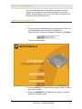
Vertical Installation
1
To use the router in a vertical position, insert the router into the
supplied base. The router’s foot slides snugly into a notch in the
base to keep the unit stable.
2
Follow the installation procedures for connecting and configuring
the unit.
Wall Mount Installation
If you mount the router on the wall, you must:
!
Locate the unit as specified by the local or national codes
governing residential or business communications services.
!
Follow all local standards for installing a network interface
unit/network interface device (NIU/NID).
If possible, mount the router to concrete, masonry, a wooden stud, or
other very solid wall material. Use anchors if necessary; for example
if you must mount the unit on drywall.
2-2
SECTION 2, INSTALLATION
INSTALLATION
SECTION 2
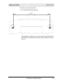
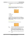
To mount your router on the wall:
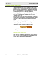
1
Print the Wall Mounting Template.
5.1”
[129.5mm]
The illustration is drawn at a one-to-one scale, which means that
when printed, it provides the exact dimensions required to mount
the unit.
SECTION 2, INSTALLATION
2-3
SECTION 2
INSTALLATION
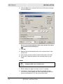
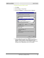
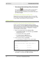
2
Click the Print icon or choose Print from the File menu to display
the Print dialog box:
Be sure you print the template at 100% scale and that Fit to page is
not checked in the Print dialog box.
3
Click OK.
4
Measure the printed template with a ruler to ensure that it is the
correct size.
5
Use a center punch to mark the center of the holes on the wall.
6
On the wall, locate the marks for the mounting holes you just
made.
WARNING!
Before drilling holes, check the structure for potential
damage to water, gas, or electric lines.
2-4
7
Drill the holes to a depth of at least 3.8 cm (1½ inches).
8
If necessary, seat an anchor in each hole. Use M5 x 38 mm
(#10-16 x 11/2 inch) screws with a flat underside and maximum
screw head diameter of 10.5 mm to mount the router.
SECTION 2, INSTALLATION
INSTALLATION
SECTION 2
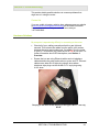
9
Using a screwdriver, turn each screw until part of it protrudes
from the wall, as shown:
!
There must be 4.0 mm (.16 inches) between the wall and the
underside of the screw head.
!
The maximum distance from the wall to the top of the screw
head is 7.6 mm (.3 in).
7.6 mm (.3 inches)
maximum
10.5 mm (.4 inches)
maximum
4.0 mm
10 Remove the two plastic feet, nearest to the LED panel, from the
bottom of the router to uncover the keyholes.
11 Place the router so the keyholes are above the mounting screws.
12 Slide the router down until it stops against the top of the keyhole
opening.
13 Follow the installation procedures for connecting and configuring
the unit.
SECTION 2, INSTALLATION
2-5
SECTION 2
INSTALLATION
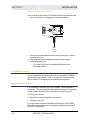
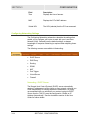
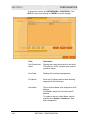
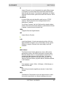
Electrical Connection to Router
Your router does not have an On/Off power switch and therefore will
only be powered on by plugging in the power adapter:
Reset
Power
LAN
To power
supply
1
Connect the power adapter to the router’s Power port, found on
the back of the unit.
2
Then plug the power adapter into a grounded and surge
protected power outlet.
!
The Power LED on the front panel lights green when
connected properly.
Easy Software Setup
Run the Installation Wizard program from the supplied CD-ROM to
quickly setup your network. Once your network is up and running,
refer to Section 3:Configuration for advanced configuration.
Manual Software Setup
If you’d prefer to manually setup your network, use this section to
configure it. This section details the physical connection of the router
to your network as well as the configuration needed by your PC.
To set up your network:
!
Physically connect and power on the router
!
Configure your PCs
If you don’t want to use the Installation Wizard from the CD-ROM,
follow the instructions below. For advanced configurations, refer to
Section 3:Configuration.
2-6
SECTION 2, INSTALLATION
INSTALLATION
SECTION 2
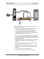
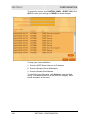
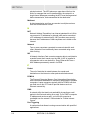
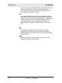
Connection to Router
ETHERNET
USB
CABLE
CUSTOMER S/N:BCDFGHJKLMNP
S/N: PPPPMMYJJJSSSSSCAABBCCCC
HFC MAC ID: ABCDEF012345
USB CPE MACID:ABDCEF012345
Reset
+12VDC
Power
LAN
4
3
2
1
WAN
When connecting your PC to the router, your PC must be installed
first with an Ethernet adapter.
You need two Ethernet cables for this procedure, one cable to connect the
router to the modem and one cable to connect a PC to the router.
1
A. If you have been running broadband to a single computer
before, unplug the Ethernet cable (that runs between your
modem and PC) from the back of your PC and plug it into the port
labeled WAN on the back of your router.
B. If you have not been running broadband to a single computer,
take one end of an Ethernet cable and plug it into the WAN port.
The WAN port is the only port that works for your connection from
the modem to the router.
2
Take the other end of the same cable and plug it into your cable
or DSL modem. You have now connected the router to the
modem.
3
To connect the PC to the router, use a different Ethernet cable
and plug it into your Ethernet port on your PC.
4
Use the other end of the same cable and plug it into one of the
LAN ports on your router. You have now connected your PC to
the router.
5
To connect more devices, repeat steps 4 and 5.
6
To configure the router, refer to Section 3: Configuration.
SECTION 2, INSTALLATION
2-7
SECTION 2
INSTALLATION
You have now completed the hardware installation. The next section,
Configure Your Computers, steps you through the various
configuration options needed for your PCs.
Configure Your Computers
Each computer that is going to be part of your network needs to “talk”
to the router. To do this, you have to configure each PC’s network
setting to automatically obtain an IP address. This section includes
information on configuring computers with the following operating
systems:
!
Windows 98SE
!
Windows ME
!
Windows 2000
!
Windows XP
Determine the operating system for each computer you are including
in your network and follow the steps to configure the network settings
for that PC.
2-8
SECTION 2, INSTALLATION
INSTALLATION
SECTION 2
Configuring Windows 98SE and ME
1
Click Start.
2
Select Settings > Control Panel.
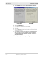
3
Double-click Network. The Network window is displayed:
4
On the configuration tab, select the TCP/IP line the for the
appropriate Ethernet adapter. There might be multiple adapters
installed – choose only the one that is configured for your
adapter. In the example above, a 3Com Ethernet adapter card is
installed and is the appropriate choice for this example.
SECTION 2, INSTALLATION
2-9
SECTION 2
INSTALLATION
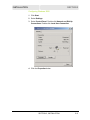
5
Click Properties. The TCP/IP Properties window is displayed:
Windows 98SE
Windows ME
6
Click the IP Address tab.
7
Select Obtain an IP address automatically.
8
Click OK.
9
Click the Gateway tab and check to make sure that the Installed
Gateway field is blank.
10 Click OK twice. Windows might ask for the Windows installation
disk. First check to see if the installation files are installed at
c:\windows\options\cabs. Otherwise, install your Windows CD
and follow the prompts.
11 Restart your computer to save your settings.
2-10
SECTION 2, INSTALLATION
INSTALLATION
SECTION 2
Configuring Windows 2000
1
Click Start.
2
Select Settings.
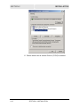
3
Select Control Panel. Double-click Network and Dial-Up
Connections. Double-click Local Area Connection.
4
Click the Properties button.
SECTION 2, INSTALLATION
2-11
SECTION 2
INSTALLATION
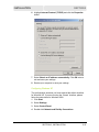
5
2-12
Ensure the box next to Internet Protocol (TCP/IP) is selected.
SECTION 2, INSTALLATION
INSTALLATION
SECTION 2
6
Highlight Internet Protocol (TCP/IP) and click the Properties
button.
7
Select Obtain an IP address automatically. Click OK twice to
exit and save your settings.
8
Restart your computer to save your settings.
Configuring Windows XP
This configuration assumes you have retained the default interface
for Windows XP. If you are running the ‘Classic’ interface, please
follow the instructions for Windows 2000.
1
Click Start.
2
Select Settings.
3
Select Control Panel.
4
Double-click Network and Dial-Up Connections.
SECTION 2, INSTALLATION
2-13
SECTION 2
2-14
INSTALLATION
5
Double-click Local Area Connection.
6
Click the Properties button.
7
Ensure the box next to Internet Protocol (TCP/IP) is selected.
SECTION 2, INSTALLATION
INSTALLATION
SECTION 2
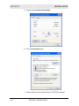
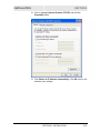
8
Click to highlight Internet Protocol (TCP/IP) and click the
Properties button.
9
Click Obtain an IP address automatically. Click OK twice to exit
and save your settings.
SECTION 2, INSTALLATION
2-15
SECTION 2
INSTALLATION
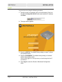
Log In
Log into the router using the following procedure:
1
Once the router is connected, open your web browser. Enter into
the URL field http://192.168.20.1 (the router’s default IP address)
and Enter.
2
The login screen appears.
3
Enter the USER ID. The default factory setting is “admin”, without
the quotation marks.
4
Enter the PASSWORD. The default factory setting is “motorola”,
without the quotation marks.
Once you have logged in, for security reasons you should change the User ID
and Password.
5
2-16
Click Log In to enter the Router’s Web-based Configuration
Utility.
SECTION 2, INSTALLATION
INSTALLATION
SECTION 2
Configure Your Basic Internet Settings
The following settings illustrate how to configure your router for
accessing the Internet. Detailed descriptions for using the web-based
utility follow this section.
1
Log into the router’s Configuration Utility. You are presented with
the Internet > Basic screen.
2
Starting at the Basic screen, select the Connection Mode your
ISP has indicated you need to use. Based on your connection
type, different areas become inaccessible, leaving you only the
appropriate fields to fill in the necessary information.
DHCP Configuration
The default setting for the router, DHCP is most commonly used for
cable modem connections. There is no configuration necessary for
this setting because the ISP automatically supplies the information.
Your ISP informs you if this is the connection to use.
1
Verify that DHCP is selected.
2
Click Apply to save the setting.
PPPoE
PPPoE (Point-to-Point Protocol over Ethernet) setting is most
commonly used for DSL modem connections. Your ISP informs you if
this is the connection to use.
1
From Connection Mode, select PPPoE.
2
In the PPP User Name field, enter the PPP User Name supplied
by your ISP.
3
In the PPP Password field, enter the PPP Password supplied by
your ISP.
4
Optionally, you might have to enter the PPP Service Name into
this field. Enter the information supplied by your ISP.
5
Click Apply to save the setting, or, if you want to start over, click
Cancel.
SECTION 2, INSTALLATION
2-17
SECTION 2
INSTALLATION
Static IP
If you are required to use a permanent IP address for connecting to
the Internet, then select Static IP. Your ISP informs you if this is the
connection to use.
1
From Connection Mode, select Static IP.
2
In the IP Address field, enter the IP Address supplied by your
ISP.
3
In the Subnet Mask field, enter the Subnet Mask supplied by
your ISP.
4
In the Default Gateway field, enter the values supplied by your
ISP.
5
In the Primary DNS field, enter the values supplied by your ISP. If
necessary, enter secondary or tertiary DNS values into the
Secondary or Third DNS fields.
6
Click Apply to save the setting, or, if you wish to start over, click
Cancel.
PPTP
Point to Point Tunneling Protocol (PPTP) is a service commonly
found in Europe.
2-18
1
From Connection Mode, select PPTP.
2
In the PPP User Name field, enter the PPP User Name supplied
by your ISP.
3
In the PPP Password field, enter the PPP Password supplied by
your ISP.
4
In the PPTP Client IP field, enter the PPTP Client IP address
supplied by your ISP.
5
In the PPTP Server IP field, enter the PPTP Server IP address
supplied by your ISP.
6
Click Apply to save the setting, or, if you wish to start over, click
Cancel.
SECTION 2, INSTALLATION
Section 3:Configuration
You can use the information in this section to modify the router’s
settings. For example you can customize features for your home
network, change settings such as your user name or password, view
the status of the network, and more.
Using the Configuration Utility
Log In
1
Once the router is connected, open your web browser. Enter into
the URL field the router’s IP address. The default is
http://192.168.20.1 (the router’s default IP address). Press Enter.
The login screen appears.
2
Enter the USER ID. The default factory setting is “admin”, without
the quotation marks.
3
Enter the PASSWORD. The default factory setting is “motorola”,
without the quotation marks.
SECTION 3, CONFIGURATION
3-1
SECTION 3
CONFIGURATION
4
Click LOG IN to enter the Router’s Web-based Configuration
Utility.
Navigation
Each of the following subsections provides descriptions for the
components of the router’s Configuration Utility – accessible from a
web browser. These sections include:
!
Internet
!
Parental Control
!
Networking
!
Control Panel
To navigate, click on a major section and then the associated
subsection. For example, to adjust the time setting, click CONTROL
PANEL on the left, then TIME tab at top on the right. The Web-based
Configuration Utility uses Javascript. Your web browser Javascript
needs to be enabled.
Help, Restart, and Log Out
Click on the appropriate command to execute the action.
Help
If assistance is required in using the router, click on Help.
Restart
To restart your session with the Configuration Utility, click
on Restart. If you see Restart flashing, the change you
have made requires that you restart the unit.
For convenience, it is recommended that you finish
all of your configuration changes and then restart the
unit.
Log Out
3-2
To logout out of the router’s Configuration Utility, click on
Log Out.
SECTION 3, CONFIGURATION
CONFIGURATION
SECTION 3
Configuring Internet Settings
These screens enable you to configure your Internet settings:
!
Basic
!
Advanced
!
Network Diagnostic
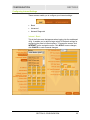
Internet - Basic
This is the first screen that appears when logging into the web-based
utility. It enables you to adjust a large variety of the basic settings for
configuring the router’s Internet options. To access the screen, click
INTERNET on the navigation menu. Click APPLY to save changes,
click CANCEL to undo unsaved changes.
SECTION 3, CONFIGURATION
3-3
SECTION 3
CONFIGURATION
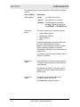
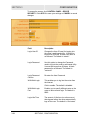
The following table provides descriptions for the fields in the Basic
window:
Field or Button
WAN Interface
Description
Active
Your WAN link is active.
Inactive
Your WAN link is not active.
Disabled The WAN interface has been
disabled. This can be altered on
the INTERNET > ADVANCED tab.
Connection
Mode
The router supports four connection modes:
! Cable Modem (DHCP)
! DSL Modem (PPPoE)
! Static Assigned
! PPTP
Select the appropriate connection method for
your ISP (Internet Service Provider).
Based on which connection mode you select,
different areas are grayed out (become
inaccessible), leaving you only the appropriate
fields to fill in.
For details on each Connection Mode, refer to
Section 2:Installation.
Connection
Repair
Click to perform a connection repair operation.
The type of repair depends on the connection
mode selected.
For example, for DHCP, the router issues a
request for a new IP address from the ISP’s
DHCP server.
Connection
Status
Provides current information about the
connection status of the router.
Click Refresh to update the status.
3-4
SECTION 3, CONFIGURATION
CONFIGURATION
SECTION 3
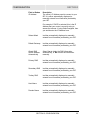
Field or Button
Description
IP Address
The router’s IP Address used to connect to your
ISP. It is either automatically displayed or
manually entered from information provided by
your ISP.
For example, if DHCP is selected, this is the IP
Address that your router is currently using to
access the Internet. If using Static Assigned, then
you would enter the IP Address here.
Subnet Mask
Is either automatically displayed or manually
entered from information provided by your ISP.
Default Gateway
Is either automatically displayed or manually
entered from information provided by your ISP.
Obtain DNS
Server Address
Automatically
Select Yes to obtain the DNS information
automatically, or No to enter the information
manually.
Primary DNS
Is either automatically displayed or manually
entered from information provided by your ISP.
Secondary DNS
Is either automatically displayed or manually
entered from information provided by your ISP.
Tertiary DNS
Is either automatically displayed or manually
entered from information provided by your ISP.
Host Name
Is either automatically displayed or manually
entered from information provided by your ISP.
Domain Name
Is either automatically displayed or manually
entered from information provided by your ISP.
SECTION 3, CONFIGURATION
3-5
SECTION 3
CONFIGURATION
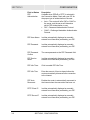
Field or Button
Description
PPP
Authentication
Available when PPPoE or PPTP is selected in
the Connection Mode. Check with your ISP for
the proper type of authentication to choose:
!
!
!
3-6
Auto – The router will offer PAP or CHAP to
the server, and the server will determine
which PPP Authentication to use.
PAP – Password Authentication Protocol.
CHAP – Challenge Handshake Authentication
Protocol.
PPP User Name
Is either automatically displayed or manually
entered from information provided by your ISP.
PPP Password
Is either automatically displayed or manually
entered from information provided by your ISP.
PPP Password
Confirm
The same password as the PPP Password field.
PPP Service
Name
Is either automatically displayed or manually
entered from information provided by your ISP.
PPP Idle Timer
Click to enable PPP Idle Time.
PPP Idle Time
Enter the amount of time to elapse before the
router automatically disconnects the connection
to the Internet.
PPP Auto
Reconnect
Enables the router to automatically reconnect to
the Internet when the connection has been cut.
PPTP Client IP
Is either automatically displayed or manually
entered from information provided by your ISP.
PPTP Server IP
Is either automatically displayed or manually
entered from information provided by your ISP.
SECTION 3, CONFIGURATION
CONFIGURATION
SECTION 3
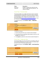
Internet - Advanced
This screen enables you to adjust additional Internet settings. To
access the screen, click INTERNET > ADVANCED. Click APPLY to
save changes, click CANCEL to undo unsaved changes.
Field or Button
Description
WAN Ethernet
Interface
Select to enable the link to the Internet. By
disabling this feature, your connection to the
Internet is disconnected. The default is enabled.
Factory WAN
MAC Address
The default MAC address of the WAN port. A
MAC address is a 12-digit code assigned to a
unique piece of hardware for identification. You
can find the MAC Address on the label on the
bottom of your unit.
Some ISPs require that you register the MAC
address of your PC’s network adapter.
SECTION 3, CONFIGURATION
3-7
SECTION 3
CONFIGURATION
Field or Button
Description
Clone WAN MAC
Address
Your router has the ability to duplicate the MAC
address of your PC’s network adapter into the
router’s WAN MAC address. To avoid calling your
ISP and changing the MAC address that is
registered with the ISP, follow these instructions:
1
2
3
Click to enable the feature.
Either enter a MAC address or from the
Learned MAC Address field, double-click on a
displayed MAC address. This selects the
MAC Address into the Cloned MAC Address
field.
Click APPLY to clone the address.
Cloned WAN
MAC Address
The Cloned MAC address appears here.
Learned MAC
Address(es)
The current learned MAC address(es) on the
LAN side (your local network) is displayed. The
unit will detect all of the MAC addresses on the
LAN and will display them here.
Click Refresh to obtain the current MAC
Address(es).
3-8
SECTION 3, CONFIGURATION
CONFIGURATION
SECTION 3
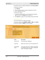
Internet - Network Diagnostic
This screen helps you troubleshoot problems that might occur. To
access the screen, click INTERNET > NETWORK DIAGNOSTIC.
Ping
An Internet utility used to determine whether a
particular IP address is online by sending out
a packet (block of data) and waiting for a
response.
Trace Route
An Internet utility that traces the route from the
client machine to the remote host being
contacted. It reports the IP addresses of all the
routers in between.
Both utilities are initiated using the same method. Use the following
procedure for each:
1
Enter the Host Name or IP Address for which you require
information.
2
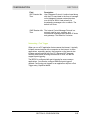
Click Ping or Trace Route to activate the utility. The results of
your query are displayed.
SECTION 3, CONFIGURATION
3-9
SECTION 3
CONFIGURATION
Configuring Parental Control Settings
The settings described in this section enable you to tailor the type of
content you want to allow your router to access. You create a policy
that defines content access. Each policy can be associated with all
the PCs the router supports. For example, a “Kids Policy” could be
defined and assigned to all PCs that a child can access.
Also, a single policy can encompass multiple time schedules and
multiple periods that can be assigned to any given PC. For example,
a PC might be associated with a “Weekday Kids Policy” and a
“Weeknight Parent” policy.
Each policy uses a content filter keyword list, meaning any sites with
content containing these keywords are blocked. Each policy can also
use a URL list that contains URLs that are specifically denied or
allowed.
In this way, it is possible to explicitly block access to certain sites or
to create a “walled garden” in which access is only granted to a
select group of websites.
The following screens are available in Parental Control:
!
Content Policy
!
URL Log
Parental Control - Content Policy
From this screen you are able to define up to ten Policies that define
what, when, and where the router accesses. Detailed directions for
creating a policy appears after the field descriptions.
3-10
SECTION 3, CONFIGURATION
CONFIGURATION
SECTION 3
To access the screen, click PARENTAL CONTROL > CONTENT
POLICY. Click APPLY to save changes, click CANCEL to undo
unsaved changes.
Field
Description
Content Policy
Enables or disables the Content Policy feature.
The default is disabled.
Policy Table
The defined Policies appear here. You can
Add, Update, and Remove Policies in the
table by selecting it and performing the action.
Policy Name
The Name of the policy, up to 32 characters.
You can enter up to ten different policies.
Allowed URL
The URL that the recipient of the policy is able
to access. For example, a Kid Policy would be
able to access: www.kids.com. Separate
multiple URLs with semicolons.
SECTION 3, CONFIGURATION
3-11
SECTION 3
CONFIGURATION
Field
Description
Denied URL
The URL that the recipient of the policy isn’t
able to access. For example, a Kid Policy
would not be able to access: www. xxx. com.
Separate multiple URLs with semicolons.
URL Filter
Enter the URL for Allow or Deny.
Keyword
Enter the Keyword to filter. Words that deny
Internet access to the PC whenever the PC
encounters them. For example, the word
“cormorant” will deny the PC access to
www.audubon.org.
Separate multiple Keywords with semicolons.
Schedule
The time of day that the policy is in effect. Click
to enable.
MAC Filter
Select to enable the MAC Filter. This will use
MAC addresses for filtering.
You can enter multiple MAC addresses for a
single policy or multiple policies for a single
MAC address.
Manually enter a MAC Address or click on a
Learned MAC Address. Click Add (below MAC
Address) to enter it into the MAC Filter list.
You can Update and Remove MAC Address
in the table by selecting it and performing the
action.
Learned MAC
Address(es)
3-12
The MAC address(es) discovered on the LAN
appear here.
SECTION 3, CONFIGURATION
CONFIGURATION
SECTION 3
To create a policy, follow this procedure:
1
Enter a Name in the Policy Name field.
2
Decide if you want to Allow or Deny a URL. You can add more
than one URL, separated by semicolons.
The following selections are optional for the policy:
3
!
Enter a Keyword filter.
!
Enable a time-based policy by enabling and selecting the
time/date options.
!
Select a MAC Address to which the policy will apply. You can
easily select a MAC Address by clicking one in the Learned
MAC Address field.
Click Add (below the Policy table) to save the policy.
Parental Control - URL Log
This screen enables you to view URLs (web site addresses) that
have been accessed by PCs on your network. To access the screen,
click PARENTAL CONTROL > URL LOG. Click APPLY to save
changes. Click Refresh to update the list with the latest URL Log.
SECTION 3, CONFIGURATION
3-13
SECTION 3
CONFIGURATION
Field
Description
Time
Displays the time of access.
MAC
Displays the PC’s MAC address.
Visited URL
The URL (website) that the PC has accessed.
Configuring Networking Settings
The Configuring Networking subsections describe the settings that
enable you to configure your router to work with your Local Area
Network (LAN). Generally use the default settings, as deeper
knowledge of computer networking is required when adjusting these
settings.
The following screens are available in Networking:
!
DHCP Server
!
DNS Proxy
!
Routing
!
DDNS
!
NAT
!
Port Trigger
!
Virtual Server
!
Firewall
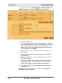
Networking - DHCP Server
The Domain Host Control Protocol (DHCP) server automatically
assigns IP addresses to all the clients on your network, relieving you
of the responsibility for issuing separate IP addresses. It is highly
recommended that you administer your network using the DHCP
Server function. The PCs must be configured to “Obtain an IP
Address Automatically.” See the Installation section of this User
Guide for further details.
3-14
SECTION 3, CONFIGURATION
CONFIGURATION
SECTION 3
To access the screen, click NETWORKING > DHCP SERVER. Click
APPLY to save your settings or CANCEL to cancel changes.
Field
Description
LAN MAC
Address
Displays the LAN MAC address of the router.
This field cannot be edited.
LAN Private IP
Enables you to create your own private IP
network.
Enter an IP address string that you will use for
your network. Because it is a private network,
your router gives you the ability to choose any
string you prefer.
The default is 192.168.20.1
SECTION 3, CONFIGURATION
3-15
SECTION 3
CONFIGURATION
Field
Description
LAN Subnet Mask
Enables you to create your own Subnet Mask
for your network. The Subnet Mask determines
which portion of a destination LAN IP address
is the network portion and which portion is the
host portion.
Enter a Subnet Mask address that you will use
for your network.
The default is 255.255.255.0
LAN DHCP
Server
Enables or disables the DHCP server. You can
only run one DHCP server on your network.
The default is enabled.
Address Pool
Begins
Based on what is entered in the LAN Private IP
field, the number entered here is where the
router starts handing out IP numbers. So,
using the default IP address, the next number
provided would be 192.168.20.2.
Address Pool Size
You are able to reserve up to 253 slots on your
DHCP server for potential clients. For example,
when using the router’s default IP of
192.168.20.1, then all numbers up to
192.168.20.254 are available for use.
The default is 253.
If you want to make available every number,
enter 253.
Default Lease
Duration
3-16
Displays the Hours and Minutes of the default
lease duration. Enter in a new duration.
The default is 8 hours.
SECTION 3, CONFIGURATION
CONFIGURATION
SECTION 3
Field
Description
Reserved Leases
The DHCP reserves a set IP addresses.
However, if you require a specific IP for a
specific device, such as a print server:
To reserve a lease:
1
2
3
Enter a new MAC Address.
Enter the reserved IP Address.
Choose the duration type. If limited, enter
the lease duration value.
4 Click Add to reserve the lease.
To update or remove a lease, select it and then
click Update or Remove.
Active Leases
Displays the current clients that the DHCP
server has assigned IP addresses. Displaying
only active leases with the following: MAC
Address, IP address, Host Name, and the
duration of its lease.
Click Refresh to obtain the latest list.
Networking - DNS Proxy
This feature is used only on your Private network. The feature
translates domain or website names into Internet addresses or URLs
using the Domain Name System (DNS).
This feature can be used to add the mappings between a Static IP
Address and a Host Name. This is most useful for devices like printer
servers.
SECTION 3, CONFIGURATION
3-17
SECTION 3
CONFIGURATION
To access the screen, click NETWORKING > DNS PROXY. Click
APPLY to save your settings or CANCEL to cancel changes.
Field
Description
LAN Private Host
Name
Displays the current Host name for the router.
The default is “br700” (all lower case, without
quotation marks).
Host Table
Displays the Host Name assignments.
IP Address
Enter the IP Address that has been statically
assigned for the LAN device.
Host Name
This is the Host Name to be assigned to the IP
address.
Click Add to assign the Host Name and IP
address.
To update or remove a Host Name, select it
and then click Update or Remove the Host
Name assignment.
3-18
SECTION 3, CONFIGURATION
CONFIGURATION
SECTION 3
Networking - Routing
You can define up to 20 static routes that specify the Network
Destination, Subnet Mask, Gateway, Interface, and Metric. You
configure the Network Routing Table here.
RIP (Routing Information Protocol) versions 1 and 2 are routing
protocols that are part of the TCP/IP protocol standard. RIP
dynamically determines a route based on the smallest hop count
between source and destination. To access the screen, click
NETWORKING > ROUTING. Click APPLY to save your settings or
CANCEL to cancel changes.
Field
Description
RIPv1 Receive
Enables or disables RIPv1 Receive.
The default is disabled.
RIPv2 Receive
Enables or disables RIPv2 Receive.
The default is disabled.
RIPv1 Transmit
Enables or disables RIPv1 Transmit.
The default is disabled.
SECTION 3, CONFIGURATION
3-19
SECTION 3
CONFIGURATION
Field
Description
RIPv2 Transmit
Enables or disables RIPv2 Transmit.
The default is disabled.
Routing Table
To add a Routing Entry:
1
Enter a Destination IP Address, Subnet
Mask, Gateway IP.
2 Select WAN or LAN Interface.
3 Enter a Metric.
4 Click Add to enter the Routing Entry into
the Routing Table.
To edit an entry:
1
2
Double-click an entry in the Routing Table.
The entry will automatically fill in the fields.
Edit as necessary.
3 Click Update to update the Routing entry.
To remove:
1
2
Click the Routing entry.
Click Remove.
Networking - DDNS
The router supports the Dynamic Domain Name System (DDNS)
feature. DDNS enables you to assign a fixed host and domain name
to a dynamic Internet IP address. It is useful when you are hosting
your own web server, FTP server, or another server behind the
router. Before you can use this feature, you must sign up for DDNS
service at a DDNS service provider, such as www.dyndns.org or
www.changeip.com. Once you have signed up, write down your User
Name and Password from the service.
3-20
SECTION 3, CONFIGURATION
CONFIGURATION
SECTION 3
To access the screen, click NETWORKING > DDNS. Click APPLY to
save your settings or CANCEL to cancel changes.
Field
Description
DDNS
Enables or disables DDNS. The default is
disabled.
DDNS Server
Select the desired DDNS service provider.
User Name
Enter the User Name (up to 30 bytes) provided
by the DDNS provider.
User Password
Enter the Password (up to 30 bytes) provided
by the DDNS provider.
User Password
Confirm
Re-enter the Password provided by the DDNS
provider.
Host Name
Enter a desired Host Name for your WAN IP
Address.
Offline Status
Enable or disables Offline Status. When
enabled, this automatically redirects a request
for your server to a backup server. The DDNS
provider will recognize this has been enabled
and will provide direction on how to access the
backup server.
SECTION 3, CONFIGURATION
3-21
SECTION 3
CONFIGURATION
Networking - NAT
Network Address Translation (NAT) translates multiple IP addresses
on a private LAN to one public address that is sent out to the Internet
by your ISP. This adds a level of security since the IP address of a
PC connected to the private LAN is never transmitted on the Internet.
A gaming Demilitarized Zone (DMZ) allows one IP address
(computer or device) to be exposed to the Internet for online game
playing or video conferencing.
To access the screen, click NETWORKING > NAT. Click APPLY to
save your settings or CANCEL to cancel changes.
3-22
Field
Description
NAT
Enables or disables NAT. The default is
enabled.
Gaming DMZ
Device
Click to enable. The default is disabled.
My Gaming DMZ
Device
Enter the IP Address for your Gaming Device.
TCP Session Idle
Time
The TCP Session Idle Time. The time that
elapses before it is assumed the session has
timed out. The default is 8 hours.
For security purposes, turn off your gaming
device when not in use so that it does not
become the target of intrusion. The default is
disabled.
SECTION 3, CONFIGURATION
CONFIGURATION
SECTION 3
Field
Description
UDP Session Idle
Time
User Datagram Protocol. A method used along
with the IP to send data in the form of message
units (datagram) between network devices
over a LAN or WAN. Used primarily for
broadcasting messages over a network. The
default is 8 hours.
ICMP Session Idle The Internet Control Message Protocol is a
Time
protocol used for error, problem, and
informational messages sent between IP hosts
and gateways. The default is 5 minutes.
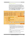
Networking - Port Trigger
When you run a PC application that accesses the Internet, it typically
initiates communications with a computer on the Internet. In some
applications, especially gaming, the computer on the Internet also
initiates communications with your PC. Because NAT does not
normally allow these incoming connections to occur, the BR700
supports port triggering.
The BR700 is configured with port triggering for some common
applications. You can also configure additional port triggers if
needed. Configuring port triggers for an application requires a Port
Trigger entry, explained below.
SECTION 3, CONFIGURATION
3-23
SECTION 3
CONFIGURATION
To access the screen, click NETWORKING > PORT TRIGGER. Click
APPLY to save your settings or CANCEL to cancel changes.
To add a Port Trigger entry:
1
Port Trigger Name: Enter the name of the application. There is a
limit of 32 characters for the name. Click to enable if you wish it to
become active. Otherwise, you can save the information and
enable it at later date. To enable at a later date, select the entry,
check enable, then click Update.
2
Outgoing Protocol: From the drop down box, select from TCP,
UDP, or Both.
3
Outgoing Port: Enter the From and To ranges (0 to 65535) for
your application.
4
Trigger Incoming Protocol: From the drop down box, select from
TCP, UDP, or BOTH.
5
Incoming Port Range: Enter continuous value(s) (0 to 65535),
separated by dashes, for your application. You can also enter
multiple non-continuous values, separated by semicolons.
6
Port Trigger Idle Time: Enter the elapsed time before the port
mapping closes.
To update or remove an entry, select it and then click Update or
Remove to perform the action.
3-24
SECTION 3, CONFIGURATION
CONFIGURATION
SECTION 3
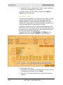
Networking - Virtual Server
The Virtual Server sets up an automatic inbound forwarding
mechanism for services running on your home computer, such as
web servers, email servers, or other specialized applications. When
you use this service, it is suggested that you use Static IP and not
DHCP, because the DHCP server may change the IP address during
usage. You may use DHCP by reserving an IP address.
The table below lists the current Port Forwarding rules. To access the
screen, click NETWORKING > VIRTUAL SERVER. Click APPLY to
save your settings or CANCEL to cancel changes.
To add a Virtual Server entry:
1
Virtual Server Name: Enter the name of the server. There is a
limit of 32 characters for the name. Click to enable if you wish it to
become active. Otherwise, you can save the information and
enable it at later date. To enable at a later date, select the entry
and then check enable.
2
Incoming Protocol: From the drop down box, select either TCP or
UDP.
3
Incoming Port: Enter the port value (0 to 65535).
4
Forwarding IP: Enter the IP Address of the server to which you
will forward.
5
Forwarding Port: Enter the port value (0 to 65535).
SECTION 3, CONFIGURATION
3-25
SECTION 3
CONFIGURATION
6
Schedule: This is an optional feature. Click to enable. Select the
time for the forwarding service to be active.
To update or remove an entry, select it and then click Update or
Remove to perform the action.
Networking - Firewall
This security device shields your network from the Internet. A firewall,
working closely with a router, examines each network packet to
determine whether to forward it toward its destination. The router
allows further customization of this packet sniffing by allowing you to
modify how and what can or cannot enter the router.
Additionally, the position of the rule within the table determines the
priority of the rule. For example, the first rule in the table applies, then
the second, etc. If the first rule deletes a ‘bad’ packet of information,
then the remaining rules are not invoked.
To access the screen, click NETWORKING > FIREWALL. Click
APPLY to save your settings or CANCEL to cancel changes.
To add a Packet Filter entry:
3-26
1
Filter Name: Enter the name of the packet filter. There is a limit of
32 characters for the name. Click to enable.
2
Filter Action: From the drop down box, select either Discard or
Forward.
SECTION 3, CONFIGURATION
CONFIGURATION
SECTION 3
3
Packet Direction: From the drop down box, select either Outgoing
or Incoming.
4
Packet Protocol: From the drop down box, select from TCP, UDP,
ICMP, or All.
5
Source and Destination: Enter the IP range and Port ranges
(0 to 65535).
6
Schedule: This is an optional feature. Click to enable. Select the
time for the packet filter to be active.
To update or remove an entry, select it and then click Update or
Remove to perform the action.
Configuring Control Panel Settings
The Control Panel screens enable administrative maintenance for
your router, such as changing your User Name/Password, updating
your firmware, or backing up your configuration.
The following screens are available in Control Panel:
!
Device Security
!
Firmware Update
!
Configuration Data
!
Time
!
UPnP
!
Event Log
Control Panel - Device Security
This screen enables you to change your User ID and password and
enables you to manage your router remotely.
SECTION 3, CONFIGURATION
3-27
SECTION 3
CONFIGURATION
To access the screen, click CONTROL PANEL > DEVICE
SECURITY. Click APPLY to save your settings or CANCEL to cancel
changes.
Field
Description
Login User ID
Changes the User ID used for logging into
the router’s web-based utility. It cannot be
longer than 63 bytes. A blank user name is
not allowed. The default is “admin”.
Login Password
Use this option to change the Password,
used to log into the router’s web based utility.
It cannot be longer than 63 bytes. A blank
password is not allowed. The default is
“motorola”.
Login Password
Confirm
Re-enter the User Password.
WAN Web Login
This enables you to log into the router from
the Internet.
Click to enable. The default is disabled.
3-28
WAN Web Login
Port
Enables you to specify different ports on the
router to allow remote login. The default is
8080.
Login Idle Time
The amount of idle time (no actions occur)
that elapses before the router automatically
logs off the user. The default is 10 minutes.
SECTION 3, CONFIGURATION
CONFIGURATION
SECTION 3
Field
Description
WAN Ping
Response
Enables a remote user to ping the router.
Select to enable WAN Ping response. The
default is disabled.
Control Panel - Firmware Update
This screen enables you to update the firmware (router’s hardware
control mechanism). Listed on this screen is the current version of
the Model Number, Serial Number, and Firmware Number; enabling
you to verify that you are running the most current version.
Access this website www.motorola.com/broadband/networking to check
for a firmware update.
To access the screen, click CONTROL PANEL > FIRMWARE
UPDATE.
To update the firmware:
1
Download the latest file to your computer from the website.
2
To locate the file you downloaded, type the path to the file or click
Browse and navigate to it.
3
Click Update to update the router with the selected firmware file.
Control Panel - Configuration Data
This screen enables you to save and restore your settings, which you
have currently configured for your router, to a file. You are also able
to reset the router to the factory default settings.
To access the screen, click CONTROL PANEL > CONFIGURATION
DATA.
SECTION 3, CONFIGURATION
3-29
SECTION 3
CONFIGURATION
To reset the router to its original configuration; click Factory Default.
To backup your settings,
1
Click Backup.
2
From the pop-up window, choose the destination for the file.
3
Enter a descriptive file name.
To restore your settings:
1
Locate the Configuration file on your computer by entering the
path to the file or click Browse and navigate to it.
2
Click Restore to reapply the saved settings with the selected file.
Control Panel - Time
This screen enables you to adjust time settings.
To access the screen, click CONTROL PANEL > TIME. Click APPLY
to save your settings or CANCEL to cancel changes.
3-30
Field
Description
Current Time
The current time is displayed.
Time Zone
Select your local time zone. The default is EST.
Auto Daylight
Adjust
If you want to have the unit adjust automatically
for Daylight Savings Time, select to enable this
feature. The default is enabled.
SECTION 3, CONFIGURATION
CONFIGURATION
SECTION 3
Field
Description
NTP Time
Synchronization
If you want the unit to automatically check the
current time, select to enable this feature. The
default is enabled.
NTP Server List
Lists the current Network Time Protocol (NTP)
servers from which you can choose for
synchronization.
Or, enter the host name or IP address for the
Time Server.
Control Panel - UPnP
This screen enables you to enable/disable Universal Plug and Play
(UPnP). This allows an application to smoothly map to the router.
To access the screen, click CONTROL PANEL > UPNP. Click
APPLY to save your settings or CANCEL to cancel changes.
Field
Description
LAN UPnP
Device
Click to disable this feature. The default is
enabled.
Control Panel - Event Log
The Event Log window enables you to view events (network activity,
when it occurred, and a textual description) that occur on your
network.
On this screen, you can enter the SMTP server name or IP address,
the recipient Email addresses, and the sender Email address so you
can be notified via email with the Event Log information.
SECTION 3, CONFIGURATION
3-31
SECTION 3
CONFIGURATION
To access the screen, click CONTROL PANEL > EVENT LOG. Click
APPLY to save your settings or CANCEL to cancel changes.
To setup your event notification:
1
Enter the SMTP Server Name or its IP address.
2
Enter the Recipient Email Address(es).
3
Enter the Sender Email Address.
To view Event Log information, click Refresh to view the latest
activity. The table lists the time of the event, the category, and a
textual description of the event.
3-32
SECTION 3, CONFIGURATION
Section 4:Troubleshooting
This section details possible solutions to common problems that
might occur in using the router.
Contact Us
If you are unable to locate a solution here, please access our website
at www.motorola.com/broadband/networking for the latest information.
You can also reach us 7 days a week, 24 hours a day at
1-877-466-8646.
Hardware Solutions
My computer is experiencing difficulty in connecting to the router.
!
Check all of your cabling connections that they are tight and
secured. This includes the cables from the wall to your modem,
between the router and modem, and, if available, from the router
to your PC. Ensure that your LEDs are not lit Red or not at all. For
further information about LED descriptions, see Section 1:
Overview.
!
Ensure that you are using Ethernet cables and not telephone
cables between the router and modem or router and PC. Ethernet
cables use a wider RJ-45 style plug using 8 wires where
telephone style plugs use the smaller RJ-11 style plug using
4 to 6 wires.
The plug on the left is RJ-45; the plug on the right is RJ-11 – use only
RJ-45.
SECTION 4, TROUBLESHOOTING
4-1
TROUBLESHOOTING
SECTION 4
!
Ensure that your Ethernet adapter is enabled. Check the System
Tray at the bottom right of your display to see an icon that looks
like a monitor.
You can click on this to see the status of
your Ethernet adapter. Also on your PC in Control Panel >
Network and Dial-Up Connections, you can examine the state of
your Ethernet adapter.
My broadband modem already uses a built-in router.
Because the two routers will cancel each other out, turning off the
NAT function in the modem will enable access for your router. Refer
to your modem’s documentation for further instructions.
Software Solutions
I would like to test to see if my Internet connection is alive.
For this, you will use the ping command to test the connection.
Before attempting, ensure that Obtain an IP address automatically
has been selected in the computer’s settings and that you have an IP
address assigned. Refer to Section 2: Configuration > Configure
Your Computers, for further details.
1
2
Open a command prompt by clicking Start and Run.
!
For Windows 98 and ME, in the Open field, type command
and press Enter or OK.
!
For Windows 2000 and XP, type cmd.
!
Or, navigate using your Start button to
Programs>Accessories>Command Prompt.
In the Command window, type ipconfig.
!
You should see an IP address for your network adapter:
Ethernet Adapter Local Area Connection:
Connection-specific DNS Suffix.: Example.example.example.com.
IP Address. . . . . . . . . . . . : 192.168.20.2
Subnet Mask . . . . . . . . . . . : 255.255.255.0
Default Gateway . . . . . . . . . : 192.168.20.1
3
4-2
In the Command window, type ping the Router’s IP address and
press Enter. For example type: ping 192.168.20.2.
SECTION 4, TROUBLESHOOTING
TROUBLESHOOTING
SECTION 4
There is a good possibility that the Default Gateway’s IP address
is the router’s IP address. You can verify the router’s IP address
on the Internet > Basic screen.
4
5
!
If you receive a reply (the first word will be Reply…), then
your computer is connected to the router. Proceed to Step 4.
!
If you do NOT receive a reply, try from a different computer to
verify that the first PC is not the cause of the problem.
In the Command window, type ping and your ISP’s default
gateway and press Enter. For example, type ping 192.168.20.1.
!
If you receive a reply (It might look something like this: Reply
from 216.109.125.72…), then your connection to the internet
is alive and well. You can verify the ISP’s IP address at the
Default Gateway field on the Internet > Basic screen.
!
If you do NOT receive a reply, try from a different computer to
verify that the first PC is not the cause of the problem.
If you cannot determine your ISP’s default gateway, ping
www.yahoo.com or another known web location.
I cannot access the Configuration Utility for the router.
!
Verify your Ethernet connection to the router.
!
Verify that the IP address of the PC being used to configure the
router is on the same network as the router’s configuration IP
address.
!
The IP address of your network adapter must be on the same
network and not a duplicate of any others on the network (for
example: 192.168.20.3 and using a subnet mask of
255.255.255.0 can be used to login to the router’s default IP
address of 192.168.20.1). Refer to Section 2: Configuration >
Configure Your Computers on how to adjust the IP address for
your PC.
!
Verify that you can ping the router on this IP address.
!
!
In the Command window, type ping and your router’s default
IP address and press Enter. For example, type:
ping 192.168.20.2.
!
If you have changed the factory configured default IP address
of the router, you will need to set your network adapter
accordingly.
Verify you are entering the correct URL in the browser. The
default is http://192.168.20.1. If you think you have changed the
IP address used to configure the router and cannot remember it,
you must reset the unit back to factory defaults. To do this, press
and hold the reset button for more the 5 seconds. This clears the
router’s user settings, including User ID, Password, IP Address,
and Subnet mask.
SECTION 4, TROUBLESHOOTING
4-3
TROUBLESHOOTING
SECTION 4
4-4
!
Once the router is reset to factory default setting, re-verify the
Ethernet connectivity and IP address issues.
!
Verify you are using the latest version of IE or Netscape. IE 5.2
and below are not supported.
SECTION 4, TROUBLESHOOTING
Section 5:Glossary
A
Adapter
A device or card that connects a computer, printer, or other
peripheral device to the network or to some other device. An
adapter connects a computer to a LAN.
Address translation
See NAT.
ASCII
The American Standard Code for Information Interchange refers
to alphanumeric data for processing and communication
compatibility among various devices; normally used for
asynchronous transmission.
B
Bandwidth
The transmission capacity of a medium in terms of a range of
frequencies. Greater bandwidth indicates the ability to transmit
more data over a given period of time.
bps
Bits Per Second
Broadband
A communications medium that can transmit a relatively large
amount of data in a given time period.
C
Cable Modem
A device providing data communications that connects a
computer to the Internet, via cable TV network.
Client
In a client/server architecture, a client is a computer that requests
files or services such as file transfer, remote login, or printing
from the server. Also called a CPE. Also see server.
Coaxial Cable
A type of cable consisting of a center wire surrounded by
insulation and a grounded shield of braided wire. The shield
minimizes electrical and radio frequency interference. Coaxial
cable has high bandwidth and can support transmission over long
distances.
SECTION 5, GLOSSARY
5-1
SECTION 5
GLOSSARY
CPE
Customer Premise Equipment: typically computers, printers, etc,
that are connected to the gateway at the subscriber location. CPE
can be provided by the subscriber or the cable service provider.
Also called a client.
Crossover Cable
A crossover cable is a cable that is used to interconnect two
computers by "crossing over" (reversing) their respective pin
contacts. A crossover cable is sometimes known as a null
modem.
D
Default Gateway
A routing device that forwards traffic not destined to a station
within the local subnet.
DHCP
A Dynamic Host Configuration Protocol server dynamically
assigns IP addresses to client hosts on an IP network. DHCP
eliminates the need to manually assign static IP addresses by
“leasing” an IP address and subnet mask to each client. It
enables the automatic reuse of unused IP addresses:
The BR700 is simultaneously a DHCP client and a DHCP server.
!
A DHCP server at the system headend assigns a public IP
address to the BR700.
!
The BR700 contains a built-in DHCP server that assigns
private IP addresses to clients.
DMZ
DeMilitarized Zone. This service opens one IP address to the
Internet, usually for online gaming, and acts as a buffer between
the Internet your network.
DNS
The Domain Name System is the Internet system for converting
domain names (like www.motorola.com) to IP addresses. A DNS
server contains a table matching domain names such as
www.motorola.com to IP addresses such as 192.169.9.1. When
you access the world-wide web, a DNS server translates the URL
displayed on the browser to the destination website IP address.
The DNS lookup table is a distributed Internet database; no one
DNS server lists all domain name to IP address matches.
Domain Name
A unique name, such as motorola.com, that maps to an IP
address. Domain names are typically much easier to remember
than are IP addresses. See DNS.
5-2
SECTION 5, GLOSSARY
GLOSSARY
SECTION 5
Download
To copy a file from one computer to another. You can use the
Internet to download files from a server to a computer.
Driver
Software that enables a computer to interact with a network or
other device. For example, there are drivers for printers, monitors,
graphics adapters, modems, Ethernet, USB, HPNA, and many
others.
DSL
Digital Subscriber Line
Dynamic IP Address
An IP address that is temporarily leased to a host by a DHCP
server. The opposite of Static IP Address.
E
Ethernet
The most widely used LAN type, also known as IEEE 802.3. The
most common Ethernet networks are 10Base-T, which provide
transmission speeds up to 10 Mbps, usually over unshielded,
twisted-pair wire terminated with RJ-45 connectors. Fast Ethernet
(100Base-T) provides speeds up to 100 Mbps. “Base” means
“baseband technology” and “T” means “twisted pair cable.”’
Each Ethernet port has a physical address called the MAC
address. Also see MAC address.
Event
A message generated by a device to inform an operator or the
network management system that something has occurred.
F
Firewall
A security software system on the BR700 that enforces an access
control policy between the Internet and the LAN for protection.
Firmware
Code that is written onto read-only memory (ROM) or
programmable read-only memory (PROM). Once firmware has
been written onto the ROM or PROM, it is retained even when the
device is turned off. Firmware is upgradeable.
FTP
File Transfer Protocol is a standard Internet protocol for
exchanging files between computers. FTP is commonly used to
download programs and other files to a computer from web pages
on Internet servers.
SECTION 5, GLOSSARY
5-3
SECTION 5
GLOSSARY
G
Gateway
A device that enables communication between networks using
different protocols. See also router.
The BR700 enables up to 253 computers supporting Ethernet to
share a single broadband Internet connection.
GUI
Graphical User Interface
H
Hexadecimal
A base-sixteen numbering system that uses sixteen sequential
numbers (0 to 9 and the letters A to F) as base units before
adding a new position. On computers, hexadecimal is a
convenient way to express binary numbers.
Host
In IP, a host is any computer supporting end-user applications or
services with full two-way network access. Each host has a
unique host number that combined with the network number
forms its IP address.
Host also can mean:
!
A computer running a web server that serves pages for one or
more web sites belonging to organization(s) or individuals
!
A company that provides this service
!
In IBM environments, a mainframe computer
I
ICMP
Internet Control Message Protocol is a protocol used for error,
problem, and informational messages sent between IP hosts and
gateways. ICMP messages are processed by the IP software and
are not usually apparent to the end-user.
IEEE
The Institute of Electrical and Electronics Engineers, Inc.
(http://www.ieee.org) is an organization that produces standards,
technical papers, and symposiums for the electrical and
electronic industries and is accredited by ANSI.
Internet
A worldwide collection of interconnected networks using TCP/IP.
5-4
SECTION 5, GLOSSARY
GLOSSARY
SECTION 5
IP
Internet Protocol is a set of standards that enable different types
of computers to communicate with one another and exchange
data through the Internet. IP provides the appearance of a single,
seamless communication system and makes the Internet a virtual
network.
IP Address
A unique 32-bit value that identifies each host on a TCP/IP
network. TCP/IP networks route messages based on the
destination IP address.
For a Class C network, the first 24 bits are the network address
and the final 8 bits are the host address; in dotted-decimal format
it appears “network.network.network.host.”
ISDN
Integrated Services Digital Network
ISP
Internet Service Provider
L
LAN
Local Area Network. A local area network provides a full-time,
high-bandwidth connection over a limited area such as a home,
building, or campus. Ethernet is the most widely used LAN
standard.
M
MAC Address
The Media Access Control address is a unique, 48-bit value
permanently saved in the ROM at the factory to identify each
Ethernet network device. It is expressed as a sequence of 12
hexadecimal digits printed on the unit’s label. You need to
provide the MAC address to the cable service provider. Also
called an Ethernet address, physical address, hardware address,
or NIC address.
MB
One megabyte; equals 1,024 x 1,024 bytes, 1,024 kilobytes, or
about 64 million bits.
Mbps
Million bits per second (megabits per second). A rate of data
transfer.
MTU
The Maximum Transmission Unit is the largest amount of data
that can be transmitted in one discrete message on a given
SECTION 5, GLOSSARY
5-5
SECTION 5
GLOSSARY
physical network. The MTU places an upper bound limit on the
size of a message that can be transferred by the network in a
single frame. Messages exceeding the MTU must be fragmented
before transmission, and reassembled at the destination.
Multicast
A data transmission sent from one sender to multiple receivers.
See also broadcast and unicast.
N
NAT
Network Address Translation is an Internet standard for a LAN to
use one set of IP addresses for internal traffic and a second set
of IP addresses for external traffic. NAT provides some security
because the IP addresses of LAN computers are invisible on the
Internet.
Network
Two or more computers connected to communicate with each
other. Networks have traditionally been connected using some
kind of wiring.
NIC
A Network Interface Card converts computer data to serial data in
a packet format that it sends over the LAN. A NIC is installed in
an expansion slot or can be built-in. Every Ethernet NIC has a
MAC address permanently saved in its ROM.
P
Packet
The unit of data that is routed between the sender and
destination on the Internet or other packet-switched network.
PCMCIA
The Personal Computer Memory Card International Association
sets international standards for connecting peripherals to portable
computers. Laptop computers typically have a PCMCIA slot that
can hold one or two PC Cards to provide features such as
Ethernet connectivity.
PING
A network utility that tests host reachability by sending a small
packet to the host and waiting for a reply. If you PING a computer
IP address and receive a reply, you know the computer is
reachable over the network. It also stands for “Packet Internet
Groper.”
Port Triggering
A mechanism that allows incoming communication with specified
applications.
5-6
SECTION 5, GLOSSARY
GLOSSARY
SECTION 5
PPP
Point-to-Point Protocol is used to transport other protocols,
typically for simple links over serial lines. It is most commonly
used to access the Internet with a dial-up modem.
PPPoE
Point-to-Point Protocol over Ethernet. Used by many DSL Internet
Service Providers for broadband connection.
PPTP
Point-to-Point Tunneling Protocol encapsulates other protocols. It
is a new technology to create VPNs developed jointly by several
vendors.
Private IP Address
An IP address assigned to a computer on the BR700 LAN by the
DHCP server for a specified lease time. Private IP addresses are
invisible to devices on the Internet. See also Public IP Address.
Protocol
A formal set of rules and conventions for exchanging data.
Different computer types (for example PC, UNIX, or mainframe)
can communicate if they support common protocols.
Public IP Address
The IP address assigned to the BR700 by the service provider. A
public IP address is visible to devices on the Internet. See also
Private IP Address.
R
RJ-11
The most common type of connector for household or office
phones.
RJ-45
An 8-pin modular connector; the most common connector type for
10Base-T or 100Base-T Ethernet networks.
ROM
Read-Only Memory.
Router
On IP networks, a device connecting at least two networks, which
may or may not be similar. A router is typically located at a
gateway between networks. A router operates on OSI network
Layer 3. It filters packets based on the IP address, examining the
source and destination IP addresses to determine the best route
to forward them.
SECTION 5, GLOSSARY
5-7
SECTION 5
GLOSSARY
A router is often included as part of a network switch. A router
can also be implemented as software on a computer.
Routing Table
A table listing available routes that is used by a router to
determine the best route for a packet.
RTS
Request To Send.
S
Server
In a client/server architecture, a dedicated computer that supplies
files or services such as file transfer, remote login, or printing to
clients. Also see client.
Service Provider
A company providing Internet connection services to subscribers.
SMTP
Simple Mail Transfer Protocol is a standard Internet protocol for
transferring e-mail.
Static IP Address
An IP address that is permanently assigned to a host. Normally, a
static IP address must be assigned manually. The opposite of
Dynamic IP Address.
Subscriber
A user who accesses television, data, or other services from a
service provider.
Subnet Mask
A methodology that determines what the router will examine for
the destination of an IP address. A router delivers packets using
the network address.
Switch
On an Ethernet network, a switch filters frames based on the
MAC address, in a manner similar to a bridge. A switch is more
advanced because it can connect more than two segments.
T
TCP
Transmission Control Protocol on OSI Transport Layer 4 provides
reliable transport over the network for data transmitted using IP
(network layer three). It is an end-to-end protocol defining rules
and procedures for data exchange between hosts on top of
connectionless IP. TCP uses a timer to track outstanding packets,
5-8
SECTION 5, GLOSSARY
GLOSSARY
SECTION 5
checks error in incoming packets, and retransmits packets if
requested.
TCP/IP
The Transmission Control Protocol/Internet Protocol suite
provides standards and rules for data communication between
networks on the Internet. It is the worldwide Internetworking
standard and the basic communications protocol of the Internet.
Tunnel
To place packets inside other packets to send over a network.
The protocol of the enclosing packet is understood by each
endpoint, or tunnel interface, where the packet enters and exits
the network. VPNs rely on tunneling to create a secure network.
Tunneling requires the following protocol types:
!
A carrier protocol, such as TCP, used by the network that the
data travels over
!
An encapsulating protocol, such as IPSec, L2F, L2TP, or
PPTP, that is wrapped around the original data
!
A passenger protocol, such as IP, for the original data
U
UDP
User Datagram Protocol. A method used along with the IP to
send data in the form of message units (datagram) between
network devices over a LAN or WAN.
Unicast
A point-to-point data transmission sent from one sender to one
receiver. This the normal way you access websites. See also
multicast.
UPnP
Universal Plug and Play
USB
Universal Serial Bus is a computer interface for add-on devices
such as printers, scanners, mice, modems, or keyboards. USB
1.1 supports data transfer rates of 12 Mbps and plug-and-play
installation. You can connect up to 127 devices to a single USB
port. USB 2.0 supports data rates of 480 Mbps.
V
VoIP
Voice over Internet Protocol is a method to exchange voice, fax,
and other information over the Internet. Voice and fax have
traditionally been carried over traditional telephone lines of the
PSTN (Public Switched Telephone Network) using a dedicated
SECTION 5, GLOSSARY
5-9
SECTION 5
GLOSSARY
circuit for each line. VoIP enables calls to travel as discrete data
packets on shared lines. VoIP is an important part of the
convergence of computers, telephones, and television into a
single integrated information network.
VPN
A virtual private network is a private network that uses “virtual”
connections (tunnels) routed over a public network (usually the
Internet) to provide a secure and fast connection; usually to users
working remotely at home or in small branch offices. A VPN
connection provides security and performance similar to a
dedicated link (for example, a leased line), but at much lower
cost.
W
WAN
A wide-area network provides a connection over a large
geographic area, such as a country or the whole world. The
bandwidth depends on need and cost, but is usually much lower
than for a LAN.
WWW
World Wide Web. An interface to the Internet that you use to
navigate and hyperlink to information.
5-10
SECTION 5, GLOSSARY
Visit our website at:
www.motorola.com/broadband
494263-001
07/03
MGBI