1
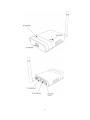
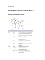
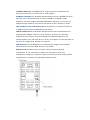
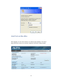
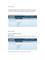
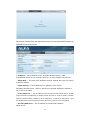
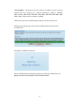
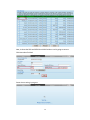
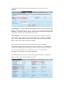
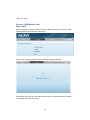
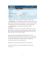
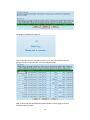
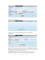
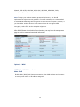
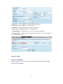
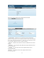
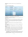
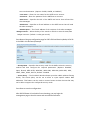
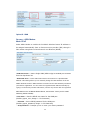
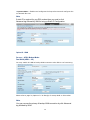
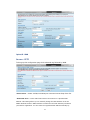
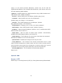
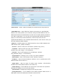
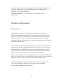
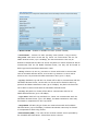
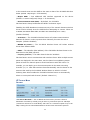
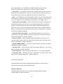
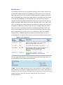
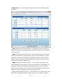
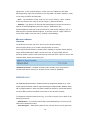
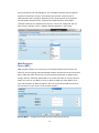
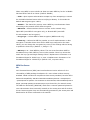
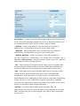
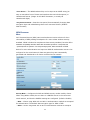
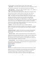
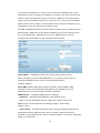
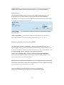
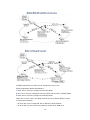
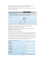
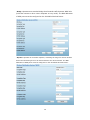
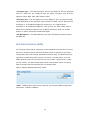
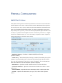
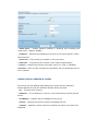
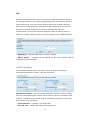
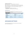
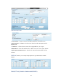
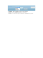
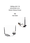
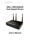
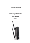
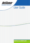
150Mbps 802.11N
3G Mobile Wireless Router
R36
User Guide
1
Contents
INTRODUCTION .................................................................................................... 3
KEY HARDWARE FEATURES ......................................................................... 3
DESCRIPTION OF CAPABILITIES .................................................................. 3
HARDWARE DESCRIPTION ........................................................................... 5
LED INDICATORS ............................................................................................. 7
INITIAL CONFIGURATION ...................................................................................... 9
CONNECTING TO THE LOGIN PAGE ............................................................. 9
HOME PAGE AND MAIN MENU .................................................................... 10
SETUP WIZARD.............................................................................................. 11
USB Adapter with Static IP ..................................................................... 11
USB Adapter with Dynamic IP ................................................................ 16
USB Adapter with PPOE........................................................................... 20
Using 3G Modem ..................................................................................... 21
Using DSL Connection ............................................................................. 25
Using DSL Modem & 3G Modem ............................................................ 26
Establishing PPTP ................................................................................... 27
Establishing L2TP .................................................................................... 28
Wireless Configuration ............................................................................................. 30
BASIC SETTINGS ........................................................................................... 30
ADVANCED SETTINGS................................................................................... 33
WLAN SECURITY ........................................................................................... 38
WIRELESS DISTRIBUTION SYSTEM (WDS) ................................................ 45
WI-FI PROTECTED SETUP (WPS)................................................................ 49
FIREWALL CONFIGURATION............................................................................... 51
MAC/IP/PORT FILTERING ............................................................................. 51
CURRENT FILTER RULES ............................................................................ 52
VIRTUAL SERVER SETTINGS (PORT FORWARDING) ........................... 52
CURRENT VIRTUAL SERVERS IN SYSTEM ................................................ 53
DMZ................................................................................................................ 54
ADVANCED SETTINGS .......................................................................................... 55
2
INTRODUCTION
The 150Mbps Wireless-N 3G Mobile Wireless Router
(R36) supports routing from an Internet Service Provider (ISP) connection (DSL
or cable modem) to a local network. It is simple to configure and can be up and
running in minutes.
KEY HARDWARE FEATURES
The following table describes the main hardware features of the 3G Mobile
Wireless Router.
Description
WAN Port: One 100BASE-TX RJ-45 port for connecting to the Internet.
LAN Port: One 100BASE-TX RJ-45 port for local network connections.
USB Port: One USB slot for a 3G or 3.5G modem and USB Wireless
Card WPS Button: To set up a secure connection to a wireless device.
Reset Button: For resetting the unit and restoring factory defaults.
LEDs: Provides LED indicators for Power, WAN port, LAN port, and WLAN status.
Mounting Options: Can be mounted on any horizontal surface such as a desktop
or shelf, or on a wall using two screws.
DESCRIPTION OF CAPABILITIES
◆ Internet connection through an RJ-45 WAN port.
◆ Local network connection through one 10/100 Mbps Ethernet port.
◆ DHCP for dynamic IP configuration.
3
◆ Firewall with Stateful Packet Inspection, client privileges, and NAT.
◆ NAT also enables multi-user Internet access via a single user account, and
virtual server functionality (providing protected access to Internet services such
as Web, FTP, e-mail, and Telnet).
◆ VPN passthrough (IPsec, PPTP, or L2TP).
◆ User-definable
application
sensing
tunnel
supports
applications
requiring
multiple connections.
◆ Easy setup and management through an easy-to-use web browser interface
on any operating system that supports TCP/IP.
◆ Compatible with all popular Internet applications.
APPLICATIONS Many advanced networking features are provided by the 3G Mobile
Wireless Router:
◆ Wired LAN — The 3G Mobile Wireless Router provides connectivity to wired
Ethernet devices, making it easy to create a network in small offices or homes.
◆ Internet Access — This device supports Internet access through a WAN connection.
Since many DSL providers use PPPoE, PPTP, or L2TP to establish communications with
end users, the 3G Mobile Wireless Router includes built-in clients for these protocols,
eliminating the need to install these services on your computer.
◆ Shared IP Address — The 3G Mobile Wireless Router provides
Internet access for up to 253 users using a single shared IP address
account. ◆ Virtual Server — If you have a fixed IP address, you can set the
3G Mobile Wireless Router to act as a virtual host for network address translation.
Remote users access various services at your site using a static IP address. Then,
depending on the requested service (or port number), the 3G Mobile Wireless
Router can route the request to the appropriate server (at another internal IP
address). This secures your network from direct attack by hackers, and provides
more flexible management by allowing you to change internal IP addresses
without affecting outside access to your network.
◆ DMZ Host Support — Allows a networked computer to be fully exposed to the
Internet. This function is used when NAT and firewall security prevent an Internet
application from functioning correctly.
◆ Security — The 3G Mobile Wireless Router supports security features that deny
Internet access to specified users, or filter all requests for specific services. WPA
(Wi-Fi Protected Access) and MAC filtering provide security over the wireless
network.
◆ Virtual Private Network (VPN) Passthrough — The 3G Mobile
Wireless Router supports the passthrough of three of the most commonly used VPN
4
protocols – IPsec, PPTP, and L2TP. These protocols allow remote users to
establish a secure connection to another network. If your service provider
supports VPNs, then these protocols can be used to create an authenticated and
encrypted tunnel for passing secure data over the Internet (that is, a traditionally
shared data network).
■
IPsec (Internet Protocol Security) — Encrypts and authenticates entire IP packets
and encapsulates them into new IP packets for secure communications between
networks.
■
PPTP (Point-to-Point Tunneling Protocol) — Provides a secure tunnel for remote
client access to a PPTP security gateway. PPTP includes provisions for call
origination and flow control required by ISPs.
■
L2TP (Layer 2 Tunneling Protocol) — Merges the best features of PPTP and the
Layer 2 Forwarding (L2F) protocol. Like PPTP, L2TP requires that the ISP’s routers
support the protocol.
HARDWARE DESCRIPTION
The 150Mbps Wireless-N 3G Mobile Wireless Router, from herein
refered to as 3G Mobile Wireless Router, connects to the Internet through
its RJ-45 WAN port. It connects directly to your PC or to a local area network
using its RJ-45 Fast Ethernet LAN port.
The 3G Mobile Wireless Router includes an LED display on the front panel for system
power and port indications that simplifies installation and network troubleshooting.
5
6
LED INDICATORS
The 3G Mobile Wireless Router includes four status LED indicators, as
described in the following figure and table.
7
ETHERNET WAN PORT A 100BASE-TX RJ-45 port that can be attached to an
Internet access device, such as a DSL or Cable modem.
ETHERNET LAN PORT The 3G Mobile Wireless Router has one 100BASE-TX RJ-45
port that can be attached directly to a PC or 10BASE-T/100BASE-TX LAN
segments. This port supports automatic MDI/MDI-X operation, so you can use
straight-through cables for all network connections to PCs, switches, or hubs.
3G & USB Wireless Card USB PORT Supports connection to a wireless cellular 3G
or USB Wireless Card for broadband Internet access.
POWER CONNECTOR The 3G Mobile Wireless Router must be powered with its
supplied power adapter. Failure to do so results in voiding of any warrantly
supplied with the product. The power adapter automatically adjusts to any
voltage between 100~240 volts at 50 or 60 Hz, and supplies 12 volts DC power to
the unit. No voltage range settings are required.
WPS BUTTON Press the WPS button to automatically configure the 3G Mobile
Wireless Router with other WPS devices in the WLAN.
REST BUTTON The Reset button is used to restore the factory default
configuration. If you hold down the button for 5 seconds or more, any
configuration changes you may have made are removed, and the factory default
configuration is restored to the 3G Mobile Wireless Router.
8
INITIAL CONFIGURATION
The 3G Mobile Wireless Router offers a user-friendly web-based
management interface for the configuration of all the unit’s features. Any
PC directly attached to the unit can access the management interface using a web
browser, such as Internet Explorer (version 6.0 or above).
CONNECTING TO THE LOGIN PAGE
It is recommended to make initial configuration changes by connecting a PC
directly to the 3G Mobile Wireless Router’s LAN port. The 3G Mobile Wireless Router has
a default IP address of 192.168.2.1 and a subnet mask of 255.255.255.0. You
must set your PC IP address to be on the same subnet as the 3G Mobile Wireless
Router (that is, the PC and 3G Mobile Wireless Router addresses must both start
192.168.2.x). To access the 3G Mobile Wireless Router’s management interface, follow
these steps:
1. Use your web browser to connect to the management interface using the
default IP address of 192.168.2.1.
2. Log into the interface by entering the default username ―admin‖ and password ―admin,‖
then click OK.
9
HOME PAGE AND MAIN MENU
After logging in to the web interface, the Status page displays. The Home
page shows the main menu and the method to access the Setup Wizard.
10
SETUP WIZARD
The Wizard is designed to help you configure the basic settings required to get
the 3G Mobile Wireless Router up and running. There are only a few basic steps
you need to set up the 3G Mobile Wireless Router and provide a connection.
Click on Easy Setup to bring up the wizard
Option #1 - WAN
SETTINGS – USB Wireless Adapter
Mode: Static IP
Enables support for AWUS wireless card as a WAN connection by selecting
Wireless Adapter from the Easy Setup page.
Screen shows saving in progress after 3G dongle has been selected.
11
USB
Select Static (Fixed IP) from the drop down menu from Connection Mode. Prepare an
available SSID after Site Survey.
◆ IP Address — The IP address of the 3G Mobile Wireless Router. Valid
IP addresses consist of four decimal numbers, 0 to 255, separated by periods.
◆ Subnet Mask — The mask that identifies the host address bits used for routing
to specific subnets.
◆ Default Gateway — The IP address of the gateway router for the
3G Mobile Wireless Router, which is used if the requested destination address is
not on the local subnet.
◆ Primary DNS Server — The IP address of the Primary Domain Name Server. A DNS
maps numerical IP addresses to domain names and can be used to identify network
hosts by familiar names instead of the IP addresses. To specify a DNS server, type
the IP addresses in the text field provided. Otherwise, leave the text field blank.
◆ Secondary DNS Server — The IP address of the Secondary Domain
Name Server.
12
◆ Security Mode — Specifies the security mode for the SSID. Select the security
method and then configure the required parameters. (Options: Disabled,
Open, Shared, WEP-AUTO, WPA-PSK, WPA2-PSK, WPA-PSK_WPA2-PSK, WPA,
WPA2, WPA1_WPA2, 802.1X; Default: Disabled
Click Site Survey to scan available network that you need to connect to it.
Click Rescan on the pop up screen to scan available network that you need
to connect to it.
Scanning for available wifi network.
Click on the SSID that you attempt to connect to it; VAP is the SSID that we are
going to connect in this example. Click Close when finished.
13
Now, it shows the SSID and BSSID that AWUS wireless card is going to connect.
Click Next when finished.
Screen shows saving in progress
14
Configure the SSID and Security Mode of the R36 Router, ALFA-Extend in this
example.
◆ Access Policy — The 3G Mobile Wireless Router provides a MAC address filtering
facility. The access policy can be set to allow or reject specific station MAC
addresses. This feature can be used to connect known wireless devices that may
not be able to support the configured security mode.
◆ Security Mode — Specifies the security mode for the SSID. Select the security
method and then configure the required parameters. (Options: Disabled,
Open, Shared, WEP-AUTO, WPA-PSK, WPA2-PSK, WPA-PSK_WPA2-PSK, WPA,
WPA2, WPA1_WPA2, 802.1X; Default: Disabled
NOTE: To keep your wireless network protected and secure, you should
implement the highest security possible. For small networks, it is recommended
to select WPA2-PSK using AES encryption as the most secure option. However, if
you have older wireless devices in the network that do not support AES
encryption, select TKIP as the encryption algorithm.
After R36 3G Router is back online from rebooting, you may login the management
page to check its status and associated information.
15
Option #1 - WAN
SETTINGS – USB Wireless Card
Mode: DHCP
Enables support for AWUS wireless card as a WAN connection by selecting
USB
Wireless Adapter from the Easy Setup page.
Screen shows saving in progress after 3G dongle has been selected.
Select Static (Fixed IP) from the drop down menu from Connection Mode. Prepare
an available SSID after Site Survey.
16
◆ Hostname — Specifies the host name of the DHCP client. (Default: R36)
◆ Primary DNS Server — The IP address of the Primary Domain Name Server. A DNS
maps numerical IP addresses to domain names and can be used to identify network
hosts by familiar names instead of the IP addresses. To specify a DNS server, type
the IP addresses in the text field provided. Otherwise, leave the text field blank.
◆ Secondary DNS Server — The IP address of the Secondary Domain
Name Server.
◆ Security Mode — Specifies the security mode for the SSID. Select the security
method and then configure the required parameters. (Options: Disabled,
Open, Shared, WEP-AUTO, WPA-PSK, WPA2-PSK, WPA-PSK_WPA2-PSK, WPA,
WPA2, WPA1_WPA2, 802.1X; Default: Disabled
NOTE: To keep your wireless network protected and secure, you should
implement the highest security possible. For small networks, it is recommended
to select WPA2-PSK using AES encryption as the most secure option. However, if
you have older wireless devices in the network that do not support AES
encryption, select TKIP as the encryption algorithm.
Click Site Survey to scan available network that you need to connect to it.
Click Rescan on the pop up screen to scan available network that you need
to connect to it.
17
Scanning for available wifi network.
Click on the SSID that you attempt to connect to it; VAP is the SSID that we are
going to connect in this example. Click Close when finished.
Now, it shows the SSID and BSSID that AWUS wireless card is going to connect.
Click Next when finished.
18
Screen shows saving in progress
Configure the SSID and Security Mode of the R36 Router, ALFA-Extend in
this example.
◆ Access Policy — The 3G Mobile Wireless Router provides a MAC address filtering
facility. The access policy can be set to allow or reject specific station MAC
addresses. This feature can be used to connect known wireless devices that may
not be able to support the configured security mode.
◆ Security Mode — Specifies the security mode for the SSID. Select the security
method and then configure the required parameters. (Options: Disabled, Open,
19
Shared, WEP-AUTO, WPA-PSK, WPA2-PSK, WPA-PSK_WPA2-PSK, WPA,
WPA2, WPA1_WPA2, 802.1X; Default: Disabled
NOTE: To keep your wireless network protected and secure, you should
implement the highest security possible. For small networks, it is recommended
to select WPA2-PSK using AES encryption as the most secure option. However, if
you have older wireless devices in the network that do not support AES
encryption, select TKIP as the encryption algorithm.
After R36 3G Router is back online from rebooting, you may login the management
page to check its status and associated information.
Option #1 – WAN
SETTINGS – USB Wireless Card
Mode: PPoE
Enable ADSL (PPoE) with Internet connection when USB wireless card connects
to access point where no IP address assigned.
20
◆ User Name — Sets the PPPoE user name for the WAN port.
(Default: pppoe_user; Range: 1~32 characters)
◆ Password — Sets a PPPoE password for the WAN port.
(Default: pppoe_password; Range: 1~32 characters)
◆ Verify Password — Prompts you to re-enter your chosen password.
◆ Operation Mode — Enables and configures the keep alive time and configures
the on-demand idle time.
Option #2 - WAN
SETTINGS - 3G Dongle
Enables support for a USB 3G modem as a WAN connection by selecting
from the Easy Setup page
21
3G dongle
Screen shows saving in progress after 3G dongle has been selected.
◆ Pin Code Protect — Enables the use of a PIN code (personal identification
number) to encrypt access to the 3G modem connection. Some service providers
do not require PIN code authentication. If a PIN code is not required for your 3G
or 3.5G modem, disable this function. (Default: Disabled)
◆ Dial Code — A dialled access code that connects the USB device to the service
provider.
◆ APN Service — The access point name (APN) that uniquely identifies the 3G or
3.5G service provider.
◆ User Name — The user name of the account registered with the 3G or
3.5G service provider.
◆ Password — The password of the account registered with the 3G or
3.5G service provider.
22
◆ Budget Control — Enables a monthly limit on time or total data. (Default:
Disabled)
If the Budget Control has been enabled,
◆ Budget Criterion — Specifies budget limits set by time or data.
Time Budget — Specify the amount of time (in hours) that can beused for the 3G
connection per month. (Range: 1~999 hours;
■
Default: 1 hour)
■
Data Budget — Specify how much Download/Upload data (in MBytes) is allowed
per month for the 3G connection. The drop-down list specifies if the data budget
is for download, upload, or download and upload. (Range: 3~4000 MBytes;
Default: 3 MBytes)
◆ Budget Policy — Specifies the action to take when budget limits have been
reached.
■
Action if Over Budget — Specifies the the action to take when a budget limit has
been exceeded:
■
Drop Current Connection — Immediately drop the current connection. (Default:
Enabled)
■
Disallow New Connection — Do not permit any new connections. (Default: Enabled)
■
Trigger by Limit Budget — Specifies the percentage of the time or data budget at
which to start sending E-mail alerts at the indicated time interval. When E-mail
alerts are enabled, be sure to configure the E-mail settings. (Default: 90% of
budget, E-mail Alerts disabled, recurring every 10 minutes)
◆ E-mail Settings — The unit can use SMTP (Simple Mail Transfer Protocol) to
send E-mail messages when triggered by the specified budget policy limits.
Mail SMTP Authentication — Specifies a user name and password for SMTP
23
■
server authentication. (Options: PLAIN, LOGIN, or Disabled.)
User Name — Enter the user name for the SMTP server account.
■ Password — Enter the password for the SMTP server account.
■
■
Mail Server — Specifies the URL of the SMTP mail server that will send the
alert messages.
■
Mail Sender — Specifies an E-mail address on the SMTP server that will send
the alert messages.
■ Mail Recipient — The E-mail address of the recipient of the alert messages.
◆ Budget Counter — Select the day of the month on which to reset the time/data
budget counters. (Default: 1st day per month)
Press Next to bring up configuration page for R36’s SSID and Security Mode, ALFA-3G
is the SSID in this document/example.
◆ Security Mode — Specifies the security mode for the SSID. Select the security
method and then configure the required parameters. (Options: Disabled,
Open, Shared, WEP-AUTO, WPA-PSK, WPA2-PSK, WPA-PSK_WPA2-PSK, WPA,
WPA2, WPA1_WPA2, 802.1X; Default: Disabled
◆ Access Policy — The 3G Mobile Wireless Router provides a MAC address filtering
facility. The access policy can be set to allow or reject specific station MAC
addresses. This feature can be used to connect known wireless devices that may
not be able to support the configured security mode.
Press Done to save the configuration.
After R36 3G Router is back online from rebooting, you may login the
management page to check its status and associated information.
24
Option #3 - WAN
SETTINGS – ADSL Modem
Mode: PPoE
Select ADSL Modem to enable the 3G Mobile Wireless Router IP address to
be assigned automatically from an Internet service provider (ISP) through a
DSL modem using Point-to-Point Protocol over Ethernet (PPPoE).
◆ WAN Connection — Select ―Single WAN (ADSL only)‖ for the WAN port connection
from the drop-down list.
■
Enable MAC Clone — Some ISPs limit Internet connections to a specified MAC
address. This setting allows you to manually change the MAC address of the 3G
Mobile Wireless Router's WAN interface to match the PC's MAC address provided to
your ISP for registration. You can enter the registered MAC address manually by
typing it in the boxes provided. Otherwise, connect only the PC with the registered
MAC address to the 3G Mobile Wireless Router, then click the ―Clone your PC’s MAC
Address.‖ (Default: Disable)
◆ User Name — Sets the PPPoE user name for the WAN port.
(Default: pppoe_user; Range: 1~32 characters)
◆ Password — Sets a PPPoE password for the WAN port.
(Default: pppoe_password; Range: 1~32 characters)
◆ Verify Password — Prompts you to re-enter your chosen password.
25
◆ Operation Mode — Enables and configures the keep alive time and configures the
on-demand idle time.
Note,
If static IP is required for your DSL modem then you need to click
Advanced tag followed by WAN to bring up Static IP Configuration
Option #3 - WAN
SETTINGS – ADSL Modem Mode:
Dual WAN (ADSL + 3G)
You may enable 3G USB as backup WAN connection when DSL is not functioning.
Please refer to page 20, Option #2: 3G Dongle, for setup detail on 3G modem.
Note,
You may reverse the primary & backup WAN connection by click Advanced
tag followed by WAN
26
Option #5 - WAN
SETTINGS – PPTP
To bring up this configuration page click Advanced tag followed by WAN.
◆ Ethernet Port — Select ―PPTP‖ for the WAN port connection from the drop-down list.
■
Enable MAC Clone — Some ISPs limit Internet connections to a specified MAC
address. This setting allows you to manually change the MAC address of the 3G
Mobile Wireless Router's WAN interface to match the PC's MAC address provided to
your ISP for registration. You can enter the registered MAC address manually by
27
typing it in the boxes provided. Otherwise, connect only the PC with the
registered MAC address to the 3G Mobile Wireless Router, then click the ―Clone your
PC’s MAC Address.‖ (Default: Disable)
◆ USB Port — Enables support for a WAN connection using a USB 3G modem and
USB Wireless Card. (Default: Disabled)
◆ Server IP — Sets the PPTP server IP Address. (Default: pptp_server)
◆ User Name — Sets the PPTP user name for the WAN port.
(Default: pptp_user; Range: 1~32 characters)
◆ Password — Sets a PPTP password for the WAN port. (Default:
pptp_password; Range: 1~32 characters)
◆ Verify Password — Prompts you to re-enter your chosen password.
◆ Address Mode — Sets a PPTP network mode. (Default: Dynamic)
◆ IP Address — Sets the static IP address. (Default: 0.0.0.0, available when PPTP
Network Mode is set to static IP.)
◆ Subnet Mask — Sets the static IP subnet mask. (Default: 255.255.255.0,
available when PPTP Network Mode is set to static IP.)
◆ Default Gateway — The IP address of a router that is used when the requested
destination IP address is not on the local subnet.
◆ Operation Mode — Enables and configures the keep alive time.
◆ Primary DNS Server — The IP address of the Primary Domain Name Server. A DNS
maps numerical IP addresses to domain names and can be used to identify network
hosts by familiar names instead of the IP addresses. To specify a DNS server, type the
IP addresses in the text field provided. Otherwise, leave the text field blank.
◆ Secondary DNS Server — The IP address of the Secondary Domain
Name Server.
Option #5 - WAN
SETTINGS – L2TP
Enable Layer 2 Tunneling Protocol (L2TP) by clicking Advanced tag followed WAN.
28
◆ Ethernet Port — Select ―L2TP‖ for the WAN port connection from the drop-down list.
■
Enable MAC Clone — Some ISPs limit Internet connections to a specified MAC
address. This setting allows you to manually change the MAC address of the 3G
Mobile Wireless Router’s WAN interface to match the PC's MAC address provided to
your ISP for registration. You can enter the registered MAC address manually by
typing it in the boxes provided. Otherwise, connect only the PC with the
registered MAC address to the 3G Mobile Wireless Router, then click the ―Clone your
PC’s MAC Address.‖ (Default: Disable)
◆ USB Port — Enables support for a WAN connection using a USB 3G Modem and
USB Wireless Card. (Default: Disabled)
◆ Server IP — Sets the L2TP server IP Address. (Default: l2tp_server)
◆ User Name — Sets the L2TP user name for the WAN port.
(Default: l2tp_user; Range: 1~32 characters)
◆ Password — Sets a L2TP password for the WAN port. (Default:
l2tp_password; Range: 1~32 characters)
◆ Verify Password — Prompts you to re-enter your chosen password.
◆ Address Mode — Sets a L2TP network mode. (Default: Dynamic)
◆ IP Address — Sets the static IP address. (Default: 0.0.0.0, available when L2TP
Network Mode is set to static IP.)
◆ Subnet Mask — Sets the static IP subnet mask. (Default: 255.255.255.0,
available when L2TP Network Mode is set to static IP.)
◆ Default Gateway — The IP address of a router that is used when the requested
destination IP address is not on the local subnet.
◆ Operation Mode — Enables and configures the keep alive time.
◆ Primary DNS Server — The IP address of the Primary Domain Name Server. A
DNS maps numerical IP addresses to domain names and can
29
be used to identify network hosts by familiar names instead of the IP addresses.
To specify a DNS server, type the IP addresses in the text field provided.
Otherwise, leave the text field blank.
◆ Secondary DNS Server — The IP address of the Secondary Domain
Name Server.
Wireless Configuration
BASIC SETTINGS
The IEEE 802.11n interface includes configuration options for radio signal
characteristics and wireless security features. The 3G Mobile Wirelss Router’s radio can
operate in six modes, mixed 802.11b/g/n, mixed 802.11b/g, mixed 802.11g/n,
802.11n only, 802.11bonly, or 802.11g only. Note that 802.11g is backward
compatible with 802.11b, and 802.11n is backward compatible with 802.11b/g at
slower data transmit rates.
The 3G Mobile Wireless Router supports two virtual access point (VAP) interfaces.
One VAP is the primary (Network Name SSID), and the other one is referred to
as "Multiple SSID1." Each VAP functions as a separate access point, and can be
configured with its own Service Set Identification (SSID) and security settings.
However, most radio signal parameters apply to all VAP interfaces.
Traffic to specific VAPs can be segregated based on user groups or application
traffic. All VAPs can have up to 64 wireless clients, whereby the clients associate
with these VAPs the same as they would with a physical access point.
The Basic Settings page allows you to configure the wireless network name
(Service Set Identifier or SSID) and set the wireless security method.
Click on ―Wireless Settings,‖ followed by ―Basic‖.
30
◆ Wireless On/Off — Enables or Disable the radio. (Default: Enable)
◆ Network Mode — Defines the radio operating mode.(Default: 11b/g/n Mixed)
■
11b/g mixed: Both 802.11b and 802.11g clients can communicate with the 3G
Mobile Wireless Router (up to 108 Mbps), but data transmission rates may be
slowed to compensate for 802.11b clients. Any 802.11n clients will also be able to
communicate with the 3G Mobile Wireless Router, but they will be limited to
802.11g protocols and data transmission rates.
■
11b only: All 802.11b, 802.11g, and 802.11n clients will be able to communicate
with the 3G Mobile Wireless Router, but the 802.11g and 802.11n clients will be
limited to 802.11b protocols and data transmission rates (up to 11 Mbps).
■
11g only: Both 802.11g and 802.11n clients will be able to communicate with the
3G Mobile Wireless Router, but the 802.11n clients will be limited to 802.11g
protocols and data transmission rates (up to 54 Mbps). Any 802.11b clients will
not be able to communicate with the 3G Mobile Wireless Router
11n only: Only 802.11n clients will be able to communicate with the 3G
Mobile Wireless Router (up to 150 Mbps).
■
■
11g/n mixed: Both 802.11g and 802.11n clients can communicate with the
3G Mobile Wireless Router (up to 150 Mbps), but data transmission rates may
be slowed to compensate for 802.11g clients.
■
11b/g/n Mixed: All 802.11b/g/n clients can communicate with the 3G Mobile
Wireless Router (up to 150 Mbps), but data transmission rates may be slowed
to compensate for 802.11b/g clients.
◆ Network Name (SSID) — The name of the wireless network service provided by
the 3G Mobile Wireless Router. Clients that want to connect
31
to the network must set their SSID to the same as that of the 3G Mobile Wireless
Router. (Default: ―AP‖; Range: 1-32 characters)
◆ Multiple SSID1 — One additional VAP interface supported on the device.
(Default: no name configured; Range: 1-32 characters)
◆ Broadcast Network Name (SSID) — By default, the 3G Mobile
Wireless Router always broadcasts the SSID in its beacon signal.
Disabling the SSID broadcast increases security of the network because wireless
clients need to already know the SSID before attempting to connect. When set
to disable, the Network Name SSID, and SSID1 are automatically set to ―Hide.‖
(Default: Enabled)
◆ AP Isolation — The 3G Mobile Wireless Router will isolate communincation
between all clients in order to protect them. Normally for users who are at
hotspots. (Default: Disabled)
◆ MBSSID AP Isolation — The 3G Mobile Wireless Router will isolate wireless
clients from different SSID.
◆ BSSID — The identifier (MAC address) of the 3G Mobile Wireless Router in the
Basic Service Set (BSS) network.
◆ Frequency (Channel) — The radio channel that the 3G Mobile
Wireless Router uses to communicate with wireless clients. When multiple access
points are deployed in the same area, set the channel on neighboring access
points at least five channels apart to avoid interference with each other. For
example, you can deploy up to three access points in the same area using
channels 1, 6, 11. Note that wireless clients automatically set the channel to the
same as that used by the 3G Mobile Wireless Router to which it is linked.
Selecting Auto Select enables the 3G Mobile Wireless Router to automatically
select an unoccupied radio channel. (Default: Channel 11)
HT PHYSICAL MODE
SETTINGS
◆ HT Channel Bandwidth — The 3G Mobile Wireless Router provides a channel
bandwidth of 40 MHz by default giving an 802.11g connection speed of 108 Mbps
(sometimes referred to as Turbo Mode) and a 802.11n connection speed of up to 150
Mbps. Setting the HT Channel Bandwidth to 20 MHz slows connection speed for
32
802.11g and 802.11n to 54 Mbps and 74 Mbps respectively and ensures
backward compliance for slower 802.11b devices. (Default: 20MHz)
◆ Guard Interval — The guard interval between symbols helps receivers overcome
the effects of multipath delays. When you add a guard time, the back portion of
useful signal time is copied and appended to the front. (Default: Auto)
◆ MCS — The Modulation and Coding Scheme (MCS) is a value that determines
the modulation, coding and number of spatial channels. (Options: value [range] =
0~7 (1 Tx Stream), 8~15 (2 TxStream), 32 and auto (33). Default: auto)
◆ Reverse Direction Grant (RDG) — When Reverse Direction Grant is enabled, the
3G Mobile Wireless Router can reduce the transmitted data packet collision by
using the reverse direction protocol. During TXOP (Transmission Opportunity)
period, the receiver could use remaining transmission time to transmit data to a
sender. The RDG improves transmission performance and scalability in a wireless
environment. (Default: Enabled)
◆ Space Time Block Coding (STBC) — A mechanism that allows a unit with only
one antenna to leverage multiple antennas on other 802.11n devices to improve
performance and range. (Default: Enabled)
◆ Extension Channel — When 20/40MHz channel bandwidth has been set, the
extension channel option will be enabled. The extension channel will allow you to
get extra bandwidth. (Default: AutoSelect.)
◆ Aggregate MSDU (A-MSDU) — This option enables Mac Service Data Unit (MSDU)
aggregation. (Default: Disabled)
◆ Auto Block ACK — Select to block ACK (Acknowledge Number) or not during
data transferring. (Default: Enabled)
◆ Decline BA Request — Select to reject peer BA-Request or not. (Default: Disabled)
◆ HT Disallow TKIP — Prevents the use of TKIP data encryption when using
802.11n high-througput data rates. (Default: Enabled)
ADVANCED SETTINGS
The Advanced Settings page includes additional parameters concerning the
wireless network and Wi-Fi Multimedia settings.
ADVANCED WIRELESS
The Advanced Wireless section on the Wireless Settings Advanced page
includes additional radio parameters.
33
◆ BG Protection Mode — Enables a backward compatible protection mechanism for
802.11b clients. There are three modes: (Default: Auto)
■
Auto — The unit enables its protection mechanism for 802.11b clients when they
are detected in the network. When 802.11b clients are not detected, the
protection mechanism is disabled.
■
On — Forces the unit to always use protection for 802.11b clients, whether they
are detected in the network or not. Note that enabling b/g Protection can slow
throughput for 802.11g/n clients by as much as 50%.
Off — Forces the unit to never use protection for 802.11b clients.
This prevents 802.11b clients from connecting to the network.
■
◆ Beacon Interval — The rate at which beacon signals are transmitted from the
access point. The beacon signals allow wireless clients to maintain contact with
the access point. They may also carry powermanagement information. (Range:
20-999 TUs; Default: 100 TUs)
◆ Data Beacon Rate (DTIM) — The rate at which stations in sleep mode must wake up to
receive broadcast/multicast transmissions. Known also as the Delivery Traffic
Indication Map (DTIM) interval, it indicates how often the MAC layer forwards
broadcast/multicast traffic, which is necessary to wake up stations that are using
Power Save mode. The default value of one beacon indicates that the access point will
save all broadcast/multicast frames for the Basic Service Set (BSS) and forward them
after every beacon. Using smaller DTIM intervals delivers broadcast/multicast frames
in a more timely manner, causing stations in Power Save mode to wake up more
often and drain power faster. Using higher DTIM values reduces the power used by
stations in Power Save mode, but delays the transmission of broadcast/multicast
frames. (Range: 1-255 beacons; Default: 1 beacon)
34
◆ Fragmentation Threshold – Configures the minimum packet size that can be
fragmented when passing through the access point.
Fragmentation of the PDUs (Package Data Unit) can increase the reliability of
transmissions because it increases the probability of a successful transmission
due to smaller frame size. If there is significant interference present, or collisions
due to high network utilization, try setting the fragment size to send smaller
fragments. This will speed up the retransmission of smaller frames. However, it is
more efficient to set the fragment size larger if very little or no interference is
present because it requires overhead to send multiple frames. (Range: 256-2346
bytes; Default: 2346 bytes)
◆ RTS Threshold — Sets the packet size threshold at which a Request to
Send (RTS) signal must be sent to a receiving station prior to the sending station
starting communications. The access point sends RTS frames to a receiving
station to negotiate the sending of a data frame. After receiving an RTS frame,
the station sends a CTS (clear to send) frame to notify the sending station that it
can start sending data. If the RTS threshold is set to 0, the access point always
sends RTS signals. If set to 2347, the access point never sends RTS signals. If set
to any other value, and the packet size equals or exceeds the RTS threshold, the
RTS/CTS (Request to Send / Clear to Send) mechanism will be enabled.
The access points contending for the medium may not be aware of each other. The
RTS/CTS mechanism can solve this ―Hidden Node Problem.‖
(Range: 1-2347 bytes: Default: 2347 bytes)
◆ Short Preamble — Sets the length of the signal preamble that is used at the start
of a data transmission. Use a short preamble (96 microseconds) to increase data
throughput when it is supported by all connected 802.11g clients. Use a long
preamble (192 microseconds) to ensure all 802.11b clients can connect to the
network. (Default: Disabled)
◆ Short Slot — Sets the basic unit of time the access point uses for calculating
waiting times before data is transmitted. A short slot time (9 microseconds) can
increase data throughput on the access point, but requires that all clients can
support a short slot time (that is, 802.11gcompliant clients must support a short
slot time). A long slot time (20 microseconds) is required if the access point has
to support 802.11b clients. (Default: Enabled)
◆ TX Burst — A performance enhancement that transmits a number of data
packets at the same time when the feature is supported by compatible clients.
(Default: Enabled)
◆ Packet Aggregate — A performance enhancement that combines data packets
together when the feature is supported by compatible clients.(Default: Enabled)
35
WI-FI MULTIMEDIA
The 3G Mobile Wireless Router implements Quality of Service (QoS) using the WiFi Multimedia (WMM) standard. Using WMM, the access point is able to prioritize
traffic and optimize performance when multiple applications compete for wireless
network bandwidth at the same time. WMM employs techniques that are a subset
of the developing IEEE 802.11e QoS standard and it enables access points to
interoperate with both WMM-enabled clients and other devices that may lack any
WMM functionality. WMM defines four access categories (ACs): voice, video, best
effort, and background. These categories correspond to traffic priority levels and
are mapped to IEEE 802.1D priority tags. The direct mapping ofthe four ACs to
802.1D priorities is specifically intended to facilitatebinteroperability with other
wired network QoS policies. While the four ACs are specified for specific types of
traffic, WMM allows the priority levels to be configured to match any networkwide QoS policy. WMM also specifies a protocol that access points can use to
communicate the configured traffic priority levels to QoS-enabled wireless clients.
The Wi-Fi Multimedia section on the Wireless Settings Advanced page allows you
to enable WMM and set detailed QoS parameters.
◆ WMM — Sets the WMM operational mode on the access point. When enabled, the
QoS capabilities are advertised to WMM-enabled clients in the network. WMM must be
supported on any device trying to associate with the access point. Devices that do not
support this feature will not be allowed to associate with the access point.
(Default: Enabled)
36
◆ WMM Parameters — Click the WMM Configuration button to set detailed WMM
parameters.
◆ AIFSN (Arbitration Inter-Frame Space) — The minimum amount of wait time
before the next data transmission attempt. Specify the AIFS value in the range 015 microseconds.
◆ CWMin (Minimum Contention Window) — The initial upper limit of the random
backoff wait time before wireless medium access can be attempted. The initial
wait time is a random value between zero and the CWMin value. Specify the
CWMin value in the range 0-15 microseconds. Note that the CWMin value must
be equal or less than the CWMax value.
◆ CWMax (Maximum Contention Window) — The maximum upper limit of the
random backoff wait time before wireless medium access can be attempted. The
contention window is doubled after each detected collision up to the CWMax
value. Specify the CWMax value in the range 0-15 microseconds. Note that the
CWMax value must be greater or equal to the CWMin value.
◆ Txop (Transmit Opportunity Limit) — The maximum time an AC transmit queue
has access to the wireless medium. When an AC queue is granted a transmit
37
opportunity, it can transmit data for a time up to the TxOpLimit. This data
bursting greatly improves the efficiency for high data-rate traffic. Specify a value
in the range 0-65535 microseconds.
◆ ACM — The admission control mode for the access category. When enabled,
clients are blocked from using the access category. (Default: Disabled)
◆ AckPolicy — By default, all wireless data transmissions require the sender to
wait for an acknowledgement from the receiver. WMM allows the
acknowledgement wait time to be turned off for each Access Category (AC) 0-3.
Although this increases data throughput, it can also result in a high number of
errors when traffic levels are heavy. (Default: Acknowledge)
MULTICAST-TOUNICAST
CONVERTER
The Multicast-to-Unicast Converter section on the Wireless Settings
Advanced page allows you to enable multicast traffic conversion.
Converting multicast traffic to unicast before sending to wireless clients allows a
longer DTIM (Data Beacon Rate) interval to be set. A longer DTIM interval
prevents clients in power-save mode having to activate their radios to receive the
multicast data, which saves battery life.
◆ Multicast-to-Unicast — Enables multicast traffic streams to be converted to
unicast traffic before delivery to wireless clients. (Default: Disabled)
WLAN SECURITY
The 3G Mobile Wireless Router’s wireless interface is configured by default as an ―open
system,‖ which broadcasts a beacon signal including the configured SSID. Wireless clients
with a configured SSID of ―ANY‖ can read the SSID from the beacon, and automatically
set their SSID to allow immediate connection to the wireless network.
To implement wireless network security, you have to employ one or both of the
following functions:
◆ Authentication — It must be verified that clients attempting to connect to the
network are authorized users.
◆ Traffic Encryption — Data passing between the unit and clients must be protected
38
from interception and eavesdropping. The 3G Mobile Wireless Router supports
supports ten different security mechanisms that provide various levels of
authentication and encryption depending on the requirements of the network.
The 3G Mobile Wireless Router supports two SSID interfaces. Each SSID
interface functions as a separate access point, and can be configured with its
own security settings. Click on ―Wireless Settings,‖ followed by ―Securties‖.
WIRED EQUIVALENT
PRIVACY (WEP)
WEP provides a basic level of security, preventing unauthorized access to the
network, and encrypting data transmitted between wireless clients and an access
point. WEP uses static shared keys (fixed-length hexadecimal or alphanumeric
strings) that are manually distributed to all clients that want to use the network.
When you select to use WEP, be sure to define at least one static WEP key for
user authentication or data encryption. Also, be sure that the WEP shared keys
are the same for each client in the wireless network.
Security Mode — Configures the WEP security mode used by clients.
39
When using WEP, be sure to define at least one static WEP key for the 3G Mobile
Wireless Router and all its clients. (Default: Disable)
◆ OPEN — Open-system authentication accepts any client attempting to connect
the 3G Mobile Wireless Router without verifying its identity. In this mode the
default data encryption type is ―WEP.‖
◆ SHARED — The shared-key security uses a WEP key to authenticate clients
connecting to the network and for data encryption.
◆ WEP-AUTO — Allows wireless clients to connect to the network using
Open-WEP (uses WEP for encryption only) or Shared-WEP (uses WEP
for authentication and encryption).
◆ Encrypt Type — Selects WEP for data encryption (OPEN mode only).
◆ Default Key — Selects the WEP key number to use for authentication or data
encryption. If wireless clients have all four WEP keys configured to the same
values, you can change the encryption key to any of the settings without having
to update the client keys. (Default: 1; Range: 1~4)
◆ WEP Keys 1 ~ 4 — Sets WEP key values. The user must first select ASCII or
hexadecimal keys. Each WEP key has an index number. Enter key values that
match the key type and length settings. Enter 5 alphanumeric characters or 10
hexadecimal digits for 64-bit keys, or enter 13 alphanumeric characters or 26
hexadecimal digits for 128-bit keys. (Default: Hex, no preset value)
WPA PRE-SHARED
KEY
Wi-Fi Protected Access (WPA) was introduced as an interim solution for the
vulnerability of WEP pending the adoption of a more robust wireless security
standard. WPA2 includes the complete wireless security standard, but also offers
backward compatibility with WPA. Both WPA and WPA2 provide an ―enterprise‖ and
―personal‖ mode of operation. For small home or office networks, WPA and WPA2 provide a
simple ―personal‖ operating mode that uses just a pre-shared key for network access.
The WPA Pre-Shared Key (WPA-PSK) mode uses a common password phrase for
user authentication that is manually entered on the access point and all wireless
clients. Data encryption keys are automatically generated by the access point and
distributed to all clients connected to the network.
40
Security Mode — Configures the WPA-PSK and WPA2-PSK security modes used by
clients. When using WPA-PSK or WPA2-PSK, be sure to define the shared key for
the 3G Mobile Wireless Router and all its clients. (Default: Disable)
◆ WPA-PSK — Clients using WPA with a Pre-shared Key are accepted for
authentication. The default data encryption type for WPA is TKIP.
◆ WPA2-PSK — Clients using WPA2 with a Pre-shared Key are accepted for
authentication. The default data encryption type for WPA is AES.
◆ WPA-PSK_WPA2-PSK — Clients using WPA or WPA2 with a Preshared
Key are accepted for authentication. The default data encryption type is
TKIP/AES. ◆ WPA Algorithms — Selects the data encryption type to use. (Default is
determined by the Security Mode selected.)
■
TKIP — Uses Temporal Key Integrity Protocol (TKIP) keys for encryption. WPA
specifies TKIP as the data encryption method to replace WEP. TKIP avoids the
problems of WEP static keys by dynamically changing data encryption keys.
■
AES — Uses Advanced Encryption Standard (AES) keys for encryption. WPA2
uses AES Counter-Mode encryption with Cipher Block Chaining Message
Authentication Code (CBC-MAC) for message integrity. The AES CounterMode/CBCMAC Protocol (AESCCMP) provides extremely robust data confidentiality
using a 128- bit key. Use of AES-CCMP encryption is specified as a standard
requirement for WPA2. Before implementing WPA2 in the network, be sure client
devices are upgraded to WPA2-compliant hardware.
■
TKIP/AES — Uses either TKIP or AES keys for encryption. WPA and
WPA2 mixed modes allow both WPA and WPA2 clients to associate to a common
SSID. In mixed mode, the unicast encryption type (TKIP or AES) is negotiated
for each client.
41
◆ Pass Phrase — The WPA Preshared Key can be input as an ASCII string (an
easy-to-remember form of letters and numbers that can include spaces) or
Hexadecimal format. (Range: 8~63 ASCII characters, or exactly 64
Hexadecimal digits)
◆ Key Renewal Interval — Sets the time period for automatically changing data
encryption keys and redistributing them to all connected clients. (Default:
3600 seconds)
WPA ENTERPRISE
MODE
Wi-Fi Protected Access (WPA) was introduced as an interim solution for then
vulnerability of WEP pending the adoption of a more robust wireless security
standard. WPA2 includes the complete wireless security standard, but also offers
backward compatibility with WPA. Both WPA and WPA2 provide an ―enterprise‖ and
―personal‖ mode of operation. For enterprise deployment, WPA and WPA2 use IEEE
802.1X for user authentication and require a RADIUS authentication server to be
configured on the wired network. Data encryption keys are automatically
generated and distributed to all clients connected to the network.
Security Mode — Configures the WPA and WPA2 security modes used by clients.
When using WPA or WPA2, be sure there is a RADIUS server in the connected
wired network, and that the RADIUS settings are configured. (Default: Disable)
◆ WPA — Clients using WPA with an 802.1X authentication method are accepted
for authentication. The default data encryption type for WPA is TKIP.
◆ WPA2 — Clients using WPA2 with an 802.1X authentication method are accepted
42
for authentication. The default data encryption type for WPA is AES.
◆ WPA1_WPA2 — Clients using WPA or WPA2 with an 802.1X authentication method
are accepted for authentication. The default data encryption type is TKIP/AES.
◆ WPA Algorithms — Selects the data encryption type to use. (Default is
determined by the Security Mode selected.)
■
TKIP — Uses Temporal Key Integrity Protocol (TKIP) keys for encryption. WPA
specifies TKIP as the data encryption method to replace WEP. TKIP avoids the
problems of WEP static keys by dynamically changing data encryption keys.
■
AES — Uses Advanced Encryption Standard (AES) keys for encryption. WPA2
uses AES Counter-Mode encryption with Cipher Block Chaining Message
Authentication Code (CBC-MAC) for message integrity. The AES CounterMode/CBCMAC Protocol (AESCCMP) provides extremely robust data confidentiality
using a 128- bit key. Use of AES-CCMP encryption is specified as a standard
requirement for WPA2. Before implementing WPA2 in the network, be sure client
devices are upgraded to WPA2-compliant hardware.
■
TKIP/AES — Uses either TKIP or AES keys for encryption. WPA and
WPA2 mixed modes allow both WPA and WPA2 clients to associate to a common
SSID. In mixed mode, the unicast encryption type (TKIP or AES) is negotiated
for each client.
◆ Key Renewal Interval — Sets the time period for automatically changing data
encryption keys and redistributing them to all connected clients. (Default:
3600 seconds)
◆ PMK Cache Period — WPA2 provides fast roaming for authenticated clients by
retaining keys and other security information in a cache, so that if a client roams
away from an access point and then returns reauthentication is not required.
This parameter sets the time for deleting the cached WPA2 Pairwise Master Key
(PMK) security information. (Default: 10 minutes)
◆ Pre-Authentication — When using WPA2, pre-authentication can be enabled that
allows clients to roam to another access point and be quickly associated without
performing full 802.1X authentication.
(Default: Disabled)
IEEE 802.1X
RADIUS
AND
IEEE 802.1X is a standard framework for network access control that uses a central
RADIUS server for user authentication. This control feature prevents unauthorized
access to the network by requiring an 802.1X client application to submit user
credentials for authentication. The 802.1X standard uses the Extensible
Authentication Protocol (EAP) to pass user credentials (either digital certificates,
43
user names and passwords, or other) from the client to the RADIUS server. Client
authentication is then verified on the RADIUS server before the client can access the
network. Remote Authentication Dial-in User Service (RADIUS) is an authentication
protocol that uses software running on a central server to control access to RADIUSaware devices on the network. An authentication server contains a database of user
credentials for each user that requires network access.
The WPA and WPA2 enterprise security modes use 802.1X as the method of user
authentication. IEEE 802.1X can also be enabled on its own as a security mode
for user authentication. When 802.1X is used, a RADIUS server must be
configured and be available on the connected wired network.
Security Mode — Configures the 802.1X security mode used by clients.
When using 802.1X, either with WPA/WPA2 or on its own, be sure there is
a configured RADIUS server in the connected wired network.
(Default: Disable)
802.1X WEP: Selects WEP keys for data encryption. When enabled, WEP
encryption keys are automatically generated by the RADIUS server and
distributed to all connected clients. (Default: Disabled)
RADIUS Server — Configures RADIUS server settings.
◆ IP Address — Specifies the IP address of the RADIUS server.
◆ Port — The User Datagram Protocol (UDP) port number used by the
RADIUS server for authentication messages. (Range: 1024-65535;
Default: 1812)
◆ Shared Secret — A shared text string used to encrypt messages between the
access point and the RADIUS server. Be sure that the same text string is
specified on the RADIUS server. Do not use blank spaces in the string. (Maximum
length: 20 characters)
44
◆ Session Timeout — Number of seconds the access point waits for a reply from the
RADIUS server before resending a request. (Range: 1-60 seconds; Default: 0)
ACCESS POLICY
The 3G Mobile Wireless Router provides a MAC address filtering facility. The
access policy can be set to allow or reject specific station MAC addresses.
This feature can be used to connect known wireless devices that may not be able
to support the configured security mode.
◆ Access Policy — The access policy can be set to allow or reject specific station
MAC addresses.
◆ Add a station MAC — Enter the MAC address of the station that you want to
filter. MAC addresses must be entered in the format xx:xx:xx:xx:xx:xx.
WIRELESS DISTRIBUTION SYSTEM (WDS)
The radio interface can be configured to operate in a mode that allows it to
forward traffic directly to other 3G Mobile Wireless Router units. This feature can
be used to extend the range of the wireless network to reach remote clients, or to
link disconnected network segments to an Internet connection.
To set up links between units, you must configure the Wireless Distribution
System (WDS) forwarding table by specifying the wireless MAC address of all
units to which you want to forward traffic.
NOTE: All units in a WDS wireless network must be configured with the same SSID
and use the same radio channel. Also each WDS link must be configured with the
same encryption key on both units in the link.
Up to four WDS links can be specified for each unit in the WDS
network. The following figures illustrate an example WDS network.
45
A WDS link between two units can be configured in any of the
following Operation Mode combinations:
1. Both units in a link are configured as Router Mode.
2. One unit in a link is configured in Router Mode and the other in Bridge Mode.
3. Both units in a link are configured as Bridge Mode.
When two or more units in the WDS network are set to Router Mode, be sure
to check these settings:
◆ Be sure each unit is configured with a different LAN IP address.
◆ Be sure that only one unit has an Internet access on its WAN port.
46
◆ Be sure the DHCP server is enabled only on one unit. When one unit is
providing Internet access, enable the DHCP server on that unit.
NOTE: When using WDS Lazy mode in the network, at least one unit must be set
to Bridge or Repeater mode.
The WDS settings configure WDS related parameters. Up to four MAC addresses can
be specified for each unit in the WDS network. WDS links may either be manually
configured (Bridge and Repeater modes) or auto discovered (Lazy mode).
The following items are displayed on this page:
◆ WDS Mode — Selects the WDS mode of the SSID. (Options: Disable, Lazy,
Bridge, Repeater. Default: Disable)
■
Disable: WDS is disabled (default value)
■
Lazy: Operates in an automatic mode that detects and learns WDS peer addresses
from received WDS packets, without the need to configure a WDS MAC list entry. This
feature allows the 3G Mobileb Wireless Router to associate with other 3G Mobile
Wireless Routers in the network and use their WDS MAC list. Lazy mode requires one
other 3G Mobile Wireless Router within the wireless network that is configured in
Bridge or Repeater mode, and has a configured MAC address list.
47
■
Bridge: Operates as a standard bridge that forwards traffic between WDS links
(links that connect to other units in Repeater or Lazy mode). The MAC addresses
of WDS peers must be configured on the 3G Mobile Wireless Router.
■
Repeater: Operates as a wireless repeater, extending the range for remote wireless
clients and connecting them to an AP connected to the wired network. The MAC
addresses of WDS peers must be configured on the 3G Mobile Wireless Router.
48
◆ Encryption Type — The data encryption used on the WDS link. Be sure that both
ends of a WDS link are configured with the same encryption type and key.
(Options: None, WEP, TKIP, AES. Default: None)
◆ Encryption Key — The encryption key for the WDS link. The key type and length
varies depending on the encryption type selected. For WEP, enter 5 alphanumeric
characters or 10 hexadecimal digits for 64-bit keys, or 13 alphanumeric
characters or 26 hexadecimal digits for 128- bit keys. For TKIP or AES, enter a
password key phrase of between 8 to 63 ASCII characters, which can include
spaces, or specify exactly 64 hexadecimal digits.
◆ AP MAC Address — The MAC address of the other 3G Mobile Wireless Router in
the WDS link.
WI-FI PROTECTED SETUP (WPS)
Wi-Fi Protected Setup (WPS) is designed to ease installation and activation of security
features in wireless networks. WPS has two basic modes of operation, Push-button
Configuration (PBC) and Personal Identification Number (PIN). The WPS PIN setup is
optional to the PBC setup and provides more security. The WPS button on the 3G
Mobile Wireless Router can be pressed at any time to allow a single device to easily
join the network. The WPS Settings page includes configuration options for setting
WPS device PIN codes and activating the virtual WPS button.
Click on ―Wireless Settings,‖ followed by ―WPS‖.
◆ WPS — Enables WPS, locks security settings, and refreshes WPS configuration
information. (Default: Disabled)
49
WPS Summary — Provides detailed WPS statistical information.
◆ WPS Current Status — Displays if there is currently any WPS traffic connecting
to the 3G Mobile Wireless Router. (Options: Start WSC Process; Idle)
◆ WPS Configured — States if WPS for wireless clients has been configured for this
device.
◆ WPS SSID — The service set identifier for the unit.
◆ WPS Auth Mode — The method of authentication used.
◆ WPS Encryp Type — The encryption type used for the unit.
◆ WPS Default Key Index — Displays the WEP default key (1~4).
◆ WPS Key (ASCII) — Displays the WPS security key (ASCII) which can be used to
ensure the security of the wireless network.
◆ AP PIN — Displays the PIN Code for the 3G Mobile Wireless Router. The default
is exclusive for each unit. (Default: 64824901)
◆ Reset WPS to Default — Resets the WPS settings to factory default values.
WPS Config — Configures WPS settings for the 3G Mobile Wireless Router.
◆ WPS Mode — Selects between methods of broadcasting the WPS beacon to
network clients wanting to join the network:
■
PIN: The 3G Mobile Wireless Router, along with other WPS devices, such as
notebook PCs, cameras, or phones, all come with their own eight-digit PIN code.
When one device, the WPS enrollee, sends a PIN code to the 3G Mobile Wireless
Router, it becomes the WPS registrar. After configuring PIN-Code information you
must press ―Apply‖ to send the beacon, after which you have up to two minutes to activate
WPS on devices that need to join the network.
■
PBC: This has the same effect as pressing the physical WPS button that is located on
the front of the 3G Mobile Wireless Router. After checking this option and clicking
―Apply‖ you have up to two minutes to activate WPS on devices that need to join the
network.
50
FIREWALL CONFIGURATION
MAC/IP/PORT FILTERING
MAC/IP/Port filtering restricts connection parameters to limit the risk of intrusion and
defends against a wide array of common hacker attacks. MAC/IP/Port filtering allows
the unit to permit, deny or proxy traffic through its MAC addresses, IP addresses and
ports. The 3G Mobile Wireless Router allows you define a sequential list of permit or
deny filtering rules (up to 32). This device tests ingress packets against the filter rules
one by one. A packet will be accepted as soon as it matches a permit rule, or dropped
as soon as it matches a deny rule. If no rules match, the packet is either accepted or
dropped depending on the default policy setting.
◆ MAC/IP/Port Filtering — Enables or disables MAC/IP/Port Filtering.
(Default: Disable)
◆ Default Policy — When MAC/IP/Port Filtering is enabled, the default policy will be
enabled. If you set the default policy to ―Dropped‖, all incoming packets that don’t match
the rules will be dropped. If the policy is set to "Accepted," all incoming packets
that don't match the rules are accepted. (Default: Dropped)
◆ MAC Address — Specifies the MAC address to block or allow traffic from.
◆ Destination IP Address — Specifies the destination IP address to block or allow
traffic from.
◆ Source IP Address — Specifies the source IP address to block or allow traffic from.
◆ Protocol — Specifies the destination port type, TCP, UDP or ICMP. (Default:
None).
51
◆ Destination Port Range — Specifies the range of destination port to block traffic
from the specified LAN IP address from reaching.
◆ Source Port Range — Specifies the range of source port to block traffic from the
specified LAN IP address from reaching.
◆ Action — Specifies if traffic should be accepted or dropped. (Default: Accept)
◆ Comment — Enter a useful comment to help identify the filtering rules.
CURRENT FILTER RULES
The Current Filter Table displays the configured IP addresses and ports that
are permitted or denied access to and from the 3G Mobile Wireless Router.
◆ Select — Selects a table entry.
◆ MAC Address — Displays a MAC address to filter.
◆ Destination IP Address — Displays the destination IP address.
◆ Source IP Address — Displays the source IP address.
◆ Protocol — Displays the protocol type.
◆ Destination Port Range — Displays the destination port range.
◆ Source Port Range — Displays the source port range.
◆ Action — Displays if the specified traffic is accepted or dropped.
◆ Comment — Displays a useful comment to identify the filter rules.
VIRTUAL SERVER SETTINGS (PORT FORWARDING)
Virtual Server (sometimes referred to as Port Forwarding) is the act of forwarding
traffic from one network node to another based on received protocol port
number. This technique can allow an external user to reach a port on a private IP
address (inside a LAN) from the outside through a NATenabled router. (Maximum
32 entries are allowed.)
52
◆ Virtual Server — Selects between enabling or disabling port forwarding the
virtual server. (Default: Disable)
◆ IP Address — Specifies the IP address of a server on the local network to allow
external access.
◆ Private Port — The protocol port number on the local server.
◆ Public Port — The protocol port number on the router’s WAN interface.
◆ Protocol — Specifies the protocol to forward, either TCP, UDP, or TCP&UDP.
◆ Comment — Enter a useful comment to help identify the port forwarding service
on the network.
CURRENT VIRTUAL SERVERS IN SYSTEM
The Current Port Forwarding Table displays the entries that are allowed to
forward packets through the 3G Mobile Wireless Router’s firewall.
◆ No. — The table entry number.
◆ IP Address — The IP address of a server on the local network to allow external
access.
◆ Port Mapping — Displays the port mapping for the server.
◆ Protocol — Displays the protocol used for forwarding this port.
◆ Comment — Displays a useful comment to identify the nature of the port to be
forwarded.
53
DMZ
Enables a specified host PC on the local network to access the Internet without
any firewall protection. Some Internet applications, such as interactive games or
video conferencing, may not function properly behind the 3G Mobile Wireless
Router's firewall. By specifying a Demilitarized Zone (DMZ) host, the PC's TCP
ports are completely exposed to the Internet, allowing open two-way
communication. The host PC should be assigned a static IP address (which is
mapped to its MAC address) and this must be configured as the DMZ IP address.
◆ DMZ Settings — Sets the DMZ status. (Default: Disable)
◆ DMZ IP Address — Specifies an IP address on the local network allowed
unblocked access to the WAN.
CONTENT FILTERING
The 3G Mobile Wireless Router provides a variety of options for blocking
Internet access based on content, URL and host name.
Web URL Filter Settings — By filtering inbound Uniform Resource Locators (URLs)
the risk of compromising the network can be reduced. URLs are commonly used
to point to websites. By specifying a URL or a keyword contained in a URL traffic
from that site may be blocked.
◆ Current URL Filters — Displays current URL filter.
◆ Add a URL Filter — Adds a URL filter to the settings. For
54
example,myhost.example.com.
Web Host Filter Settings — The 3G Mobile Wireless Router allows
Internet content access to be restricted based on web address keywords and web
domains. A domain name is the name of a particular web site. For example, for the
address www.FUNGAMES.com, the domain name is FUNGAMES.com. Enter the
Keyword then click ―Add.‖
◆ Current Host Filters — Displays current Host filter.
◆ Add a Host Filter — Enters the keyword for a host filtering.
LANGUAGE SELECTION
Select between English, Traditional Chinese, and Simplified Chinese just from
drop down menu as shown in below.
ADVANCED SETTINGS
The Advanced Settings section on the Advanced page includes time setting,
power saving, and DDNS features.
55
TIME ZONE SETTING
◆ Current Time — Receives a time and date stamp from an SNTP server.
◆ Sync with host — Updates the unit's time from the web management PC's
system time.
◆ Time Zone — Select the time zone that is applicable to your region.
◆ SNTP Server — Enter the address of an SNTP server to receive time updates.
◆ SNTP synchronization (hours) — Specify the interval between SNTP server
updates.
GREEN AP, where you can setup output power for your R36 and/or wireless
adapter.
DDNS SETTING (DYNAMIC DOMAIN NAME SERVER )
56
◆ User Name — Sets the DDNS user name for the connection.
◆ Password — Sets a DDNS password for the connection.
◆ HostName — The host name that you selected from the DDNS service provider.
57
PDF to Word