1
Contents
Overview................................................................................................................................5
NB5Plus4/W Package Contents.......................................................................................6
Minimum System Requirements.......................................................................................7
Do I need a Micro filter? . ................................................................................................8
LED Indicators..................................................................................................................9
Back Panel Ports............................................................................................................10
Restoring Factory Defaults.............................................................................................11
Default Settings..............................................................................................................12
LAN (Management)...................................................................................................12
WAN (Internet)..........................................................................................................12
Modem Access..........................................................................................................12
Connecting your NB5Plus4/W..............................................................................................13
Connecting your NB5Plus4/W ADSL Modem via ETHERNET............................................ 13
Connecting your NB5Plus4/W ADSL Modem via USB...................................................... 14
Installing the USB driver (Windows 98/Me/2000/XP only)........................................14
NB5Plus4W Antenna Instructions...................................................................................15
Configuring your NB5Plus4/W..............................................................................................16
Computer Hardware Configuration . ....................................................................................18
Windows® XP PCs.........................................................................................................18
Windows 2000 PCs........................................................................................................18
Windows Me PCs...........................................................................................................18
Windows 95, 98 PCs......................................................................................................19
Advanced Settings ..............................................................................................................20
Setup..............................................................................................................................21
Setup>LAN Configuration.........................................................................................22
Interfaces.............................................................................................................22
LAN Groups.........................................................................................................22
Configuring LAN Groups.....................................................................................24
IP Settings...........................................................................................................25
Services...............................................................................................................27
Ethernet Switch...................................................................................................27
WAN Setup>New Connection...................................................................................28
PPPoA Connection Setup...................................................................................33
Static Connection Setup......................................................................................34
DHCP Connection Setup.....................................................................................35
Bridge Settings....................................................................................................35
CLIP Connection Setup.......................................................................................36
WAN Setup>Modem.................................................................................................37
Logout.................................................................................................................38
Advanced........................................................................................................................39
Advanced>UPnP.......................................................................................................40
Advanced>SNTP.......................................................................................................41
Advanced>IPQoS.....................................................................................................45
NB5Plus4/W User Guide
YML754Rev1
www.netcomm.com.au
QoS Setup Page.......................................................................................................45
Rules Configuration Page.........................................................................................46
Traffic Queuing Configuration...................................................................................47
Queue Priorities:..................................................................................................47
Configuration:......................................................................................................47
En-queuing Policy.....................................................................................................47
Configuration:......................................................................................................47
De-queuing Policy.....................................................................................................47
WRR Queue Scheduler for Medium and Low priority queues.............................48
Configuration:......................................................................................................48
Low Latency Queue (Fragmentation and Interleaving) for Voice Traffic.............48
TOS-to-Priority Mapping......................................................................................48
Advanced>Port Forwarding......................................................................................50
More about Port Forwarding................................................................................50
Well-know and registered Ports .........................................................................51
Easy Port Forwarding: Applying Pre-Defined Rules............................................52
DMZ Settings.......................................................................................................53
Advanced Port Forwarding: Creating Custom Rules...........................................54
Adding Custom Rules to Applied Rules List........................................................55
Advanced > IP Filters................................................................................................56
Advanced > LAN Isolation.........................................................................................58
Advanced > Bridge Filters.........................................................................................59
Enable/Disable Bridge Filtering...........................................................................59
Create Bridge Filter Rules...................................................................................59
Edit or Delete Bridge Filter Rules........................................................................60
Hidden Bridge Filter Rules..................................................................................60
Advanced > Multicast................................................................................................61
Advanced > Static Routing........................................................................................62
Configuring Static Routing:..................................................................................62
Advanced>Dynamic Routing.....................................................................................63
Advanced > Access Control......................................................................................64
Tools...............................................................................................................................65
Tools>System Commands........................................................................................66
Tools>User Management..........................................................................................67
Tools>Update Firmware............................................................................................68
Tools>Ping Test.........................................................................................................69
Tools>Modem Test....................................................................................................70
Status..............................................................................................................................71
Status>Network Statistics.........................................................................................72
Status > Connection Status......................................................................................73
Status > DHCP Clients..............................................................................................74
Status > Modem Status.............................................................................................75
Status > Product Information....................................................................................76
Status > System Log.................................................................................................77
EasyConfig.....................................................................................................................78
Help................................................................................................................................79
Appendix A: NB5Plus4W Wireless Features........................................................................80
YML754 Rev1
www.netcomm.com.au
NB5Plus4/W User Guide
Wireless Main Screen.....................................................................................................80
Wireless>Setup.........................................................................................................81
Wireless Setup Field Descriptions.......................................................................81
User Isolation .....................................................................................................83
Save Your Changes.............................................................................................83
Wireless>Configuration.............................................................................................84
Wireless>Security.....................................................................................................86
Wireless>Security>WEP.....................................................................................87
Wireless > Security > 802.1x...............................................................................89
Wireless>Security>WPA......................................................................................90
Wireless>Management.............................................................................................91
Wireless>Management>Access List...................................................................91
Wireless > Management > Associated Stations..................................................92
Wireless > Management > Multiple SSID............................................................93
Status..............................................................................................................................94
Log out............................................................................................................................95
Appendix B: Specification....................................................................................................96
Appendix C: Cable Connections.........................................................................................98
RJ-45 Network Ports ................................................................................................98
Straight and crossover cable configuration ...................................................................99
Straight-Through Cabling..........................................................................................99
Cross-Over Cabling...................................................................................................99
RJ11 connector and cable.......................................................................................100
605 to RJ-11 adapter...............................................................................................100
Appendix D: Glossary........................................................................................................101
Appendix E: Registering your NetComm Product.............................................................109
Contact Information......................................................................................................109
Appendix F: Legal & Regulatory Information.....................................................................110
Customer Information...................................................................................................110
Product Warranty.......................................................................................................... 110
Limitations of Warranty................................................................................................. 111
NB5Plus4/W User Guide
YML754Rev1
www.netcomm.com.au
Overview
Thank you for purchasing the NetComm NB5Plus4/W ADSL/ADSL2 Modem Router.
NetComm brings you the Next Generation of ADSL technology with ADSL-2*, which
boosts ADSL’s performance, improves interoperability, and supports new applications, services and deployment conditions.
NetComm’s implementation of ADSL-2* and ADSL-2+* ensures that the NB5Plus4/
W operates with existing ADSL services while delivering optimal performance in
all modes of operation. Powered by the latest ADSL-2* TI chipset, NetComm’s
NB5Plus4/W increases downstream data rates by up to 50% (12Mbps) and 100%
(25Mbps) for ADSL2 Plus* mode ensuring that you can surf the net or download
your files quicker than ever before.
Security is a key issue with Broadband users and NetComm’s NB5Plus4/W does not
leave you exposed. Employing the latest Active Firewall technology, the NB5Plus4/
W checks every packet of data that comes in ensuring your defences are rock-solid
against hackers, unauthorised entries, probes and even Denial of Service attacks.
What’s more, the NB5Plus4/W is equipped with a VPN pass-through feature allowing
you to use a standard VPN client for Point-to-Point communication even while your
Firewall is active.
The NB5Plus4/W delivers the connection versatility needed to cater for today’s ADSL
users. You can simply attach the NB5Plus4/W to a single PC by using the USB port
or Ethernet port. Alternatively, should you wish to share your Internet connection,
the NB5Plus4/W is equipped with an in-built Router and four 10/100 Ethernet ports
for connection to a network. If you have the NB5Plus4W modem, you can share
your Internet connection wirelessly.
The NB5Plus4/W’s Port Forwarding and UPnP functions have made it easier for
today’s Internet users to configure and setup the myriad of Network Port Rules
needed by Internet applications such as On-Line Gaming, Peer-To-Peer file sharing
and Messenger services to operate. NB5Plus4/W has a number of pre-configured
rules for several games, just click on the game you wish to play on-line and the rest
is done for you.
Added to this, the NB5Plus4/W introduces a QoS (Quality of Service) feature that
gives you control over which types of outgoing data are given priority by the router.
With QoS you can tailor your router settings to ensure that you can keep gaming or
browsing even though your upstream bandwidth may be saturated by applications
such as Peer-To-Peer file sharing.
* Your ISP must support and provide you with an ADSL-2 or ADSL-2+ service for these features to be available. This
product will operate as a standard ADSL Modem Router when an ADSL-2 service is not available.
This reference manual assumes that the reader has an installed Ethernet card in the computer to be connected and
has basic to intermediate computer and Internet skills. However, basic Computer Networking, Internet, and Firewall
technology information is available from the NetComm Web site. See www.netcomm.com.au.
YML754 Rev1
NB5Plus4/W User Guide
www.netcomm.com.au
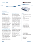
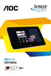
NB5Plus4/W Package Contents
Your NB5Plus4/W Package contains the following items:
•
•
•
The NB5Plus4 or NB5Plus4/W Modem Router (both models shown
above)
•
Telephone Cable (RJ-11)
•
RJ-11 to 605 Adaptor
•
USB Cable
•
CAT-5 UTP Straight Ethernet
Network Cable (RJ-45)
•
Power Adaptor (AC 15V)
Driver and Manual CD
NB5Plus4/W Quick Start Guide
and Package Contents Note
If any of the above items are damaged or missing, please contact your dealer immediately.
NB5Plus4/W User Guide
YML754Rev1
www.netcomm.com.au
Minimum System Requirements
Before continuing with the installation of your NB5Plus4/W, please confirm that you
comply with the minimum system requirements.
•
Pentium® MMX 233MHz
•
A CD-ROM Drive
•
Ethernet card installed with TCP/IP Protocol (required only if you are connecting
to the ETHERNET port of your ADSL Router)
•
USB Port (required only if you are connecting to the USB Port of your ADSL
Router)
•
Host Operating Systems support for USB:
•
•
•
•
Windows®
Windows®
Windows®
Windows®
98 Second Edition
2000
Me
XP (recommended)
•
OS independent for Ethernet
•
Web Browser support:
•
Microsoft Internet Explorer 5.0 (or later versions)
•
Netscape® Navigator 4.0 (or later versions)
•
Most popular browsers
YML754 Rev1
NB5Plus4/W User Guide
www.netcomm.com.au
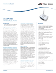
Do I need a Micro filter?
Micro filters are used to prevent common telephone equipment, such as phones,
answering machines and fax machines, from interfering with your ADSL service. If
your ADSL enabled phone line is being used with any other equipment other than
your ADSL Modem then you will need to use one Micro filter for each phone device.
Splitters may be installed when your ADSL line is installed or when your current
phone line is upgraded to ADSL. If your telephone line is already split you will not
need to use a Microfilter - check with your ADSL service provider if you are unsure.
Each micro filter is connected in-line with your telephone or fax machine so that all
signals pass through it. Telephones and/or facsimiles in other rooms that are using
the same extension will also require Microfilters. The following diagram gives an
example of connecting your ADSL Modem/Router using a Microfilter.
NB5Plus4/W User Guide
YML754Rev1
www.netcomm.com.au
LED Indicators
The LED Indicators are located on the front of the unit, they are green in colour,
except the Power LED which is red. The meanings are as follows:
Label
Status
Indicates
Power
On
Power is on.
Off
Power is off.
PPP
Flashing
Trying to authenticate with ISP’s PPP
server.
On
PPP link is up.
Off
No PPP link available.
ADSL
On
A valid ADSL connection.
Flashing
An active WAN session.
On
Wireless link is enabled on NB5Plus4W.
Flashing
Data is being transmitted wirelessly.
WLAN
(NB5Plus4W)
USB
On
PC connected to USB port.
Flashing
Data is being transmitted between NB5Plus4/W and PC.
LAN 4, 3, 2 & 1
Flashing
Flashes when data is being sent or received on the LAN connection.
On
Indicates a link to your LAN or Network
card is active.
Off
Indicates no link to LAN.
YML754 Rev1
www.netcomm.com.au
NB5Plus4/W User Guide
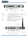
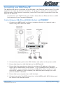
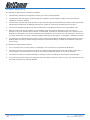
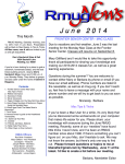
Back Panel Ports
Power jack
for AC power
adaptor
4 x RJ-45
Ports for 10/100
Ethernet LAN
Reset
factory
defaults
USB
Port
RJ11 for ADSL
connection to
telephone line
Rear Panel of the NB5Plus4
Power
Connect the Power Adapt0r that comes with your package.
1, 2, 3, 4
4 x 10/100 Base-T Ethernet jack (RJ-45) to connect to your Ethernet
Network card or Ethernet Hub / Switch.
Reset
To reset your ADSL Router to factory default settings. (All customised settings that you have saved will be lost!)
Please refer to the section below on how to use the
reset function.
USB
USB Port (requires Drivers from accompanying CD).
Line
Telephone jack (RJ-11) to connect to your
Telephone Wall Socket (ADSL line).
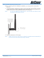
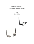
NB5Plus4W
antenna
Power jack
for AC power
adaptor
4 x RJ-45
Ports for 10/100
Ethernet LAN
Reset
factory
defaults
USB
Port
RJ11 for ADSL
connection to
telephone line
Rear Panel of the NB5Plus4W
NB5Plus4/W User Guide
10
YML754Rev1
www.netcomm.com.au
Restoring Factory Defaults
This feature will reset the Modem to its factory default configuration. Occasions may
present themselves where you need to restore the factory defaults on your modem.
Typical situations are:
•
You have lost your username and password and are unable to login to the modem.
•
You have purchased the modem from someone else and need to reconfigure the
device to work with your ISP.
•
You are asked to perform a factory reset by a member of the NetComm Support
staff.
In order to restore your modem to its factory default settings, please follow these
steps:
•
Ensure that your Modem is powered on (for at least 10 seconds).
•
Use a paper clip or a pencil tip to depress the reset button for ten seconds and
release. At this point, the reset is in progress. Do not power off the unit at this
point.
•
When indicator lights return to steady green, reset is complete. The default settings are now restored. The entire process takes about 45 seconds to complete.
•
Once you have reset the modem to its default settings you will be able to access
the device's configuration web interface using http://192.168.1.1 with username
'admin' and password 'admin'.
YML754 Rev1
www.netcomm.com.au
NB5Plus4/W User Guide
11
Default Settings
LAN (Management)
Field
Setting Details
Static IP Address: 192.168.1.1 *
Subnet Mask: 255.255.255.0 *
Default Gateway: blank
WAN (Internet)
Field
Setting Details
User Name:
username@isp
Password:
****
Protocol: PPPoE
VPI: 8*
VCI: 35 *
IP Address: 192.168.1.1 *
Subnet Mask: 255.255.255.0 *
Default Gateway: 0.0.0.0 *
Modem Access
Field
Setting Details
User Name:
admin
Password:
admin
* Default Setting. Although in most cases you will not be required to alter
these default settings for your NB5Plus4/W, your ISP may identify specific
settings to enable connection to their service. Please refer to your ISP or
Network Administrator for further information.
NB5Plus4/W User Guide
12
YML754Rev1
www.netcomm.com.au
Connecting your NB5Plus4/W
The NB5Plus4/W can be connected via a USB cable or an Ethernet cable or both. The USB
connection is simply an ethernet simulation. As far as your computer is concerned the
USB connection is an Ethernet connection, hence DHCP and other protocols will work the
same as for Ethernet.
To connect to your ADSL Router, you need to have either an Ethernet Port or a USB
Port present on your Computer/Notebook.
Connecting your NB5Plus4/W ADSL Modem via ETHERNET
1. Connect your NB5Plus4/W to either a computer directly or a network hub or
switch using CAT5 ethernet cables.
2. Connect the power pack to the ADSL Modem and switch on the power switch.
3. Ensure that there is a LAN link light on the NB5Plus4/W.
4. Ensure that the computer you intend to use has an IP address in the same
subnet as the NB5Plus4/W ADSL Modem. (e.g. the NB5Plus4/W’s default IP is
192.168.1.1 - your computer should be on 192.168.1.100 or similar.) If you
have DHCP enabled on your computer, the NB5Plus4/W will assign your computer a suitable IP address.
5. Ensure that your computer has a LAN link light.
6. Connect one end of the ADSL phone line to the NB5Plus4/W ADSL Modem and
the other end to the wall socket.
YML754 Rev1
www.netcomm.com.au
NB5Plus4/W User Guide
13
Connecting your NB5Plus4/W ADSL Modem via USB
1. Connect the power pack to the NB5Plus4/W ADSL Modem and switch on the
power switch.
2. Connect your NB5Plus4/W to a computer directly via USB cable.
3. When the computer is booted, the Add New Hardware Wizard will launch and
prompt you to provide a driver for your NB5Plus4/W ADSL Modem. Insert the
CD provided.
4. Follow the on-screen prompts to load the driver. Refer to the section below for
more detailed information. (You may need to restart your computer).
5. Connect one end of the ADSL phone line to the NB5Plus4/W ADSL Modem and
the other end to the wall socket.
Installing the USB driver (Windows 98/Me/2000/XP only)
When you install the USB driver on your computer it creates a Virtual Ethernet
Adapter, which can be configured in the same way as a Network Interface card with
DHCP or static IP address. To install the USB driver please follow the steps below:
1. Boot your machine into Windows 98/Me/2000/XP.
2. Insert your NetComm NB5Plus4/W CD into your CD-ROM drive.
3. Plug power up to your NB5Plus4/W and switch ON.
4. Plug a USB cable from the back of the unit into a spare USB socket on your computer.
5. The Windows “Add New Hardware Wizard” should appear. Click Next to continue.
6. Ensure the option “Search for the best driver….” is chosen and click Next.
7. Choose “Specify location”, untick any other boxes and click on the Browse button. Open the CD-ROM drive location of your NetComm NB5Plus4/W CD and
then select the ‘USBdriver’ folder. The USB driver will be installed.
NB5Plus4/W User Guide
14
YML754Rev1
www.netcomm.com.au
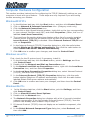
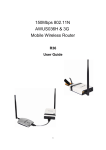
NB5Plus4W Antenna Instructions
Before continuing with the Hardware installation, you may need to connect the
Antenna
1. The antenna has a retaining nut which must be screwed into the SMA connector
on the back of the modem. Place the screw retaining nut over the antenna connection on the rear of the NB5Plus4W and turn it clockwise.
Note:
Do not over-tighten the attaching nut - but do make sure that you have
screwed it all the way to its end.
Screw retaining
nut clockwise
over the antenna
connection
Bend antenna
to a 90o angle
2. Bend the antenna to a 90o angle.
Note:
Please note that you may have to rotate the complete antenna assembly to
do this and have the antenna pointing vertically.
YML754 Rev1
www.netcomm.com.au
NB5Plus4/W User Guide
15
Configuring your NB5Plus4/W
You will need to log directly into the configuration page of the modem and configure
the basic settings for your Internet connection. Your ISP should provide you with the
necessary information to complete this step.
The settings that you most likely need to change to access the Internet are grouped onto
a single EasyConfig page.
To configure your modem follow the steps below:
Note:
Ensure that your PC is setup as a DHCP client. Refer to the Computer
Hardware Configuration section for instructions on how to set this up with
different Operating Systems.
1. Insert the CD into your CD-ROM drive. An autorun screen will appear. Click on
Configure Modem.
(Alternatively, if the CD-ROM is not available, you can open a web
browser and type http://192.168.1.1 in the location bar to access the
modem’s EasyConfig setup screen directly.)
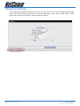
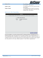
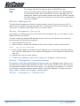
2. The login page will be displayed. Enter the modem’s username and password.
The default username is admin.
The default password is admin.
Click on Log In.
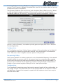
3. The EasyConfig page will be displayed.
NB5Plus4/W User Guide
16
YML754Rev1
www.netcomm.com.au
4. Check with your ISP what Protocol your modem needs to use to connect to the
Internet. If unsure, leave the default selection of PPPoE.
5. In the User ID field, enter the Username that your ISP has provided. In the
password field, enter the password that your ISP has given you.
Note:
If your ISP has provided you with Static addressing details you will need
to access the Advanced Settings of your modem to configure these. Please
refer to the section on Advanced Settings in this manual for instructions.
6. The default VPI / VCI settings for most connections is 8 / 35 in Australia. Do not
change these unless your ISP has instructed you to do so.
7. Click on the Apply button to save the settings you have entered. The modem will
automatically reboot. Refresh the web page after 20 seconds.
8. If the settings you entered were correct and you have an ADSL connection established the Status light will change to green.
9. You should now be able to access the Internet with a web browser, email client
or other Internet application.
10.If the status light remains red after 45 seconds and you have refreshed your
web page several times, check the following:
• ADSL Link light on your modem is solid green; If not, you do not have a
connection established with your local DSLAM. Please call your ISP who will
assist in resolving this.
• If you have a solid green light on your modem for the ADSL Link, check that
the username / password you entered are correct and try again;
• If the above two suggestions don’t resolve the issue, please contact your ISP;
TIP: To test your Internet connection while the modem is attempting to apply
the settings, you can open a DOS prompt (Start > Run > cmd) and execute
a continual ping command to a public server’s IP address on the Internet.
Once you receive a reply from the server you know that you are connected.
This can take up to 30 seconds. e.g: c:/ ping 210.0.111.111 -t
YML754 Rev1
www.netcomm.com.au
NB5Plus4/W User Guide
17
Computer Hardware Configuration
This section provides instructions for configuring the TCP/IP (Network) settings on your
computer to work with your Modem. These steps are only required if you are having
trouble accessing your Modem.
Windows® XP PCs
1.
2.
3.
4.
In the Windows task bar, click the Start button, and then click Control Panel.
Click on Network & Internet Connections icon. (Category mode only).
Click the Network Connections icon.
In the LAN or High-Speed Internet window, right-click on the icon corresponding
to your network interface card (NIC) and select Properties. (Often, this icon is
labelled Local Area Connection).
5. The Local Area Connection dialog box displays with a list of currently installed
network items. Ensure that the check box to the left of the item labelled Internet Protocol (TCP/IP) is checked. Select Internet Protocol TCP/IP and
click on Properties.
6. In the Internet Protocol (TCP/IP) Properties dialog box, click the radio button
labelled Obtain an IP address automatically. Also click the radio button labelled Obtain DNS server address automatically.
7. Click OK twice to confirm your changes, and close the Control Panel.
Windows 2000 PCs
First, check for the IP protocol and, if necessary, install it:
1. In the Windows task bar, click the Start button, point to Settings, and then
click Control Panel.
2. Double-click the Network and Dial-up Connections icon.
3. In the Network and Dial-up Connections window, right-click the Local Area
Connection icon, and then select Properties.
4. In the Local Area Connection Properties dialog box, select Internet Protocol
(TCP/IP), and then click Properties
5. In the Internet Protocol (TCP/IP) Properties dialog box, click the radio
button labelled Obtain an IP address automatically. Also click the radio button
labelled Obtain DNS server address automatically.
6. Click OK twice to confirm and save your changes, and then close the Control
Panel.
Windows Me PCs
1. In the Windows task bar, click the Start button, point to Settings, and then
click Control Panel.
2. Click on View All Control Panel Options.
3. Double-click the Network icon.
4. The Network Properties dialog box displays with a list of currently installed
network components. If the list includes Internet Protocol (TCP/IP), then the
protocol has already been enabled. Skip to step 10.
5. If Internet Protocol (TCP/IP) does not display as an installed component, click
Add…
6. In the Select Network Component Type dialog box, select Protocol, and
then click Add…
NB5Plus4/W User Guide
18
YML754Rev1
www.netcomm.com.au
7. Select Microsoft in the Manufacturers box.
8. Select Internet Protocol (TCP/IP) in the Network Protocols list, and then click
OK. You may be prompted to install files from your Windows ME installation CD
or other media. Follow the instructions to install the files. If prompted, click OK
to restart your computer with the new settings.
Next, configure the PC to accept IP information assigned by the modem:
9. Follow steps 1 – 4 above..
10.In the Network Properties dialog box, select TCP/IP, and then click Properties.
If you have multiple TCP/IP listings, select the listing associated with your network card or adapter.
11.In the TCP/IP Settings dialog box, click the radio button labelled Obtain an
IP address automatically.
12.Click OK twice to confirm and save your changes, and then close the Control
Panel.
Windows 95, 98 PCs
First, check for the IP protocol and, if necessary, install it:
1. In the Windows task bar, click the Start button, point to Settings, and then
click Control Panel.
2. Double-click the Network icon.
3. The Network dialog box displays with a list of currently installed network
components. If the list includes TCP/IP, and then the protocol has already been
enabled. Skip to step 9.
4. If TCP/IP does not display as an installed component, click Add… The Select
Network Component Type dialog box displays.
5. Select Protocol, and then click Add… The Select Network Protocol dialog box
displays.
6. Click on Microsoft in the Manufacturers list box, and then click TCP/IP in the
Network Protocols list box.
7. Click OK to return to the Network dialog box, and then click OK again. You
may be prompted to install files from your Windows 95/98 installation CD. Follow
the instructions to install the files.
8. Click OK to restart the PC and complete the TCP/IP installation.
Next, configure the PCs to accept IP information assigned by the Modem:
9. Follow steps 1 – 3 above.
10.Select the network component labelled TCP/IP, and then click Properties. If
you have multiple TCP/IP listings, select the listing associated with your network
card or adapter.
11.In the TCP/IP Properties dialog box, click the IP Address tab.
12.Click the radio button labelled Obtain an IP address automatically.
13.Click OK twice to confirm and save your changes. You will be prompted to restart Windows.
14.Click Yes.
Note:
For detailed information regarding the advanced features of this product, please refer to the configuring sections in the NB5Plus4/W User
Guide on the supplied CD-ROM.
YML754 Rev1
www.netcomm.com.au
NB5Plus4/W User Guide
19
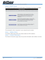
Advanced Settings
To access the Advanced Settings of your modem you click on the Advanced Settings
link on the EasyConfig web page. To access this page, enter http://192.168.1.1 and
login with username ‘admin’ and password ‘admin’.
NB5Plus4/W User Guide
20
YML754Rev1
www.netcomm.com.au
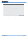
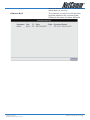
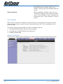
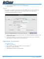
Setup
Click the Setup tab.
The Setup screen allows you to change current settings for your LAN (Local Area
Network), Ethernet Switch and WAN (Wide Area Network). You can also create new
connection profiles.
YML754 Rev1
NB5Plus4/W User Guide
www.netcomm.com.au21
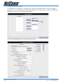
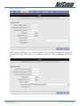
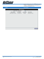
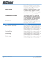
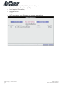
Setup>LAN Configuration
Click on the LAN Configuration link under the Setup menu to configure your Local
Area Network settings.
Interfaces
This section displays the available interfaces on your modem that have yet to be
configured. The default setting is to have all interfaces in LAN group 1.
It is possible to have separate LAN groups:
• three if you have the NB5Plus4W:
i) USB;
ii) Ethernet;
iii) WLAN (Wireless LAN);
• two if you have the NB5Plus4:
i) USB;
ii) Ethernet;
LAN Groups
Configuring LAN Groups with static IP addresses must be done in such a way that
the range of assignable IP addresses in each of the LAN groups should not overlap
with other LAN groups. A rule of thumb would be that each LAN group should be
on its own network or subnet. For example, say you have 3 LAN groups each being
setup with static IP addressing. Below is a sample configuration:
LanGroup #1
IP Address 192.168.1.1
NetMask 255.255.255.0
LanGroup #2
IP Address 192.168.2.1
NetMask 255.255.255.0
NB5Plus4/W User Guide
22
YML754Rev1
www.netcomm.com.au
LanGroup #3
IP Address 192.168.3.1
NetMask 255.255.255.0
The above example shows that each LAN group is on its own network and that there
is no overlap in assignable IP address based on netmask.
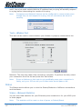
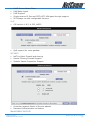
To remove an interface from LAN group 1, click on the interface (e.g. USB) and click
the Remove button:
To add the available interface from the Interfaces section to a LAN group, highlight
the interface and click the Add button of the appropriate LAN group. To add the
available USB interface to LAN group 2 highlight the USB interface in the Interfaces
section and click the Add button for LAN group 2:
YML754 Rev1
NB5Plus4/W User Guide
www.netcomm.com.au23
Configuring LAN Groups
To configure an interface of a LAN group click the interface and click the Configure
hyperlink. E.g. to configure the Ethernet interface for LAN group 1 click the Ethernet
interface and click the Configure hyperlink:
You will be presented with the following screen:
NB5Plus4/W User Guide
24
YML754Rev1
www.netcomm.com.au
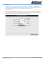
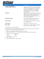
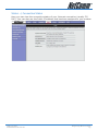
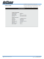
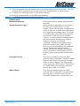
IP Settings
The IP address is usually 192.168.1.1 but you can change it to another suitable
number (e.g. 192.168.0.1 or 10.0.0.1 or 172.16.1.1) to suit any existing network
devices you already have installed. The NetMask describes how big your network is,
the default 255.255.255.0 will allow for 253 computers and generally does not need
to be changed unless to suit existing network requirements.
Note: If you change your IP address the DHCP server in your modem will automatically change the IP address range (DHCP pool) it hands out accordingly.
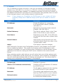
Option
Description
IP Address: Private IP address for connecting
to a local private network (Default:
192.168.1.1).
Netmask: Netmask for the local private network
(Default: 255.255.255.0).
Default Gateway: This field is optional. Enter in the IP address of the router on your network.
Host Name: Required by some ISPs. If the ISP does
not provide the Host name, please leave
it blank.
Domain Name: www.dyndns.org will provide you with
a Domain Name. Enter this name in the
“Domain Name” field.
Apply: Click Apply to save the changes.
DHCP stands for Dynamic Host Configuration Protocol. Your Modem has its DHCP
Server enabled by default. This means it will assign valid IP addresses to each
computer connected to it and will direct those computers to use the Modem as the
gateway to the Internet. Having the DHCP server enabled is the recommended
choice.
When selecting certain radio buttons you will notice that some of the options available for configuration will be greyed out. For example, when selecting ‘Unmanaged’
you will notice that all fields under IP Settings are greyed out. This means that no
settings are configurable if the interface is unmanaged.
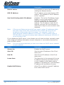
Option
Description
Unmanaged
Interface is ignored.
Obtain an IP Address automatically
Interface will be allocated an IP address
by a DHCP server.
IP Address
The IP address assigned to the interface
by a DHCP server on your network.
Netmask:
The subnet mask assigned to the interface by a DHCP server on your network.
Release button
It is possible to release the IP address
by clicking the Release button.
YML754 Rev1
NB5Plus4/W User Guide
www.netcomm.com.au25
Option
Description
Renew button
It is possible to renew the IP address by
clicking the Release button.
PPP IP Address
The IP address to be used during a PPP
session. This defaults to the IP address
of the interface.
Use the following static IP address (Default) This is the IP address of your
Modem on your local network. This IP
address is specified on all computers
on your network as the Gateway IP
address. The IP address is also the IP
address you type into your browser location bar to login to your modem’s web
interface.
Note: If Server and Relay are turned off you need to assign IP addresses within
the same range to the PCs connected to the modem else they will not
be able to communicate with the modem. For example, if your modem’s Ethernet interface address is 192.168.1.1 with a subnet mask of
255.255.255.0 you need to assign static addresses starting at 192.168.1.2
up to 192.168.1.253.
If you disable the DHCP server in the Modem you will need to either manually (statically) assign IP address information to each computer or use another device/computer as DHCP server.
Note: It is not recommended that you have more than one DHCP server enabled
on your network.
Option
Description
Server On: Enables the DHCP server.
Start IP: Sets the start IP address of the IP address pool.
End IP: Sets the end IP address of the IP address pool.
Lease time: The lease time is the amount of time an
IP address issued by the DHCP service
of your modem is valid before being
updated. If all fields are 0, the allocated
IP address will be effective forever.
Enable DHCP Relay: Allow PCs on LAN to request IP address
from other DHCP server.
NB5Plus4/W User Guide
26
YML754Rev1
www.netcomm.com.au
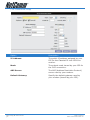
Services
It is possible to set the services for an interface by clicking on the hyperlink which
will take you to the page to configure them. Please refer to the relevant section in
this manual for information on the settings for these services.
Ethernet Switch
The 4-port Ethernet switch of your modem is set to automatically adapt to the type
of connection plugged into a specific port. To force a port to connect at a specific
speed, select the setting from the dropdown menu of a port.
YML754 Rev1
NB5Plus4/W User Guide
www.netcomm.com.au27
WAN Setup>New Connection
If you click ‘New Connection’ you will see the screen shown below.
The Connection setup page requires you to choose the correct settings to work with
your ADSL connection as specified by your ISP. The screen will add or remove nonapplicable choices as you change options. There are a few main settings you will
need to confirm with your ISP before you can complete this page, these are;
•
Type of Connection (e.g. PPPoE, PPPoA, Static, DHCP, Bridge, CLIP)
•
Username & Password (usually only required for PPPoE or PPPoA types)
•
VPI & VCI (usually VPI=8 and VPI =35)
•
Authentication (Usually AUTO will work otherwise check with your ISP)
Most other choices on this screen are personal preference and not critical to getting
your connection working.
Note: The Username & Password you need to type in here is for your ISP’s account and it will be supplied to you by your ISP.
PPPoE Connection Setup Fields
Option
Description
Name
You need to provide for a connection
(e.g. MyISP)
Type
Select the type of connection for this
profile.
Sharing
Decide whether you want to share this
connection. You can share a connection
using a VLAN (Virtual LAN) or by a PVC
(Private Virtual Circuit).
NB5Plus4/W User Guide
28
YML754Rev1
www.netcomm.com.au
Option
Description
Options:
NAT (Network Address Translation allows you to share the public IP address assigned to the WAN (Wide Area
Network) interface of your modem with
multiple clients on your LAN (Local
Area Network). NAT also acts as a basic
firewall. The firewall feature protects the
PCs on your LAN from malicious attacks
from people on the Internet (e.g. DOS
attacks).
NAT / Firewall
VLAN ID
If you decide to share this connection
with a VLAN, this field will be enabled
and you need to select your VLAN ID.
For example, if you have your Ethernet
interface in LAN Group 1 and your USB
interface in LAN Group 2 you can create
a VLAN for both groups to access each
other. 1
Priority Bits
Set the priority bit of the Ethernet frame
if using a VLAN.
1
For more information on VLANs visit http://www.javvin.com/protocol/VLAN.html.
YML754 Rev1
NB5Plus4/W User Guide
www.netcomm.com.au29
PPPoE Connection Setup
PPP Settings
Option
Description
Username: Enter the username provided by your
ISP.
Password: Enter the password provided by your
ISP.
Idle Timeout: Idle timeout means the router will
disconnect after being idle for a preset
amount of time. The default is 60 seconds. If you set the time to 0, the ADSL
connection will remain always connected
to the ISP.
Keep Alive: If mode is LCP, This is the Keep Alive
timer. If a reply to the LCP echo is not
received in this amount if time, the connection is dropped. The Default is 10.
Authentication: Default is Auto. However, if your ISP
asks you to specify the authentication
type, you can select it here (CHAP or
PAP).
MTU
Maximum Transmission Unit indicates
the largest packet size in bytes that the
modem transmits. Any packets larger
than the MTU setting are fragmented
into smaller packets before being transmitted.
NB5Plus4/W User Guide
30
YML754Rev1
www.netcomm.com.au
Option
Description
On Demand: If enabled the Idle Timeout field can be
modified. On Demand specifies that the
modem will connect to the Internet on
demand.
Default Gateway: Specifies that this connection will be the
default gateway for other LAN groups to
access the Internet.
Enforce MTU: Specifies that the MTU setting will be
enforced.
Debug: Enable to turn on the debugging mode
of your modem. Your ISP may ask you
to do this should you be experiencing
problems connecting to the Internet.
PPP Unnumbered: An unnumbered interface does not have
an IP address assigned to it. An unnumbered interface is often used in point-topoint connections where an IP address
is not required. You’ll notice that once
PPP Unnumbered is enabled you need
to choose the LAN group to which this
applies.
YML754 Rev1
NB5Plus4/W User Guide
www.netcomm.com.au31
PVC (Private Virtual Circuit) Settings
Option
Description
VPI: (Virtual Path Identifier) If instructed
to change this, type in the VPI value
for the initial connection (using PVC 0).
Default = 0.
VCI: (Virtual Channel Identifier) If instructed
to change this, type in the VCI value
for the initial connection (using PVC 0).
Default = 0.
Your modem can support up to 8 PVCs.
For example, you could have one PVC
(8/35) for your Internet traffic, and
another PVC (9/35) for your VoIP traffic.
Contact your ISP for further details.
QoS: Default is UBR (Unspecified Bit Rate).
Change this setting if your ISP instructs
you to do so. The other settings are CBR
(Constant Bit Rate) and VBR (Variable
Bit Rate).
PCR: Divide the DSL line rate (bps) by 424
(the size of an ATM cell) to find the Peak
Cell Rate (PCR). This is the maximum
rate at which the sender can send cells.
SCR: The Sustain Cell Rate (SCR) sets the
average cell rate (long-term) that can
be transmitted.
MBS: Maximum Burst Rate. Represents the
maximum number of cells accepted
over a period of time. When the cell rate
exceeds the MBS cells can be dropped.
CDVT: Cell Delay Variation Tolerance. If your
PVC is a CBR service you need to set
the PCR and CDVT parameters. Ask your
ISP what the best settings are for these
on their network.
Auto PVC: If enabled your modem will automatically detect your PVC (VPI/VCI) settings.
Connect /
Disconnect Buttons: Click Connect button to attempt to connect using the settings you have specified. Click Disconnect button to disconnect the current profile.
Apply: Click Apply to save the changes.
NB5Plus4/W User Guide
32
YML754Rev1
www.netcomm.com.au
PPPoA Connection Setup
When specifying your connection Type to be PPPoA you are able to change the Encapsulation to either LLC (Logical Link Control) or VC (Virtual Circuit) encapsulation.
The default is LLC so do not change this setting unless your ISP instructs you to do
so.
YML754 Rev1
NB5Plus4/W User Guide
www.netcomm.com.au33
Static Connection Setup
Option
Description
Encapsulation: Select the method of encapsulation used
by your ISP. The default is LLC, so only
change this to VC if your ISP asks you
to.
IP Address: If your ISP has issued you with a static
public IP address, you need to specify it
here. (e.g. 210.1.123.123).
Mask: The subnet mask specified by your ISP.
Default Gateway: The default gateway specified by your
ISP.
DNS: You have the choice to specify up to
three DNS (Domain Name Service)
servers. The function of a DNS server
is to map URL names (e.g. www.
google.com.au) to their IP addresses
(e.g.66.102.7.147). If DNS 1 is down,
your modem will use DNS 2.
Mode: Bridged and Routed
NB5Plus4/W User Guide
34
YML754Rev1
www.netcomm.com.au
DHCP Connection Setup
Option
Description
Encapsulation: Select the method of encapsulation
used by your ISP from the drop-down
list box. Choices vary depending on the
mode you select in the Mode field.
IP Address: The IP address assigned by an external
DHCP server.
Mask: The subnet mask assigned by an external DHCP server.
Gateway: The gateway assigned by your DHCP
server.
Default Gateway: Enable this if you want to use this profile connection as the default gateway
for clients to connect to the Internet.
Bridge Settings
Encapsulation: Select the method of encapsulation
used by your ISP from the drop-down
list box. Choices vary depending on the
mode you select in the Mode field.
Select LAN: Select the LAN group to which you want
to bridge this connection to. Having a
Bridged Connection places the modem
into a ‘dumb’ mode. The modem connects to the ISP, but does not perform
authentication, routing or firewalling
functions. You will need to have an additional router plugged into a LAN port of
your modem to perform these functions.
YML754 Rev1
NB5Plus4/W User Guide
www.netcomm.com.au35
CLIP Connection Setup
Option
Description
IP Address: The public IP address assigned by your
ISP for the Classical IP over ATM connection.
Mask: The subnet mask issued by your ISP for
the CLIP connection.
ARP Server: The ARP (Address Resolution Protocol)
server used by your modem.
Default Gateway: Specify the default gateway used by
your modem (issued by your ISP).
NB5Plus4/W User Guide
36
YML754Rev1
www.netcomm.com.au
WAN Setup>Modem
Here you can choose one of four ADSL handshake types, typically MMode (Multimode) will work on Australian ADSL lines. You should not need to change this setting unless advised by your ISP.
Option
Description
T1413: Full-Rate (ANSI T1.413 Issue 2) with
line rate support of up to 8 Mbps downstream and 832 Kbps upstream.
GDMT: Full-Rate (G.dmt, G992.1) with line rate
support of up to 8 Mbps downstream
and 832 Kbps upstream.
GLITE: G.lite (G.992.2) with line rate support
of up to 1.5 Mbps downstream and 512
Kbps upstream.
MMODE: Support Multi-Mode standard (ANSI
T1.413 Issue 2; G.dmt(G.992.1);
G.lite(G.992.2)).
Click Apply to save the changes.
YML754 Rev1
NB5Plus4/W User Guide
www.netcomm.com.au37
Logout
Click Log Out to logout of the modem’s configuration interface.
NB5Plus4/W User Guide
38
YML754Rev1
www.netcomm.com.au
Advanced
The Advanced menu allows you to configure a number of features of your modem.
This section deals with these features.
YML754 Rev1
NB5Plus4/W User Guide
www.netcomm.com.au39
Advanced>UPnP
Your modem is Universal Plug ‘n Play Capable, for security this feature is disabled by
default. UPnP is a method of allowing devices and computer software on your Network to be able to configure ‘unblocked’ ports through your modem (and through
your modem’s firewall). This makes it easier to run Network games and Programs
like Microsoft Messenger etc.
To Enable UPnP click the Enable UPnP box and choose the WAN connection (usually
‘PPPoE’). Select the LAN Connection (e.g. LAN Group 1) to which UPnP is to be applied to.
Option
Description
Enable UPNP: Enable the UPnP.
Click Apply to save the changes.
2
For more information on Universal Plug and Play, see http://www.microsoft.com/
technet/prodtechnol/winxppro/evaluate/upnpxp.mspx.
NB5Plus4/W User Guide
40
YML754Rev1
www.netcomm.com.au
Advanced>SNTP
SNTP (Simple Network Time Protocol) allows your modem to update its time automatically using an SNTP server. To enable this feature, click the Enable SNTP tick
box.
YML754 Rev1
www.netcomm.com.au
NB5Plus4/W User Guide
41
Option
Primary, Secondary,
Tertiary SNTP Servers Description
This allows you to enter three different
SNTP server addresses. If one of these
servers is unavailable your modem
will use an alternative. An example
of an NTP server on the Internet is
128.250.36.3.
Timeout: The number of seconds your modem will
attempt to connect to an SNTP server
before trying an alternative server
should the server you are trying to connect to be unavailable.
Polling Interval: The interval that your modem will update its time with an SNTP server.
Retry Count: The number of attempts at connecting
to an SNTP server.
Time Zone: Select the time zone you are in.
Day Light: Enable this to enable daylight savings
for the time on your modem.
Click Apply to save the settings.
To check that your NB5Plus4/W modem is talking to an NTP server, follow these
instructions for Windows Operating Systems:
1. Open a Command Prompt (Start > Run > cmd).
2. Type telnet 192.168.1.1 (or the IP address of your modem) and enter.
3. Type your login and password.
Login: admin
Password: admin
4. date [ENTER key]
5. Note that the date is set correctly.
NB5Plus4/W User Guide
42
YML754Rev1
www.netcomm.com.au
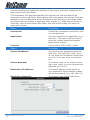
Advanced>IPQoS
IP QoS (Quality of Service) allows you to set priorities for traffic travelling through
your modem. For example, you may want to prioritize your UDP traffic over your
TCP traffic. Typical UDP traffic would be your VoIP (Voice over Internet Protocol)
traffic. This section describes how to make use of your modem’s IPQoS feature.
The NB5Plus4/W should have two primary sections for setting up IP QoS services:
1. A QoS setup page to configure the upstream/downstream connection queue
priorities, and
2. A Rules configuration page.
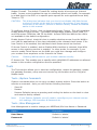
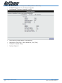
QoS Setup Page
The QoS setup page will have 2 primary fields:
1. Connection name selection,
2. A table to select queue weights for the system transmit queues.
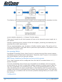
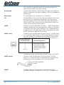
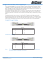
IP QoS traffic shaping is associated with any transmitted traffic from the perspective
of the NB5Plus4/W. Each interface has 3 priority queues associated with transmit
data. The web UI will allow the user to choose any interface connection and select
the priority weights associated with that connection. For Example; the user could
have a connection named WAN1 or a connection named LAN1. If the user selects
WAN1 the transmit queues will be associated with that connection, and likewise
with LAN1 (Refer to the following diagrams). All interfaces on the LAN are currently
bridged and therefore the only connection name is that name associated with the
LAN.
Transmit queues associated with WAN connection
Transmit queues associated with LAN connection
The high priority queue has strict priority over the medium and low priority queue,
and therefore can exhaust all available bandwidth. The web UI will allow the user to
select the weights of the medium and low priority queues in increments of 10 percent so that the sum of the weights of the 2 queues is equal to 100 percent. These
queues will be serviced on a Round Robin priority basis according to the weights
assigned, after the high priority queue has been completely serviced.
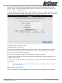
Rules Configuration Page
The Rules configuration page will allow the user to define IP matching fields to associate with the priority queues associated with the named connections selected above
in the “QoS Setup Page” section.
There will be three primary fields for the user to select: 1.) A Trusted mode check
box. 2.) A traffic priority choice (High, Medium, Low), and 3.) An IP rules matching
selection area.
The NB5Plus4/W has two primary modes of operation with regard to queue traffic
prioritization; Trusted, and Un-trusted. The Web UI will provide one check box to
enable trusted mode. In trusted mode all rules will be applied first regardless of the
setting of the TOS bits. After the rules have been exhausted the existing TOS bit
settings will be honoured. If the “Trusted mode” box is unchecked this will indicate
the “Un-trusted mode.” “Un-trusted” mode will match first against all rules as in
“Trusted” mode. The difference is that if there is no match then a default rule will be
used. The default rule will have an associated queuing priority.
YML754 Rev1
www.netcomm.com.au
NB5Plus4/W User Guide
43
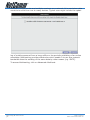
Rule definitions will be defined by the user by allowing the user to select matching
based on Source IP, Destination IP, IP Protocol, Source Port, Destination Port, and
Incoming Mac Port (switched LAN Port). These selections will define a rule and be
associated with a particular queue priority: High, Medium, and Low.
Traffic Queuing Configuration
Based on the TOS (DSCP) marking, the NB5Plus4/W shall prioritize the traffic servicing on the outgoing interface (facing the Access Network) using a 3-band priority
mechanism as described below.
Queue Priorities:
NB5Plus4/W User Guide
44
YML754Rev1
www.netcomm.com.au
One Expedited Forwarding (EF) Queue: High Priority queue with non-preemptible
service. The EF queue is always scheduled first prior to the medium and low priority
queues and runs to completion
Two Queues (Medium and Low Priority) with Weighted Round Robin service. Based
on the associated weights, packets on these queues share the remaining link
bandwidth (after the EF service). The low priority queue corresponds to Best Effort
service. Looking forward, the medium priority queue will play the role of Assured
Forwarding Queue.
Configuration:
a.) The Medium, and Low Priority Queue weights will be selectable via the Web UI.
User weights for these two queues are entered as a percentage in increments of
10%. The sum of the 2 weights must be equal to 100 percent.
En-queuing Policy
Inter-queue isolation to make greed work on the Residential Gateway: the transmit
interface buffer (a common pool for all queues) can be monopolized by a greedy
flow on the low priority queue thus preventing en-queuing high priority traffic. To
prevent such conditions the en-queuing process is using a simple configurable allocation of per-queue lengths, adding up to the total queue length.
Configuration:
The Expedited Forwarding queue (fast service queue) length will be configurable via
the config.xml file. This parameter will not be configurable via the Web UI. Please
call NetComm Support and request to speak with an engineer should you require
this XML file to edit.
YML754 Rev1
www.netcomm.com.au
NB5Plus4/W User Guide
45
The Medium and Low priority queue lengths will be proportionally calculated via the
queue weights selected in 1.) Queue Priorities above.
Total queue length for all three queues will sum to the transmit queue length set in
the system.
Packets overflowing their queues will be tail-dropped, penalizing stochastically the
greediest flow within each queue.
Future implementations may introduce a “buffer stealing” policy. This policy will remove the fixed buffer limits and allow a particular queue buffer to decrease to some
predefined minimum limit.
De-queuing Policy
Expedited Forwarding Queue (High Priority) is always serviced first at each packet
scheduling cycle and serviced to extinction. Therefore, the EF queue is non-preemtible by the Medium and Low priority queues.
WRR Queue Scheduler for Medium and Low priority queues
The L and M weights will be configured from the Web UI as stated above in 1.)
Queue Priorities.
A service scheduling array will be pre-computed for the Medium and Low priority
queues based on the user configurable weights assigned to these queues. Each array slot corresponds to a scheduling cycle. The pre-computed algorithm will allocate scheduling slots for each queue based on the Medium and Low priority queue
weights and uniformly interleave them through the scheduling array. This array will
provide an O(1) scheduler with a minimum possible average latency for each of the
two queues.
Configuration:
NB5Plus4/W User Guide
46
YML754Rev1
www.netcomm.com.au
The weighted values used for the WRR scheduler will be calculated based on the
percentage weights the user inputs in the Web UI as stated above in 1.) Queue
Priorities.
Example: User selects a Medium Queue Weight = 60 %, and Low Queue Weight =
40%. Then the O(1) scheduling array will look like {L, M, M, L, M, M, L, M, M, L}
where L and M represents a scheduling cycle for the respective Low and Medium
queues.
Low Latency Queue (Fragmentation and Interleaving) for Voice Traffic
With Voice traffic shared over same PVC with Data traffic, the simple packet classification and prioritization will not suffice to achieve the low latency required by voice.
In this case, a voice call triggers dynamic flushing of existing data packets from
device queues (including DSL device driver) for Head of Line Blocking removal, and
IP MTU resizing based on uplink bandwidth for fragmentation and packet interleaving of voice and data. Below is an example of MTU calculations:
Total delay PSTN delay
end-to-end budget
VIF
(ms)
(ms)
100kbps
10ms
200
100
207
20ms
200
100
82
30ms
200
100
x
Maximum Data Fragment size
based on upstream bandwidth (bytes)
150kbps
200kbps
250kbps
363
519
675
175
269
363
x
19
50
For Voice traffic priority an extra EF queue was added to PRIOWRR. This extra
queue should not be exposed via WebUI config for data usage. Its use is triggered
internally by the voice app using the socket options system calls. Voice packets are
using this EF queue. Signalling for Voice uses the next EF queue that’s also exposed
on the web config. This means that voice signalling can be mixed with data if user
configures data for High Priority.
TOS-to-Priority Mapping
High Priority Marking for Expedited Forwarding Queue: DSCP Mark: xx1000
Medium Priority Marking: DSCP Mark: xx0100
Low Priority Marking for Best Effort: DSCP Mark: xx0000
The four TOS bits (the ‘TOS field’) are defined as:
Binary Meaning
1000 Minimize delay (md)
0100 Maximize throughput (mt)
0010 Maximize reliability (mr)
0001 Minimize monetary cost (mmc)
0000 Normal Service
TOS
Bits
Means
Linux Priority
Queue Priority Band
0x0
0
Normal Service 0
Best Effort 2
0x2 1
Minimize Monetary Cost 1 Filler 2
YML754 Rev1
www.netcomm.com.au
NB5Plus4/W User Guide
47
0x4 2
Maximize Reliability 0
Best Effort 2
0x6 3
mmc+mr 0
Best Effort 2
0x8 4
Maximize Throughput 2
Bulk 1
0xa 5
mmc+mt 2
Bulk 1
0xc 6
mr+mt 2
Bulk 1
0xe 7
mmc+mr+mt 2
Bulk 1
0x10 8
Minimize Delay 6
Interactive 0
0x12 9
mmc+md 6
Interactive 0
0x14 10 mr+md 6
Interactive 0
0x16 11 mmc+mr+md 6
Interactive 0
0x18 12 mt+md 4
Int. Bulk 1
0x1a 13 mmc+mt+md 4
Int. Bulk 1
0x1c 14 mr+mt+md 4
Int. Bulk 1
0x1e 15 mmc+mr+mt+md 4
Int. Bulk 1
The Default queue priority for non-mapped TOS values is Best Effort.
Advanced>LAN Clients
LAN Client names are a way of applying specific Port-forwarding and Access Control rules to individual computers on the LAN. If DHCP is used, all DHCP clients are
automatically assigned and are designated as a LAN client.
To add a LAN client, click Advanced>LAN Clients.
Option
Description
Select LAN Group: Select the LAN group you would like to
add a LAN client to.
Enter IP Address:
Enter the IP address of the LAN client to
be added.
Hostname: Enter the Hostname.
MAC Address: Enter the MAC address of the new client. To find out the MAC address of the
client, open a command prompt and
execute an ipconfig/all command (Windows 2000/XP). Note, it is optional to
add the MAC address of the device. The
format to add the MAC address is xx:xx:
xx:xx:xx:xx.
Apply: Click Apply to save the changes.
Advanced > LAN Isolation
NB5Plus4/W User Guide
48
YML754Rev1
www.netcomm.com.au
You are able to restrict communication between clients in different LAN groups. If
you have the NB5Plus4 you can restrict traffic between two LAN groups. If you have
the NB5Plus4W you can restrict traffic between three LAN groups (Ethernet, USB,
Wireless).
Advanced > Bridge Filters
Bridge filtering enables rules to be defined which allow or deny data to pass through
the Router based on the source and destination Bridge address and data type of
each data frame.
To access Bridge Filters Control, click on Advanced>Bridge Filters.
Usage examples of Bridge Filter Rules are: to specify which computers on a network
are allowed Internet access; or to determine which particular computers are allowed
to access services provided by the Router (the last point is particularly relevant for
routers serving Wireless Networks as it can be used to prevent unauthorised people
from attaching themselves to a wireless LAN).
Enable/Disable Bridge Filtering
To enable Bridge filtering, navigate to the Bridge Filter Control Screen and select the
Enable Bridge Filters check box.
If the check box is selected, Bridge filtering is enabled according to the list of Bridge
Filter Rules that has been created.
If the box is de-selected, Bridge Filtering will not be enabled, even if Bridge Filter
Rules have been created.
Create Bridge Filter Rules
Enter the Source Bridge and Destination Bridge details. Entering zeros or blanks
into the Source or Destination fields enters a null value.
‘Protocol’ provides the choice of protocol type for the rule.
‘Mode’ provides the choice of Allow or Deny for the rule.
When all selections are made, click on Add to add the rule to the list of rules. A
maximum of 20 Bridge Filter Rules can be defined and saved.
To save changes, click on Apply.
Edit or Delete Bridge Filter Rules
YML754 Rev1
www.netcomm.com.au
NB5Plus4/W User Guide
49
Option
Description
WAN Connection: Refers to the active Connection Profile.
Allow Incoming Ping: Enabling this feature allows users on
the WAN side of your modem to receive
replies to an ICMP ping command. Useful for testing remote connection to your
modem.
Select LAN Group: Select the LAN group for which you are
setting up the port forwarding rules for.
LAN IP: Select the device (PC) to which you will
be port forwarding data to. The default
will be the LAN device currently logged
in to the modem’s web interface. For
example, if you had a web server with
IP address 192.168.1.100, you would
select this from the drop-down list.
New IP: If you wish to manually add a LAN client
so that you can apply rules to it, click
on the New IP Button and enter Host
Name, MAC Address and IP Address.
Note: The MAC address needs to be
entered in the format xx:xx:xx:xx:xx:
xx. You do not need to enter a MAC address.
DMZ Settings
A DMZ (demilitarized zone) is a computer host or small network inserted as ‘neutral
territory’ between a private LAN and the Internet. It prevents outside users from
NB5Plus4/W User Guide
50
YML754Rev1
www.netcomm.com.au
getting direct access to LAN computers while still being able to access services
hosted on the designated DMZ Computer.
When using NAPT to share your internet connection, LAN computers will still be able
to access the Internet when the DMZ host is enabled. Any direct communication
to the WAN port of your Modem that is not a reply to the original NAPT request is
forwarded to the DMZ host.
Option
Description
Select your WAN
Connection: Select the connection to which your
DMZ client is connected to.
Select LAN group: Select the LAN group in which you want
to place the DMZ client.
Select a LAN IP
Address: Select the LAN IP address of the DMZ
client.
LAN Clients: Click the LAN clients hyperlink to manually add a LAN client.
Click the Apply button to save the settings.To remove a rule from the Applied Rules
box, select the Rule and click on the Remove Button.
To save changes, click on Apply.
Advanced Port Forwarding: Creating Custom Rules
Click the Custom Port Forwarding link to setup a custom rule.
If there is no pre-defined Port Forwarding Rule for a particular application, a User
Rule can be created which defines the required Port(s), Protocol(s) and Internal Port
forwarding rules.
To create a custom rule you will need to know the specific port number(s) and port
type [UDP or TCP] that the application requires. These will be the outside port num-
YML754 Rev1
www.netcomm.com.au
NB5Plus4/W User Guide
51
bers. Some applications specify a range of ports in which case you will need to know
both the starting and ending port numbers in the range, which are mapped by the
start port and end port fields.
The Destination Port Map field specifies the internal port that the data will be
directed to on the LAN Client. When dealing with port ranges, the Internal Port (designated by the Port Map field) will be the same as the first port in the range. When
you simply want to forward a single port from outside (i.e. WAN side) to inside (i.e.
LAN side), then all three fields (Port Start, Port End and Port Map) will have the
same port number.
Option
Description
Connection: Choose the connection to which the rule
is to be applied to.
Application: Provide a name for the application (e.g.
Azureus). The name must be unique,
must not contain spaces and cannot
begin with a number.
Protocol: Can be either TCP or UDP, or both.
Option
Description
Source IP Address: The client on the Internet sending the
data (e.g. 202.44.55.66). Note, if you
do not know the IP address of the client
use 0.0.0.0 for any client on the Internet.
Source Netmask: The subnet mask of the client connecting to you. Note, if you do not know the
Netmask use 0.0.0.0.
Destination IP Address: The LAN IP address of the device on
your network to which packets of data
will be forwarded to (e.g. 192.168.1.2).
Destination Netmask: The subnet mask of the LAN device.
NB5Plus4/W User Guide
52
YML754Rev1
www.netcomm.com.au
Destination Port Start
& Destination Port End. Destination Port Map:
TIP: The ports on the remote client from
which data is being sent to your modem’s corresponding ports. These will
be the same if you are forwarding only
a single port. If there is a range, then
port start is the first number in the
range, and port end will be the last
number.
This is the port number that the data
should be forwarded to on the specified LAN IP (i.e. the inside port). This
is usually the same as the port start
figure.
It is possible to map outside port numbers, or ranges [i.e. port start…port
end] to a different inside port numbers [port map] for reasons of security
or convenience.
Click ‘Apply’.
The Port Rule settings defined by this process will then be displayed in a table at the
bottom of the Rule Management panel.
If you wish to add more ports to this rule, leave the text name in the Rule Name
field and enter the new port settings. Click ‘Apply’ and the new settings will be
added to the list.
Adding Custom Rules to Applied Rules List
When you have assigned all necessary ports to the Rule and they appear in the
YML754 Rev1
www.netcomm.com.au
NB5Plus4/W User Guide
53
table, click on the Port Forwarding menu item to return to the main Port Forwarding
screen.
User-created rules will be shown in the Available Rules list when the User Category
radio button is selected. You can now apply the rule(s) by selecting it and clicking
Add. This will add the rule to list of applied rules.
Advanced > IP Filters
The IP filters page allows you to specify Normal Port Forwards, Block ALL traffic
to specific LAN Clients or specify Custom IP filters that will control the flow of data
across the router.
Custom IP Filters (often also referred to as ‘Access Control Lists’ ) allow you to
specify individual rules that will deny traffic by defining the following:
•
Source IP address or IP Subnet
•
Destination IP address or Subnet
•
Port or Port range
•
Protocol
Custom IP filters are different from Port forwards, or Block All traffic because they
allow greater scopes of IP addresses to be included in the block.
Note: You must have at least one LAN Client in your LAN clients table before IP
filters can be created. To create a LAN Client, see the section below on LAN
Clients under the Advanced Menu.
Advanced > Access Control
Use Access Control to configure advanced security functions by customising the
NB5Plus4/W User Guide
54
YML754Rev1
www.netcomm.com.au
Modem Firewall. The default ‘Firewall On’ setting blocks all anonymous Internet
traffic. Access control enables the user to selectively direct such traffic, for example
to a Web Host in the DMZ or to specific ports opened for such applications as Web,
Telnet or FTP.
CAUTION: This dialog box indicates that you should not disable LAN Web Access
or else you might not be able to connect to the device. If you become
locked out of the device perform a Restore Factory Default as detailed
earlier in this manual.
To configure Access Control, click on Advanced>Access Control. This will reveal the
Enable Access Control screen. The default configuration enables Telnet, Web, FTP
and SSH access FROM the LAN TO the WAN. Access FROM the WAN to the LAN is
not available in the default configuration.
Enable Access Control: check this box to enable selective access from the WAN to
your LAN for applications of the class indicated by the relevant check boxes. If Access Control is not enabled, the individual check boxes cannot be checked.
If Access Control is enabled, and an Enable WAN checkbox is selected, then WAN
access to the matching service is enabled. In other words, for example, if your
were to enable Telnet access on the WAN you could then manage and configure
your modem from anywhere on the Internet via Telnet.
Caution: Enabling WAN access to your modem reduces security.
IP Access List: This enables you to specify which LAN/WAN IP addresses are allowed
access to the modem configuration services specified.
Tools
The Tools section allows you to save the configuration, restart the gateway, update
the gateway firmware, setup user and remote log information and run Ping and
Modem tests.
Tools>System Commands
System commands allow you to carry out basic system actions. Press the button to
execute a command. Here you will find the following functions:
•
Save All
•
Restart
•
Restore Defaults (same as pressing and holding the button on the back to clear
and reset to factory default.
Note: If you Restore Defaults you will need to reconfigure your internet connection settings, ISP Username & Password etc.
Tools>User Management
User Management is used to change your NB5Plus4/W’s User Name or Password.
Option
Description
User Name: Default is ‘admin’.
Password: Default is ‘admin’.
YML754 Rev1
www.netcomm.com.au
NB5Plus4/W User Guide
55
Idle Timeout: If there is no activity by the admin user
logged into the modem for the number
of minutes specified in this field, the
user will be required to login again.
Apply: Click Apply to save the changes.
WARNING: It is strongly recommended that you change the default username and
password to something unique.
Tools>Update Firmware
To update your NB5Plus4/W’s firmware, browse an update image file or configuration file and then click the Update Gateway button.
Additionally, you may download your configuration file from the system by clicking
“Get Configuration” so that you can store a backup of your configuration to restore
it at a later date.
Tools>Ping Test
The Ping test allows you to ping local and remote IP addresses to check for connec-
NB5Plus4/W User Guide
56
YML754Rev1
www.netcomm.com.au
To edit an existing Bridge Filter Rule, click the radio button adjacent to the Filter
Rule name. The Rule will then appear in the top half of the Bridge Filter control
screen where it can be edited. When editing is complete, click ‘Add’ to return the
Rule to the list of existing rules.
To delete Bridge Filter Rules, click on the ‘Delete’ tick box; multiple deletions can be
made by shift-clicking Delete tick boxes; Select All will select every rule. When the
desired selections are made, effect deletion by clicking on Apply.
To save changes, click on Apply.
Hidden Bridge Filter Rules
The Bridge filter table contains three hidden rules. These rules are built into the
Router to ensure the user does not become locked out by entering a rule which
prevents further access to the router.
The first rule allows any and all ARP frames through the system.
The second rule allows all IPv4 frames with the destination Bridge address of the
bridge to go through.
The third rule allows all IPv4 frames with the source MAC address of the bridge to
go through.
TIP: To find the MAC address of a Windows-based computer, at the DOS prompt
type: ipconfig /all.
Advanced > Multicast
IGMP [=Internet Group Management Protocol] Multicast enables communication
YML754 Rev1
www.netcomm.com.au
NB5Plus4/W User Guide
57
between a single sender and multiple receivers on a network. It is used when data
needs to be sent from one to many devices. Typical uses might include the updat-
ing of mobile personnel from a home office or the periodic publishing of an online
newsletter. Multicasting provides efficiencies which enable it to use less network
bandwidth than the sending of the same data by other means [e.g. SMTP].
To access Multicasting, click on Advanced>Multicast.
NB5Plus4/W User Guide
58
YML754Rev1
www.netcomm.com.au
To enable Multicast, open the multicast screen and select the Enable IGMP Multicast.
If you have multiple connections setup on your modem you will be able to choose
which connection to enable IGMP Multicast for.
Click the Apply button to save the settings.
Advanced > Static Routing
If the Router is required to serve more than one network, you will need to set up a
Static Route between the networks. Static routing can be used to allow users from
one IP domain to access the Internet through the Router in another domain. A
Static Route provides the defined pathway that network information must travel to
reach the specific host or network which is providing Internet access .
To access the Static Routing controls, click on Advanced> Static Routing.
Configuring Static Routing:
Choose a Connection: presents list of Saved Connections. Select appropriate connection from list.
The New Destination IP is the address of the remote LAN network or host to which
you want to assign a static route. Enter the IP address of the host for which you
wish to create a static route here. For a standard Class C IP domain, the network
address is the first three fields of the New Destination IP, while the last field should
be 0. The Subnet Mask identifies which portion of an IP address is the network portion, and which portion is the host portion. For a full Class C Subnet, the Subnet
Mask is 255.255.255.0. The Gateway IP address should be the IP address of the
gateway device that allows for contact between the Gateway and the remote network or host.
Gateway: IP address refers to the IP address of the near device that is to connect
with the remote network or host. If the Modem is fulfilling this function then its IP
address will be entered in this field.
YML754 Rev1
www.netcomm.com.au
NB5Plus4/W User Guide
59
To save changes, click on Apply.
Advanced>Dynamic Routing
Dynamic Routing makes use of the RIP Protocol to allow the ADSL Router to automatically adjust to physical changes in the network. The NB5Plus4/W, using the
RIP protocol, will determine the network packet route based on the least number of
hops between the Source and the Destination. The RIP protocol regularly broadcasts
routing information to other Routers on the network and is part of the IP Suite.
To access Dynamic Routing click Advanced>Dynamic Routing.
Option
Description
Enable RIP: If this box is checked, Dynamic Routing
is enabled.
Protocol: Choice is dependent upon the network
environment. Most networks support Rip
v1. If RIP v1 is selected, routing data
will be sent in RIP v1 format. If Rip V2 is
selected, routing data will be sent in RIP
v2 format using Subnet Broadcasting. If
Rip V1 Compatible is selected, routing
data will be sent in RIP v2 format using
Multicasting.
Enable Password: Enable to password protect the Dynamic
Routing settings.
Direction: Determines the direction that RIP routes
will be updated.
NB5Plus4/W User Guide
60
YML754Rev1
www.netcomm.com.au
Select ‘In’: The NB5Plus4/W will only incorporate
received RIP information.
Select ‘Out’: The NB5Plus4/W will only send out RIP
information.
Select ‘Both’:
The NB5Plus4/W will both incorporate
received RIP information and send out
updated RIP information.
Advanced>Port Forwarding
Port Forwarding is necessary because NAT [=Network Address Translation] only
forwards traffic from the Internet to the LAN if a specific port mapping exists in the
NAT translation table. Because of this, the NAT provides a level of protection for
computers that are connected to your LAN. However, this also creates a connectivity
problem when you want to make LAN resources available to Internet clients, which
you may want to do to play network games or host network applications.
YML754 Rev1
NB5Plus4/W User Guide
www.netcomm.com.au61
Thus Port Forwarding is necessary to run certain games, chat clients, video-conferencing and other kinds of applications. You might also need to configure port-forwarding if you intend to host a web server or mail server that is to be visible outside
your LAN.
TIP: In situations where you are hosting a Web Site or, for example, setting up
a regular NetMeeting link, it is advisable to consider implementing a Fixed
IP address, otherwise the dynamic IP address allocated by DHCP will need
to be communicated prior to every user session.
More about Port Forwarding
In TCP/IP and UDP networks a port is a 16-bit number used to identify which application program (usually a server) incoming connections should be delivered to.
Some ports have numbers that are pre-assigned to them by the IANA (the Internet Assigned Numbers Authority), and these are referred to as “well-known ports”.
Servers follow the well-known port assignments so clients can locate them.
If you wish to run a server on your network that can be accessed from the WAN
(i.e. from other machines on the Internet that are outside your local network), or
any application that can accept incoming connections (e.g. Peer-to-peer/P2P software such as instant messaging applications and P2P file-sharing applications) and
are using NAT (Network Address Translation), then you will usually need to configure your router to forward these incoming connection attempts using specific ports
to the PC on your network running the application. You will also need to use port
forwarding if you want to host an online game server.
The reason for this is that when using NAT, your publicly accessible IP address will
be used by and point to your router, which then needs to deliver all traffic to the
private IP addresses used by your PCs.
The Internet Assigned Numbers Authority (IANA) is the central coordinator for the
assignment of unique parameter values for Internet protocols. Port numbers range
NB5Plus4/W User Guide
62
YML754Rev1
www.netcomm.com.au
from 0 to 65535, but only ports numbers 0 to 1023 are reserved for privileged services and are designated as “well-known ports”. The registered ports are numbered
from 1024 through 49151. The remaining ports, referred to as dynamic ports or
private ports, are numbered from 49152 through 65535.
Examples of well-known and registered port numbers are shown in Table 4, for further information, please see IANA’s website at: http://www.iana.org/assignments/
port-numbers
Well-know and registered Ports
Port Number Protocol Description
20 21 22 23 25 53 69 80 110
119 123 443 1503 1720 4000 7070 TCP TCP
TCP & UDP TCP TCP TCP & UDP UDP TCP TCP TCP UDP TCP & UDP TCP TCP TCP UDP FTP Data
FTP Control
SSH Remote Login Protocol
Telnet
SMTP (Simple Mail Transfer Protocol)
DNS (Domain Name Server)
TFTP (Trivial File Transfer Protocol)
World Wide Web HTTP
POP3 (Post Office Protocol Version 3)
NEWS (Network News Transfer Protocol)
NTP (Network Time Protocol)
HTTPS
T.120
H.323
ICQ
RealAudio
Easy Port Forwarding: Applying Pre-Defined Rules
Available pre-defined rules are categorised according to the application type. Click
the Radio Button adjacent to the appropriate Category, and then select the required
application name. Click on the Add button to move the application into the Applied
Rules box. In the example shown on the previous page, ‘Delta Force’ has been selected from the list of Available Rules and is about to be copied to Applied Rules. In
the example, this will configure your Modem ports to use with ‘Delta Force’ .
YML754 Rev1
NB5Plus4/W User Guide
www.netcomm.com.au63
tivity directly from the NB5Plus4/W to the Internet or to a computer on your Network. You must make certain that the IP address that you ping will actually respond
to a ping before interpreting the results of the ping.
Note: Computers and Network devices can be configured to communicate even
though they do not respond to a ping, this can sometimes be done for
security.
Tools>Modem Test
This test can be used to check whether your Modem is properly connected to the
Network. This test may take a few seconds to complete. To perform the test, select
your connection from the list and press the Test button.
Note: Errors or failures on this test do not specifically mean your connection is
faulty, only your ISP can tell you if these tests should pass or fail.
Status
The Status section allows you to view the Status/Statistics of different connections
and interfaces.
Status>Network Statistics
You can view data statistics for your Ethernet ports combined or for your ADSL port
in these pages.
Note: The statistics will be reset on loss of power or Reboot/Reset.
NB5Plus4/W User Guide
64
YML754Rev1
www.netcomm.com.au
Status > Connection Status
Here you can view the connection status of your Internet connection (usually ‘PPPoE’). You can also see the Public IP address that has been assigned to your modem
YML754 Rev1
NB5Plus4/W User Guide
www.netcomm.com.au65
as well as other information about the connection.
Status > DHCP Clients
The DHCP Clients page shows the MAC address, IP Address, Host Name and Lease
Time assigned to other computers in your network by the modem.
Status > Modem Status
The Modem Status page shows the modem status and DSL statistics.
Status > Product Information
The Product Information page shows the product information and software versions.
NB5Plus4/W User Guide
66
YML754Rev1
www.netcomm.com.au
Status > System Log
The System Log page shows the events triggered by the system.
EasyConfig
The EasyConfig menu takes you to the EasyConfig page. This is the page you originally configured your modem with.
Help
This menu provides information on various features of your modem. Click the hyperlinks to access the information.
Appendix A: NB5Plus4W Wireless Features
The WLAN tab allows you to perform basic WLAN interface configuration functions
including:
YML754 Rev1
NB5Plus4/W User Guide
www.netcomm.com.au67
• Access to the WLAN web interface.
• Identify the function of each WLAN (Wireless Local Area Network) web interface
page.
• Use the WLAN web interface to configure the NB5Plus4W as an Access Point
(AP).
Wireless Main Screen
NB5Plus4/W User Guide
68
YML754Rev1
www.netcomm.com.au
The screen below shows the Wireless main screen, which can be accessed by clicking on the Wireless tab from the top of the screen. This screen provides access to
the following Wireless configuration screens:
• Setup
• Configuration
• Security
• Management
• Log Out
YML754 Rev1
NB5Plus4/W User Guide
www.netcomm.com.au69
Wireless>Setup
The screenshot below shows the default Wireless setup screen, which can be accessed by clicking on the Setup link. This screen provides basic local and Wireless
networks parameter settings.
Following is a description of the Wireless Setup options:
Wireless Setup Field Descriptions
NB5Plus4/W User Guide
70
YML754Rev1
www.netcomm.com.au
Option
Description
Enable AP Enables/disables the access point.
SSID Service Set Identifier of the AP. The
default is ‘wireless’ and you can assign
a unique SSID to your AP. The SSID
YML754 Rev1
www.netcomm.com.au
NB5Plus4/W User Guide
71
is the name of your wireless network.
When scanning for wireless networks
in your area this is what you will see
displayed.
Hidden SSID
NB5Plus4/W User Guide
72
Enables/disables the Hidden SSID
feature. The AP (Access Point) will not
transmit beacon and thus will not be
YML754Rev1
www.netcomm.com.au
seen by any other station. This adds an
extra layer of security.
Channel B/G YML754 Rev1
www.netcomm.com.au
The channel on which the AP and the
wireless stations will communicate.
Different domains will have different
NB5Plus4/W User Guide
73
ranges of channels. For ETSI (European
Telecom Standardization Institution) in
2.4GHz, the default is 13. Option
NB5Plus4/W User Guide
74
Description
YML754Rev1
www.netcomm.com.au
Channel B/G (cont’d)
YML754 Rev1
www.netcomm.com.au
The channel can be selected according to the band selection. It is good
practise to have your wireless network
transmitting on a different channel to
NB5Plus4/W User Guide
75
neighbouring wireless networks.
802.11 Mode You can select from the following mode:
• Mixed mode: Both 11b and 11g
NB5Plus4/W User Guide
76
YML754Rev1
www.netcomm.com.au
devices are able to connect to the
NB5Plus4W. Beacon & Probe Response
Frames are sent in “b” rate.
YML754 Rev1
www.netcomm.com.au
• 11b only Mode: Only 11b devices are
NB5Plus4/W User Guide
77
able to connect to the NB5Plus4W.
NB5Plus4/W User Guide
78
• 11b+ Mode: Similar to the “802.11bonly” mode except that 22Mbps PBCC
rate/modulation is included.
YML754Rev1
www.netcomm.com.au
• 11g only Mode: Only 11g devices are
able to connect to the NB5Plus4W.
4X Same as b+ mode, which enables/disables the 4x feature. This function is TI
YML754 Rev1
www.netcomm.com.au
NB5Plus4/W User Guide
79
proprietary and is only available when
both NetComm wireless cards (e.g.
NP543 / NP542) and the NB5Plus4W are
used.
User Isolation When checked, wireless users will not
be able to directly access other wireless
users. More details on User Isolation are
discussed in the ‘‘User Isolation’’ section
below.
User Isolation
When User Isolation is enabled, wireless users will not be able to directly access
other wireless users. Access can be controlled by the AP. This is enabled on the
network side.
The figure below demonstrates the User Isolation feature.
1. AP disabled BSS (Basic Service Set) bridging
2. All data sent to WAN (Wide Area Network)
3. Enable/Disable flag
Save Your Changes
Follow these steps to save changes you have made on the Wireless Setup screen.
NB5Plus4/W User Guide
80
YML754Rev1
www.netcomm.com.au
CAUTION: Any changes you make to the WLAN screen do NOT get saved automatically. Clicking on the ‘Apply’ button on the individual page is not
sufficient for the changes you made to take effect. For change(s) you
made to any WLAN screen to take effect, you will need to perform these
steps.
1. Click the Apply button.
2. Click the Restart Access Point link at the bottom of the page, which will take you
to the System Commands screen.
Note:
An alternative way to access the System Commands Screen to click on the
Tools tab, then select the System Commands option.
3. On the System Commands Screen, click Save All. This will save all the changes
you have made. You will still need to restart the access point for any changes to
take effect.
4. If you only made changes to the WLAN setting(s), click the Restart Access Point
button for the changes to take effect. OR
5. If you also made changes to the DSL setting(s), click the Restart button for all
changes to take effect.
Wireless>Configuration
You can access the Configuration screen by clicking on the Configuration link. This
screen provides an advanced wireless network parameter settings.
Following is a description of the Wireless Configuration fields:
Option
Description
Beacon Period The time interval between beacon frame
transmissions, which ranges from 0 65535 msec.
DTIM period Delivery Traffic Identification Map
YML754 Rev1
NB5Plus4/W User Guide
www.netcomm.com.au81
Period: The number of beacon frame
transmissions before frames, targeted
for stations operating in low-power
mode will be transmitted
RTS threshold Request To Send The number of bytes
in an MPDU below which an RTS/CTS
handshake will not be performed. The
default value is 2347, however, when 4x
is enabled on the setup page, the RTS
threshold value changes to 4096.
Fragmentation Threshold The minimum length of a frame that
will be fragmented. The default value
is 2346, however, when 4x is enabled
on the setup page, the fragmentation
threshold value changes to 4096.
Power Level The TX Output power percentage comparing to the maximum TX power: full,
50%, 25%, 12%, and 6%.
Option
Description
Multi Domain Capability This feature can only be configured on a
hidden page. It is not recommended for
the end users to configure this feature.
Please call NetComm support should you
need to change any of these settings.
Country String Please call NetComm support should you
need to change any of these settings.
Current Reg. Please call NetComm support should you
need to change any of these settings.
Private Reg. Please call NetComm support should you
need to change any of these settings.
NB5Plus4/W User Guide
82
YML754Rev1
www.netcomm.com.au
Video Blast Support When checked, priority is given to video
in the traffic to and from the specified
IP. This feature is only available if you
are using a NetComm wireless card and
the NB5Plus4W.
IP Address The LAN-side IP with the preferred
bandwidth. This field is related to the
Video Blast Support and is enabled
when Video Blast Support is checked.
You can enter up to two IPs for the
Video Blast Support features.
Protocol The protocol used by the IP address.
This field is related to the Video Blast
Support and is enabled when Video
Blast Support is checked. There are
three options: None, TCP, and UDP. You
will need to select TCP or UDP for each
IP.
Destination Port The port number used by the IP address. This field is related to the Video
Blast Support and is enabled when
Video Blast Support is checked.
Wireless>Security
The screen below illustrates the security settings when no security is enabled.
Option
Description
None No security used.
WEP (Wired Equivalent Privacy) Enable legacy stations to connect to the
YML754 Rev1
NB5Plus4/W User Guide
www.netcomm.com.au83
NB5Plus4W.
802.1x Enable stations with 802.1x capability to
connect to the NB5Plus4W.
WPA (Wi-Fi Protected Access) Enable stations
with WPA capability to connect to the
NB5Plus4W.
Note:
Currently VLAN (Virtual LAN) + Multiple SSID with different security options
is not supported. If you have enabled multiple SSID with security turned
off, when you enable any security option (WEP, 802.1x, or WPA), multiple
SSID will be disabled.
Wireless>Security>WEP
WEP (Wired Equivalent privacy) is a security protocol for Wireless Local Area Networks (WLAN). WEP provides security by encrypting the data that is sent over the
WLAN.
The NB5Plus4W supports 3 levels of WEP encryption:
• 64 Bit encryption
• 128Bit encryption
• 256 Bit encryption
With WEP, the receiving station must use the same key for decryption. Each radio
NIC and access point, therefore, must be manually configured with the same key.
The screen below illustrates the default setting of the WEP Wireless Security screen.
WEP is enabled by default.
1. Check Enable WEP Wireless Security.
2. Select Authentication Type
NB5Plus4/W User Guide
84
YML754Rev1
www.netcomm.com.au
3. Enter Encyption key and select Cipher following instructions on screen. You will
need to enter the same key for the first time configuration of each station
4. To save your settings, refer to the section above.
Following is a description of the WEP field settings.
Option
Enable WEP
Wireless Security
Description
Check this field to enable WEP wireless
security.
Authentication Type Authentication algorithm to use when
the security configuration is set to
Legacy. When the security configuration
is set to 802.1x or WPA, the authentication algorithm is always open. This field
is enabled when the WEP security field
is checked. There are three options:
• Open: In open-system authentication,
the access point accepts any station
without verifying its identify.
• Shared: Shared-key authentication
requires a shared key (WEP encryption key) be distributed to the stations
before attempting authentication.
• Both: If both is selected, the access
point will perform shared-key authentication, then open-system authentication.
Encryption Key This field is enabled when the WEP
security field is checked. The key’s value
that is used when the security configuration is set to legacy. The key length
must match the WEP cipher. This field is
not used when the security configuration is set to 802.1x or WPA.
WEP Cipher This field is enabled when the WEP
security field is checked. You can select
from 64 bits, 128 bits, and 256 bits.
The WEP cipher that is used when the
YML754 Rev1
NB5Plus4/W User Guide
www.netcomm.com.au85
security configuration is set to Legacy or
802.1x. This field is not used when the
security configuration is set to WPA.
Wireless > Security > 802.1x
802.1x is a security protocol for Wireless Local Area Networks (WLAN). It is a portbased network access control that keeps the network port disconnected until authentication is completed. 802.1x is based on the Extensible Authentication protocol
(EAP). EAP messages from the authenticator to the authentication server typically
use the RADIUS (Remote Authentication Dial-In User Service) protocol. The screenshot below illustrates the default setting of the 802.1x Wireless Security screen.
Following is a description of the 802.1x Security field settings.
Option
Description
Server IP Address The LAN-side RADIUS (Remote Authentication Dial-In User Service) server’s IP
address. Used for authentication.
Port The RADUIS server’s port.
Secret The secret that the AP shares with the
NB5Plus4/W User Guide
86
YML754Rev1
www.netcomm.com.au
RADIUS server. You can enter up to 63
characters in this field.
Group Key Interval The group key interval that is used to
distribute the group key to 802.1x and
WPA stations.
Wireless>Security>WPA
WPA (Wi-Fi Protected Access) is a security protocol for Wireless Local Area Networks
(WLAN). WPA uses a sophisticated key hierarchy that generates new encryption
keys each time a mobile device establishes itself with an access point. Protocols including 802.1X, EAP and RADIUS are used for strong authentication. Like WEP, keys
can still be entered manually (preshared keys); however, using a RADIUS authentication server provides automatic key generation and enterprise-wide authentication.
The screen below illustrates the default setting of the WPA (Wi-Fi Protected Access)
Wireless Security screen.
Following is a description of the WPA Security field settings.
Option
Description
802.1x When selected, the WPA stations authenticate with the RADIUS
server using EAP-TLS (Extensible Authentication Protocol - Transport Layer Security) over 802.1x.
Port The RADIUS server’s port
YML754 Rev1
NB5Plus4/W User Guide
www.netcomm.com.au87
Secret The secret that the AP shares with the RADIUS server
PSK String Pre-Shared Key String. When selected, the WPA stations
do not authenticate with the RADIUS server using EAP-TLS. Instead they share a pre-shared secret with the AP (ASCII format).
The PSK string needs to be entered in the first time configuration
with each station.
Wireless>Management
The Wireless Management function gives another level of security to your AP. It
allows you to create an allowed access list or a banned access list (not both), and
view a list of stations associated with your access point.
Wireless>Management>Access List
By clicking on Management from the left-hand navigation list, you are taken to the
default Access List screen.
You can create an allowed OR banned access list from the Access List screen by
performing the following procedures.
1. Check Enable Access List.
2. Select Allow to create an allowed access list or Ban to create a banned list.
Note:
You can not create both.
3. Enter a MAC (Medium Access Control) address of an allowed or banned station,
then click the Add button. This station will appear in your allowed or banned access list.
4. Repeat this step for each station.
5. To save your settings, refer to the ‘‘Save Your Changes’’ section above.
Wireless > Management > Associated Stations
By clicking on the Associated Stations button under the ‘Management’ option, you
are taken to the Associated Stations screen. This screen allows you to see a list of
all associated stations with the access point. You can ban any station(s) on the list
by clicking on the Ban Station button next to the MAC Address. To save your settings, refer to ‘‘Save Your Changes’’ section above.
Wireless > Management > Multiple SSID
NB5Plus4/W User Guide
88
YML754Rev1
www.netcomm.com.au
You can access the Multiple SSID screen by clicking on the Multiple SSID button under the Management option. The Enable SSID field will enable you to create multiple
SSIDs for the AP.
Note:
Currently VLAN (Virtual LAN) + Multiple SSID with different security options is not supported. If security is enabled, you will not be able to enable
multiple SSID. You can only enable multiple SSID if your security option is
set to “None”.
You can create multiple SSIDs by performing the following procedures.
Create an Access List
1. Check Enable Multiple SSID.
2. Enter the name of the first SSID in the SSID field, then click the Add button.
Repeat this step for each additional SSID. The SSIDs will appear as shown in
below.
3. To delete an SSID, check the SSID, then click Delete in the popup window. To
delete all SSIDs, check Delete All.
4. To save your settings, refer to the ‘‘Save Your Changes’’ section above.
Status
You can access this screen by clicking on the Status button.
Use the following procedures to check your Wireless status.
YML754 Rev1
NB5Plus4/W User Guide
www.netcomm.com.au89
1. Click on Status from the top of the screen.
2. Select Network Statistics from the left-hand column.
3. Click Wireless.
Log out
By clicking on Log Out, you will log out of the NB5Plus4W (not just the Wireless
interface). Click the Log Out button will take you back to the login screen.
Use the following procedures to log out.
1. Select Log Out from the left-hand column. You will be prompted to confirm in the
screen shown above.
2. Confirm by clicking the Log Out button at the bottom-right corner. You will be
taken back to the login screen (cross-reference).
Appendix B: Specification
ADSL/ATM SUPPORT
• ANSI T1.413 issue 2
• ITU-T G.992.1 (G.dmt) and G.992.2 (G.lite) compliant
• ADSL2/2+, G.992.3/G.992.5
• Rate Adaptive modem at 32 Kbps steps
NB5Plus4/W User Guide
90
YML754Rev1
www.netcomm.com.au
• Dynamic Adaptive Equalisation to improve Carrier’s service area
• Bridge Tap Mitigation support
• Turbo DSL support improving packet throughout performance by 3 times
• ATM Layer with Traffic shaping QoS Support (UBR, CBR, VBR-rt, VBR-nrt)
• AAL ATM Attributes - AAL5
• Multiple PVC up to 8 support
• Spectral compatibility with POTS
• F5 OAM Loopbacks/Send and Receive
ENCAPSULATION SUPPORT
• RFC2684 Bridged and Routed LLC and VC Mux Support
• RFC2364 PPPoA Client Support
• RFC2516 PPPoE Client Support
• RFC2225/RFC1577 Classical IP Support
• Transparent Bridge Support
• PAP/CHAP/MS-CHAP for Password Authentication Support
NETWORK SUPPORT
• Port Forwarding rules for Popular Games/Applications
• Static IP, Dynamic RIP Routing Support
YML754 Rev1
NB5Plus4/W User Guide
www.netcomm.com.au91
• IP/TCP/UDP/ICMP/ARP/RARP Application Support
• Network Address Translation (NAT)
• Port Mapping/Forwarding
• IGMP Multicast
• SNTP
• NAT Application Level Gateway for Popular Applications
NB5Plus4/W User Guide
92
YML754Rev1
www.netcomm.com.au
• DHCP Server/Relay/Client
• DNS Relay Agent
• DMZ Support
• Single session IP Sec and PPTP/L2TP VPN pass-through support
• PPP Always on with configurable timeout
VoIP
• SIP version 1 & 2, H.323, MGCP
• QoS support for voice packets
SECURITY
• NAT for Basic Firewall and sharing
• Packet Filtering Firewall Support
• Stateful Packet Inspection Support
• Protection against Denial of Service attacks
• Password Authentication to Modem
MANAGEMENT SUPPORT
YML754 Rev1
NB5Plus4/W User Guide
www.netcomm.com.au93
• Web-based HTTP management GUI (LAN or Remote)
• TFTP/FTP Support For Firmware Upgrade
• Web-based Firmware Upgrade (Local)
• Soft Factory Reset Button via Web GUI
• Diagnostic Test (DSL, OAM, Network, Ping Test)
• Telnet/CLI (Read Only)
• Syslog Support
NB5Plus4/W User Guide
94
YML754Rev1
www.netcomm.com.au
HARDWARE
• Texas Instrument TNETD7300 Single Chip Network Processor/AFE/Line Driver
Chipset
• Dying Gasp Support
• A-Tick approval N367
PLATFORM SUPPORT
• For Ethernet – OS Independent: includes Windows®, Mac, Linux and UNIX
• For USB – Windows® 98SE, ME, 2000, XP, 2003
LED INDICATORS
• 1 x PPP LED
YML754 Rev1
NB5Plus4/W User Guide
www.netcomm.com.au95
• 1 x Power LED
• 1 x ADSL Link Status LED
• 4 x Ethernet Link/Activity Status LED
• 1 x USB Status LED
• 1 x WLAN Status LED ( NB5Plus4W Only)
Appendix C: Cable Connections
This cable information is provided for your reference only. Please ensure you only
connect the appropriate cable into the correct socket on either this product or your
computer.
If you are unsure about which cable to use or which socket to connect it to, please
refer to the hardware installation section in this manual. If you are still not sure
about cable connections, please contact a professional computer technician or NetComm for further advice.
RJ-45 Network Ports
RJ-45 Network Ports can connect any networking devices that use a standard LAN
interface, such as a Hub/Switch Hub or Router. Use unshielded twisted-pair (UTP)
or shield twisted-pair (STP) cable to connect the networking device to the RJ-45
Ethernet port. Depending on the type of connection, 10Mbps or 100Mbps, use the
following Ethernet cable, as prescribed.
10Mbps: Use EIA/TIA-568-100-Category 3, 4 or 5 cable.
100Mbps: Use EIA/TIA-568-100-Category 5 cable.
Note: To prevent loss of signal, make sure that the length of any twisted-pair
connection does not exceed 100 metres.
Figure 1
Figures 1 and 2 illustrate the use of straight-through and crossover twisted pair
cables along with the connector.
Figure 2
RJ11 connector and cable
An RJ-11 connector is the small, modular plug used for most analog telephones. It
has six pin slots in the head, but usually only two or four of them are used.
Figure 5
605 to RJ-11 adapter
The 605 to RJ-11 adaptor is provided to comply with the older 610 Telstra wall
socket. The 605 to RJ-11 adapter may be used to convert the supplied RJ-11 cable,
if the older connection is required.
Appendix D: Glossary
NB5Plus4/W User Guide
96
YML754Rev1
www.netcomm.com.au
10BASE-T
A designation for the type of wiring used by Ethernet
networks with a data rate of 10 Mbps. Also known as
Category 3 (CAT 3) wiring. See also data rate, Ethernet.
100BASE-T
A designation for the type of wiring used by Ethernet
networks with a data rate of 100 Mbps. Also known as
Category 5 (CAT 5) wiring. See also data rate, Ethernet.
ADSL
Asymmetric Digital Subscriber Line. The most commonly
deployed type of DSL for home users. The term asymmetrical refers to its unequal data rates for downloading and uploading (the download rate is higher than the
upload rate). The asymmetrical rates benefit home users
because they typically download much more data from
the Internet than they upload.
analog
Of data, having a form is analogous to the data’s original waveform. The voice component in DSL is an analog
signal. See also digital.
ATM
Asynchronous Transfer Mode A standard for high-speed
transmission of data, text, voice, and video, widely used
within the Internet. ATM data rates range from 45 Mbps
to 2.5 Gbps. See also data rate.
authenticate
To verify a user’s identity, such as by prompting for a
password.
binary
The “base two” system of numbers, that uses only two
digits, 0 and 1, to represent all numbers. In binary, the
number 1 is written as 1, 2 as 10, 3 as 11, 4 as 100, etc.
Although expressed as decimal numbers for convenience,
IP addresses in actual use are binary numbers; e.g., the
IP address 209.191.4.240 is 11010001.10111111.000001
00.11110000 in binary. See also bit, IP address, network
mask.
bit
Short for “binary digit,” a bit is a number that can have
two values, 0 or 1. See also binary.
bps
bits per second
bridging
Passing data from your network to your ISP and vice
versa using the hardware addresses of the devices at
each location. Bridging contrasts with routing, which can
add more intelligence to data transfers by using network
addresses instead. The My ADSL Modem can perform
YML754 Rev1
NB5Plus4/W User Guide
www.netcomm.com.au97
both routing and bridging. Typically, when both functions
are enabled, the device routes IP data and bridges all
other types of data. See also routing.
broadband
A telecommunications technology that can send different
types of data over the same medium. DSL is a broadband
technology.
Broadcast
To send data to all computers on a network.
CO Central Office A circuit switch that terminates all the local
access lines in a particular geographic serving area; a
physical building where the local switching equipment is
found. xDSL lines running from a subscriber’s home connect at their serving central office.
DHCP
Dynamic Host Configuration Protocol DHCP automates
address assignment and management. When a computer
connects to the LAN, DHCP assigns it an IP address from
a shared pool of IP addresses; after a specified time limit,
DHCP returns the address to the pool.
DHCP relay
Dynamic Host Configuration Protocol relay. A DHCP relay
is a computer that forwards DHCP data between computers that request IP addresses and the DHCP server that
assigns the addresses. Each of the My ADSL Modem’s
RJ-45 Connector
Pin Assignment Normal Assignment
1
2
3
6
4,5,7,8 Input Receive Data +
Input Receive Data Output Transmit Data +
Output Transmit Data Not used
interfaces can be configured as a DHCP relay. See DHCP.
DHCP server
Dynamic Host Configuration Protocol server. A DHCP
server is a computer that is responsible for assigning IP
addresses to the computers on a LAN. See DHCP.
RJ-45 plug attached
to cable
digital
NB5Plus4/W User Guide
98
Of data, having a form based on discrete values expressed as binary numbers (0’s and 1’s). The data com-
YML754Rev1
www.netcomm.com.au
Straight and crossover cable configuration
There are two types of the wiring: Straight-Through Cables and Crossover Cables.
Category 5 UTP/STP cable has eight wires inside the sheath. The wires form four
pairs. Straight-Through Cables has same pinouts at both ends while Crossover Cables has a different pin arrangement at each end.
In a straight-through cable, wires 1,2,3,4,5,6,7 and 8 at one end of the cable are
still wires 1~8 at the other end. In a crossover cable, the wires of 1,2,3,6 are reversed so that wire 1 become 3 at the other end of the cable, 2 becomes 6, and so
forth.
To determine which wire is wire 1, hold the RJ-45 cable tip with the spring clip
facing towards the ground and the end pointing away from you. The copper wires
exposed upwards to your view. The first wire on the far left is wire 1. You can also
refer to the illustrations and charts of the internal wiring on the following page.
Straight-Through Cabling
Figure 3
Wire 1
2
3
6
Becomes
1
2
3
6
Cross-Over Cabling
Figure 4
Wire 1
2
3
6
Becomes
3
6
1
2
Note: To prevent loss of signal, make sure that the length of any twisted-pair
connection does not exceed 100 metres.
YML754 Rev1
NB5Plus4/W User Guide
www.netcomm.com.au99
ponent in DSL is a digital signal. See also analog.
DNS
Domain Name System. The DNS maps domain names
into IP addresses. DNS information is distributed hierarchically throughout the Internet among computers
RJ-11 Connector
Pin Assignment 1
2
3
4
5
6
Normal Assignment
Not Connected
Not connected
Line
Line
Not Connected
Not Connected
called DNS servers. When you start
to access a web site, a DNS server
looks up the requested domain name
to find its corresponding IP address.
If the DNS server cannot find the IP
address, it communicates with higherlevel DNS servers to determine the IP
address. See also domain name.
NB5Plus4/W User Guide
100
YML754Rev1
www.netcomm.com.au
domain name
A domain name is a user-friendly name used in place of
its associated IP address. For example, www.globespan.
net is the domain name associated with IP address
209.191.4.240. Domain names must be unique; their
assignment is controlled by the Internet Corporation for
Assigned Names and Numbers (ICANN). Domain names
are a key element of URLs, which identify a specific file at
a web site, e.g., http://www.globespan.net/index.html.
See also DNS.
download
To transfer data in the downstream direction, i.e., from
the Internet to the user.
DSL
Digital Subscriber Line A technology that allows both digital data and analog voice signals to travel over existing
copper telephone lines.
Ethernet
The most commonly installed computer network technology, usually using twisted pair wiring. Ethernet data rates
are 10 Mbps and 100 Mbps. See also BASE-T,100BASE-T,
twisted pair.
Filtering
To screen out selected types of data, based on filtering
rules. Filtering can be applied in one direction (upstream
or downstream), or in both directions.
filtering rule
A rule that specifies what kinds of data a routing device
will accept and/or reject. Filtering rules are defined to
operate on an interface (or multiple interfaces) and in a
particular direction (upstream, downstream, or both).
Firewall
Any method of protecting a computer or LAN connected
to the Internet from intrusion or attack from the outside.
Some firewall protection can be provided by packet filtering and Network Address Translation services.
FTP
File Transfer Protocol - A program used to transfer files
between computers connected to the Internet. Common
uses include uploading new or updated files to a web
server, and downloading files from a web server.
GGP
Gateway to Gateway Protocol. An Internet protocol that
specifies how gateway routers communicate with each
other.
Gbps
Abbreviation for Gigabits (GIG-uh-bits) per second, or
one billion bits per second. Internet data rates are often
expressed in Gbps.
GRE
Generic Routing Encapsulation. TCP/IP protocol suite,
transport layer encapsulation protocol.
hop
When you send data through the Internet, it is sent first
from your computer to a router, and then from one router
to another until it finally reaches a router that is directly
connected to the recipient. Each individual “leg” of the
data’s journey is called a hop.
hop count
The number of hops that data has taken on its route to its
YML754 Rev1
www.netcomm.com.au
NB5Plus4/W User Guide
101
destination. Alternatively, the maximum number of hops
that a packet is allowed to take before being discarded ,
See also TTL.
host
A device (usually a computer) connected to a network.
HTTP
Hyper-Text Transfer Protocol HTTP is the main protocol
used to transfer data from web sites so that it can be
displayed by web browsers. See also web browser
ICMP
Internet Control Message Protocol An Internet protocol
used to report errors and other network-related information. The ping command makes use of ICMP.
IGMP
Internet Group Management Protocol An Internet protocol
that enables a computer to share information about its
membership in multicast groups with adjacent routers.
A multicast group of computers is one whose members
have designated as interested in receiving specific content from the others. Multicasting to an IGMP group can
be used to simultaneously update the address books of
a group of mobile computer users or to send company
newsletters to a distribution list.
in-line filter See Microfilter
Internet
The global collection of interconnected networks used for
both private and business communications.
intranet
A private, company-internal network that looks like part
of the Internet (users access information using web
browsers), but is accessible only by employees.
IP See TCP/IP.
IP address
Internet Protocol address The address of a host (computer) on the Internet, consisting of four numbers, each
from 0 to 255, separated by periods, e.g., 209.191.4.240.
An IP address consists of a network ID that identifies
the particular network the host belongs to, and a host
ID uniquely identifying the host itself on that network. A
network mask is used to define the network ID and the
host ID. Because IP addresses are difficult to remember,
they usually have an associated domain name that can be
specified instead. See also domain name, network mask.
ISP
Internet Service Provider A company that provides Internet access to its customers, usually for a fee.
LAN
Local Area Network A network limited to a small geographic area, such as a home, office, or small building.
LED
Light Emitting Diode An electronic light-emitting device.
The indicator lights on the front of the My ADSL Modem
are LEDs.
MAC address
Media Access Control address The permanent hardware
address of a device, assigned by its manufacturer. MAC
addresses are expressed as six pairs of characters.
mask
NB5Plus4/W User Guide
102
: See network mask.
YML754Rev1
www.netcomm.com.au
Mbps
Abbreviation for Megabits per second, or one million bits
per second. Network data rates are often expressed in
Mbps.
Microfilter
In splitterless deployments, a microfilter is a device that
removes the data frequencies in the DSL signal, so that
telephone users do not experience interference (noise)
from the data signals. Microfilter types include in-line (installs between phone and jack) and wall-mount (telephone jack with built-in microfilter). See also splitterless.
NAT
Network Address Translation A service performed by
many routers that translates your network’s publicly
known IP address into a Private IP address for each computer on your LAN. Only your router and your LAN know
these addresses; the outside world sees only the public IP
address when talking to a computer on your LAN.
NAT rule
A defined method for translating between public and private IP addresses on your LAN.
network
A group of computers that are connected together, allowing them to communicate with each other and share
resources, such as software, files, etc.A network can be
small, such as a LAN, or very large, such as the Internet.
network mask
A network mask is a sequence of bits applied to an IP
address to select the network ID while ignoring the host
ID. Bits set to 1 mean “select this bit” while bits set to 0
mean “ignore this bit.” For example, if the network mask
255.255.255.0 is applied to the IP address 100.10.50.1,
the network ID is 100.10.50, and the host ID is 1. See
also binary, IP address, subnet
NIC
Network Interface Card An adapter card that plugs into
your computer and provides the physical interface to your
network cabling, which for Ethernet NICs is typically an
RJ-45 connector. See Ethernet, RJ-45.
packet
Data transmitted on a network consists of units called
packets. Each packet contains a payload (the data), plus
overhead information such as where it came from (source
address) and where it should go (destination address).
ping
Packet Internet (or Inter-Network) Groper A program
used to verify whether the host associated with an IP
address is online. It can also be used to reveal the IP address for a given domain name.
port
A physical access point to a device such as a computer
or router, through which data flows into and out of the
device.
POTS
Plain Old Telephone Service Traditional analog telephone
service using copper telephone lines. Pronounced pots.
See also PSTN.
POTS splitter
See splitter.
YML754 Rev1
www.netcomm.com.au
NB5Plus4/W User Guide
103
PPP
Point-to-Point Protocol A protocol for serial data transmission that is used to carry IP (and other protocol) data
between your ISP and your computer. The WAN interface
on the My ADSL Modem uses two forms of PPP called PPPoA and PPPoE. See also PPPoA, PPPoE.
PPPoA
Point-to-Point Protocol over ATM One of the two types of
PPP interfaces you can define for a Virtual Circuit (VC),
the other type being PPPoE. You can define only one PPPoA interface per VC.
PPPoE
Point-to-Point Protocol over Ethernet One of the two
types of PPP interfaces you can define for a Virtual Circuit
(VC),the other type being PPPoA. You can define one or
more PPPoE interfaces per VC.
protocol
A set of rules governing the transmission of data. In order
for a data transmission to work, both ends of the connection have to follow the rules of the protocol.
remote
In a physically separate location. For example, an
employee away on travel who logs in to the company’s
intranet is a remote user.
RIP
Routing Information Protocol The original TCP/IP routing
protocol. There are two versions of RIP: version and version II.
RJ-11
Registered Jack Standard-11 The standard plug used to
connect telephones, fax machines, modems, etc. to a
telephone jack. It is a 6-pin connector usually containing
four wires.
RJ-45
Registered Jack Standard-45 The 8-pin plug used in
transmitting data over phone lines. Ethernet cabling usually uses this type of connector.
routing
Forwarding data between your network and the Internet
on the most efficient route, based on the data’s destination IP address and current network conditions. A device
that performs routing is called a router.
rule
See filtering rule, NAT rule.
SDNS
Secondary Domain Name System (server) A DNS server
that can be used if the primary DSN server is not available. See DNS.
splitter
A device that splits off the voice component of the DSL
signal to a separate line, so that data and telephone
service each have their own wiring and jacks. The splitter
is installed by your telephone company where the DSL
line enters your home. The CO also contains splitters that
separate the voice and data signals, sending voice to the
PSTN and data on high-speed lines to the Internet. See
also CO, PSTN, splitterless, microfilter.
NB5Plus4/W User Guide
104
YML754Rev1
www.netcomm.com.au
splitterless
A type of DSL installation where no splitter is installed,
saving the cost of a service call by the telephone company. Instead, each jack in the home carries both voice and
data, requiring a microfilter for each telephone to prevent
interference from the data signal. ADSL is usually splitterless; if you are unsure if your installation has a splitter,
ask your DSL provider. See also splitter, microfilter.
subnet
A subnet is a portion of a network. The subnet is distinguished from the larger network by a subnet mask
which selects some of the computers of the network
and excludes all others. The subnet’s computers remain
physically connected to the rest of the parent network,
but they are treated as though they were on a separate
network. See also network mask.
subnet mask
A mask that defines a subnet. See also network mask.
TCP
See TCP/IP.
TCP/IP
Transmission Control Protocol/Internet Protocol The basic
protocols used on the Internet. TCP is responsible for dividing data up into packets for delivery and reassembling
them at the destination, while IP is responsible for delivering the packets from source to destination. When TCP
and IP are bundled with higher-level applications such as
HTTP, FTP, Telnet, etc., TCP/IP refers to this whole suite of
protocols.
Telnet
An interactive, character-based program used to access a
remote computer. While HTTP (the web protocol) and FTP
only allow you to download files from a remote computer,
Telnet allows you to log into and use a computer from a
remote location.
TFTP
Trivial File Transfer Protocol. A protocol for file transfers,
TFTP is easier to use than File Transfer Protocol (FTP) but
not as capable or secure.
TTL
Time To Live A field in an IP packet that limits the life
span of that packet. Originally meant as a time duration,
the TTL is usually represented instead as a maximum hop
count; each router that receives a packet decrements this
field by one. When the TTL reaches zero, the packet is
discarded.
twisted pair
The ordinary copper telephone wiring long used by telephone companies. It contains one or more wire pairs
twisted together to reduce inductance and noise. Each
telephone line uses one pair. In homes, it is most often
installed with two pairs. For Ethernet LANs, a higher
grade called Category 3 (CAT 3) is used for 10BASET networks, and an even higher grade called Category
5 (CAT 5) is used for 100BASE-T networks. See also
10BASE-T, 100BASE-T, Ethernet.
upstream The direction of data transmission from the user to the
YML754 Rev1
www.netcomm.com.au
NB5Plus4/W User Guide
105
Internet.
USB
Universal Serial Bus A serial interface that lets you connect devices such as printers, scanners, etc. to your computer by simply plugging them in. The My ADSL Modem is
equipped with a USB interface for connecting to a standalone PC.
VC
Virtual Circuit A connection from your ADSL router to your
ISP.
VCI
Virtual Circuit Identifier Together with the Virtual Path
Identifier (VPI), the VCI uniquely identifies a VC. Your
ISP will tell you the VCI for each VC they provide. See
also VC.
VPI
Virtual Path Identifier Together with the Virtual Circuit
Identifier (VCI), the VPI uniquely identifies a VC. Your ISP
will tell you the VPI for each VC they provide. See also
VC.
WAN
Wide Area Network Any network spread over a large geo
graphical area, such as a country or continent. With respect to the My ADSL Modem, WAN refers to the Internet.
Web browser
A software program that uses Hyper-Text Transfer Protocol (HTTP) to download information from (and upload to)
web sites, and displays the information, which may consist of text, graphic images, audio, or video, to the user.
Web browsers use Hyper-Text Transfer Protocol (HTTP).
Popular web browsers include Netscape Navigator and Microsoft Internet Explorer. See also HTTP, web site, WWW.
Web page
A web site file typically containing text, graphics and
hyperlinks (cross-references) to the other pages on that
web site, as well as to pages on other web sites. When a
user accesses a web site, the first page that is displayed
is called the Home page. See also hyperlink, web site.
Web site
A computer on the Internet that distributes information
to (and gets information from) remote users through web
browsers. A web site typically consists of web pages that
contain text, graphics, and hyperlinks. See also hyperlink,
web page.
WWW
World Wide Web Also called (the) Web. Collective term for
all web sites anywhere in the world that can be accessed
via the Internet.
Appendix E: Registering your NetComm Product
All NetComm Limited (“NetComm”) products have a standard 12 month warranty
from date of purchase against defects in manufacturing and that the products will
operate in accordance with the specifications outlined in the User Guide. However
some products have an extended warranty option (please refer to packaging). To be
eligible for the extended warranty you must supply the requested warranty information to NetComm within 30 days of the original purchase by registering on-line via
NB5Plus4/W User Guide
106
YML754Rev1
www.netcomm.com.au
the NetComm web site at:
www.netcomm.com.au
Contact Information
If you have any technical difficulties with your product, please do not hesitate to
contact NetComm’s Customer Support Department.
Email: [email protected]
Fax: Web:
(+612) 9424-2010
www.netcomm.com.au
Note: NetComm Technical Support for this product only covers the basic installation and features outlined in the Quick Start Guide. For further information
regarding the advanced features of this product, please refer to the configuring sections in this User Guide or contact a Network Specialist.
Appendix F: Legal & Regulatory Information
This manual is copyright. Apart from any fair dealing for the purposes of private study, research, criticism or review,
as permitted under the Copyright Act, no part may be reproduced, stored in a retrieval system or transmitted in any
form, by any means, be it electronic, mechanical, recording or otherwise, without the prior written permission of
NetComm Limited. NetComm Limited accepts no liability or responsibility, for consequences arising from the use of
this product.
NetComm Limited reserves the right to change the specifications and operating details of this product without notice.
NetComm is a registered trademark of NetComm Limited.
All other trademarks are acknowledged the property of their respective owners.
Customer Information
ACA (Australian Communications Authority) requires you to be aware of the following information and warnings:
(1) This unit shall be connected to the Telecommunication Network through a line cord which meets the
requirements of the ACA TS008 Standard.
(2) This equipment has been tested and found to comply with the Standards for C-Tick and or A-Tick as set by
the ACA . These standards are designed to provide reasonable protection against harmful interference in
a residential installation. This equipment generates, uses, and can radiate radio noise and, if not installed
and used in accordance with the instructions detailed within this manual, may cause interference to radio
communications. However, there is no guarantee that interference will not occur with the installation of this
product in your home or office. If this equipment does cause some degree of interference to radio or television
reception, which can be determined by turning the equipment off and on, we encourage the user to try to correct
the interference by one or more of the following measures:
•
Change the direction or relocate the receiving antenna.
•
Increase the separation between this equipment and the receiver.
•
Connect the equipment to an alternate power outlet on a different power circuit from that to which the receiver/
TV is connected.
•
Consult an experienced radio/TV technician for help.
(3) The power supply that is provided with this unit is only intended for use with this product. Do not use this power
supply with any other product or do not use any other power supply that is not approved for use with this product
by NetComm. Failure to do so may cause damage to this product, fire or result in personal injury.
YML754 Rev1
www.netcomm.com.au
NB5Plus4/W User Guide
107
Product Warranty
The warranty is granted on the following conditions:
1. This warranty extends to the original purchaser (you) and is not transferable;
2. This warranty shall not apply to software programs, batteries, power supplies, cables or other accessories
supplied in or with the product;
3. The customer complies with all of the terms of any relevant agreement with NetComm and any other reasonable
requirements of NetComm including producing such evidence of purchase as NetComm may require;
4. The cost of transporting product to and from NetComm’s nominated premises is your responsibility; and,
5. NetComm does not have any liability or responsibility under this warranty where any cost, loss, injury or
damage of any kind, whether direct, indirect, consequential, incidental or otherwise arises out of events beyond
NetComm’s reasonable control. This includes but is not limited to: acts of God, war, riot, embargoes, acts of civil
or military authorities, fire, floods, electricity outages, lightning, power surges, or shortages of materials or labour.
6. The customer is responsible for the security of their computer and network at all times. Security features may be
disabled within the factory default settings. NetComm recommends that you enable these features to enhance
your security.
The warranty is automatically voided if:
1. You, or someone else, use the product, or attempts to use it, other than as specified by NetComm;
2. The fault or defect in your product is the result of a voltage surge subjected to the product either by the way of
power supply or communication line, whether caused by thunderstorm activity or any other cause(s);
3. The fault is the result of accidental damage or damage in transit, including but not limited to liquid spillage;
4. Your product has been used for any purposes other than that for which it is sold, or in any way other than in strict
accordance with the user manual supplied;
NB5Plus4/W User Guide
108
YML754Rev1
www.netcomm.com.au
5. Your product has been repaired or modified or attempted to be repaired or modified, other than by a qualified
person at a service centre authorised by NetComm; and,
6. The serial number has been defaced or altered in any way or if the serial number plate has been removed.
Limitations of Warranty
The Trade Practices Act 1974 and corresponding State and Territory Fair Trading Acts or legalisation of another
Government (“the relevant acts”) in certain circumstances imply mandatory conditions and warranties which cannot
be excluded. This warranty is in addition to and not in replacement for such conditions and warranties.
To the extent permitted by the Relevant Acts, in relation to your product and any other materials provided with the
product (“the Goods”) the liability of NetComm under the Relevant Acts is limited at the option of NetComm to:
■
Replacement of the Goods; or
■
Repair of the Goods; or
■
Payment of the cost of replacing the Goods; or
■
Payment of the cost of having the Goods repaired.
All NetComm ACN 002 490 486 products have a standard 12 months warranty from date of purchase. However
some products have an extended warranty option (refer to packaging). To be eligible for the extended warranty you
must supply the requested warranty information to NetComm within 30 days of the original purchase by registering
on-line via the NetComm web site at www.netcomm.com.au.
YML754 Rev1
www.netcomm.com.au
NB5Plus4/W User Guide
109
NB5Plus4/W User Guide
110
YML754Rev1
www.netcomm.com.au
YML754 Rev1
www.netcomm.com.au
NB5Plus4/W User Guide
111