1
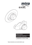
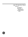
RAIN
BIRD
®
RAIN BIRD NATIONAL SALES, Inc. Customer Support Center
6991 E. Southpoint Rd., Bldg. #1, Tucson, AZ 85706 1-800-RAIN-BIRD (520) 434-6290 FAX
HOMEOWNER'S GUIDE TO
WINTERIZATION
In a freezing climate it is advisable to "winterize" the sprinkler system in order to avoid
damage. Special attention should be given to removing water from the pipes, valves,
and sprinkler heads, before freezing occurs. This may be accomplished using three
techniques; the manual drain valve method, the automatic drain valve system, or the
air blow-out practice. Caution! Please refer to the How to Winterize System
Components section to fully complete the winterization process for your system.
MANUAL DRAIN VALVE DESIGN AND PROCEDURE
Design: The manual drain valve should be installed on the sprinkler system mainline
at the lowest point of the system. Additional manual drain valves must be installed if
there are multiple low points along the run of pipe where water collection might occur.
A ball valve, gate valve, "Stop and Waste" valve, or a simple threaded pipe with a cap
may be used to provide drainage. Piping should be sloped properly to allow water to
drain out. If the valve is located outdoors, it should be installed over a "dry-well"
(underground pit filled with gravel to drain water away from the piping) to allow the
amount of water that is drained to percolate into the soil. If the valve is installed indoors, make sure the volume of water can be collected or drained without the risk of
overflow or flooding.
Meter In House
Service to
House
Compression
Tee
C
A
To Control
Valves
Shutoff Valve
Drain Cap
Water Meter
Shutoff
Slope Downward
for Drainage
Shutoff
B
Sevice Line
from Street
1
Procedure: Wear proper eye protection. The manual drain valve or drain cap is
pressurized at this time and could cause physical injury if opened before the pressure
is first relieved. Please follow the steps below carefully .
1. Turn off the sprinkler system mainline shut off valve. ( A )
2. Open one of the sprinkler system control valves, either manually, or electrically from
the timer, to relieve pressure on the sprinkler system mainline.
3. Slowly open the manual drain valve. ( B )
4. Repeat this procedure for all manual drain valves on the sprinkler system mainline.
5. Caution! Please refer to the How to Winterize System Components section to
fully complete the winterization process for your system.
AUTOMATIC DRAIN VALVE DESIGN AND PROCEDURE
Description: Please refer to the Manual Drain Valve section for mainline winterization. Caution! Do not install automatic drain valves on the sprinkler system
mainline! The automatic drain valve, model 16A-FDV, is a spring loaded device which
is installed on the sprinkler pipes or heads. It is a convenient and efficient product for
removing water from the lateral pipe network running from the sprinkler system control
valves to the heads. Automatic drains should be installed after or downstream of the
sprinkler control valves. They are not designed or engineered for use on mainlines.
The drain valve will open every time the system is shut off. This will drain all the water
out of the pipe providing the valve is installed at the proper location, which is the low
point on the line. When the system is pressurized, the water shuts the valve off by
pressing against the sealing mechanism, allowing water to flow through the pipe and
on to the sprinklers in proper fashion.
16 A-FDV
Drain Valve
Clean Gravel
Design: Install automatic drain valves at the low points in the sprinkler lines. Generally speaking, one or two drains per line are adequate to do the job. The drain valves
1
3
have either /2”or /4” male pipe threads. Use two or three wraps of PTFE tape around
the threads to ensure a proper seal. Simply screw the drain valve into a threaded fitting positioned downward. If you have a soil condition which drains poorly, we suggest
digging a small hole directly beneath the drain and filling it with clean gravel to assist
drainage.
Procedure: Automatic drain valves remove water from the system every time it is shut
off. No manual intervention should be required. Check for excessive puddling on the
soil surface should one of the drains become stuck open during sprinkler operation.
2
HOW TO BLOW WATER OUT OF THE LINES USING COMPRESSED AIR
CAUTION! WEAR PROPER EYE PROTECTION! Extreme care must be taken
when blowing out the system to avoid excessive pressure which can damage
valves or sprinkler pipe or cause physical injury due to flying debris. Do not
stand over any irrigation components (pipes, sprinklers, and valves) during air
blow out. Air pressure must not exceed 50 pounds per square inch (psi). Local
irrigation contractors usually offer this service for a reasonable fee which may also include start-up in the Spring. Depending on how extensive your system is and what
type of equipment you have installed, you may want to choose a professional who is
fully equipped to provide this service.
Description: Compressed air is used to force water through all of the irrigation system
components including the mainline pipe, sprinkler control valves, lateral pipes, and out
through the sprinkler heads. To obtain proper air volume, you will need to rent or buy
a compressor capable of providing 10 to 25 cubic feet per minute (CFM) of air volume. Air pressure must not exceed 50 pounds per square inch (psi) during the
blow -out procedure. A pressure regulating valve must be used to avoid overpressurization of the system. Air volume should be high and air pressure low. This combination of high volume and low pressure will minimize the damage that can occur during the winterization process. It is very important to select the right air compressor for
the job. Some small shop compressors (2 hp) may not be adequate to complete the
winterization procedure properly.
If the appropriate air compressor is not available, please call an irrigation contractor.
Do not try to use an air compressor with high pressure (120 psi) and low volume to
evacuate water from the system. It is not an acceptable practice to allow the compressor to fill the holding tank of the compressor and the closed mainline with high pressure air, hoping the surge of excess pressure will compensate for the lack of compressor size and blow the line clean upon opening the sprinkler control valve. This is a
dangerous practice that places very severe stresses on all of the components of the
system. Do not run the compressor without at least one sprinkler control valve
open. This lessens the chance that the system could overpressurize. It is a common
misbelief that if the system can withstand 120 psi of water pressure, similar air pressure will not damage the system. This is not true! The viscosity of air is much lower
than water, generating much higher stresses that can cause severe damage to the
system.
Design: There should be a separate provision on the sprinkler system mainline for
booking up the air hose (see item C in the diagram on the next page). This could be a
quick connect fitting, a manual gate valve, a plugged "tee", or simply a capped pipe in
the line. This adapter should be located as close to the water source as possible.
Check with your air compressor manufacturer for the correct procedure and equipment
to hook up to the sprinkler system.
3
Meter In House
Service to
House
Compression
Tee
C
A
To Control
Valves
Shutoff Valve
Drain Cap
Water Meter
Shutoff Valve
Slope Downward
for Darinage
Shutoff Valve
B
Service Line
from Street
Procedure: Wear Proper Eye Protection! Do not stand over any irrigation components (pipe, valves, or sprinklers) during air blow out. Do not run the air compressor without a sprinkler zone control valve being open first, from start up to
compressor shut down. Air pressure must not exceed 50 pounds per square
inch (psi).
Blow out procedure activating sprinkler control valves from the timer:
1. Close mainline sprinkler shutoff valve. ( A )
2. Relieve the water pressure on the mainline by activating a circuit, or zone, from
your timer. Activate the circuit that is furthest from the air connection before
introducing air into the piping.
3. Attach the compressor hose to the blow out adapter. ( C )
4. Set the pressure regulating valve on the compressor to 50 psi.
5. Turn on the compressor. Gradually increase the flow of air until the sprinkler heads
pop up. The amount of flow or volume required will be dependent upon the length
of the pipe run and the number of heads.
6. Sustained heat from the compressed air may damage pipe and other components.
Do not blow any circuit more than 2 minutes at a time. Switch to another station, or zone, by advancing the timer to the next circuit. Do not turn the timer off
at any time during this operation until the compressor is first shut off.
7. In order to ensure adequate drainage of lines, repeat the cycle two or more times,
activating each zone from the timer, until nothing more than a fine mist appears
from the heads. Many sprinklers that use plastic gears in their drive mechanisms
also use water for lubrication and cooling. If a circuit is allowed to run with nothing
but air for extended periods there is a significant risk of damaging the drive mechanism of the sprinkler.
8. After blowing out all the zones, leave one zone on while shutting down the compressor. Turn the compressor off at this time.
9. Unhook the compressor from the adapter to the sprinkler system mainline.
10. Turn the timer to "Off".
11. Caution! Please refer to the How to Winterize System Components section to
fully complete the winterization process for your system.
4
Procedure: Wear Proper Eye Protection! Do not stand over any irrigation components (pipes, valves, or sprinklers) during air blow out. Do not run the air
compressor without an irrigation control zone valve being open first, from start
up to compressor shut down.
Please refer to Blow Out Procedure Activating Valves from Timer section before
considering this alternative. Activating the valves from the timer offers an additional
margin of safety to the procedure since you would not be placed in close proximity to
the irrigation components during the blow out.
Use this section only if your system does not have electric remote control valves.
Blow out procedure activating valves manually:
1. Close main sprinkler shutoff valve. ( A )
2. Relieve the water pressure on the mainline by slowly opening the manual shutoff
handle on one of your irrigation zone control valves.
3. Attach the compressor hose to the blow out adapter. ( C )
4. Set the pressure regulating valve on the compressor to 50 psi.
5. Turn on the irrigation station you want to blow out.
6. Turn on the compressor. Gradually increase the flow of air from the compressor
flow valve (not from the sprinkler control valve) until the sprinkler heads pop up.
The amount of flow or volume required will be dependent upon the length of the
pipe run and the number of heads.
7. Sustained heat from the compressed air may damage pipe and other components.
Do not blow any circuit more than 2 minutes at a time.
8. After 2 minutes, turn the compressor off, and allow all of the air to completely
purge from the compressor tank and the sprinkler system.
9. Turn on the next irrigation control valve you wish to winterize.
10. Turn off the last irrigation control valve you have just blown out.
11. Repeat Steps 5 through 10 until you have completed 2 or more blow out cycles
per zone. There should only be a fine mist blowing from each station if the
winteriza-tion procedure was successful. Cycle again as needed.
12. Turn the compressor off. Allow any air in the storage tank or irrigation components
to disperse before approaching the air hose or valves.
13. Unhook the compressor from the adapter to the sprinkler mainline.
14. Caution! Please refer to the How to Winterize System Components section to
fully complete the winterization process for your system.
HOW TO WINTERIZE SYSTEM COMPONENTS
Valves: Gravity draining of the system will not remove water captured inside the
valves. Activating the valves manually or electrically from the timer is not an effective
way to drain then. Valves that are not blown out with air must follow this procedure:
Any diaphragm style such as the DAS-075, DAS-100, CP-075, CP-100, CPF-075,
CPF-100, and EV-100 should be disassembled and drained. Remove the bonnet,
solenoid, and diaphragm assembly and drain or sponge any standing water, then reassemble. Leave solenoid in open position for winter.
5
Actuator type valves such as the APAS-075, APAS-100, AVG-075, and AVG-100 require removal of the stem and solenoid assembly, check for any standing water in the
pipe. Manual valves such as the PAS-075 and PAS-100 may simply be left in the open
position for the Winter. Valves that are winterized using the blow out method with
compressed air do not require disassembly to remove standing water. Leave the
valves in the manual open position to prevent possible repressurization during the
Winter. This is accomplished by turning the bleed screw or solenoid counterclockwise,
to the open position.
Sprinkler Heads: If your system uses automatic drain valves (Model 16A-FDV) installed properly at the low point of the system, the sprinkler lines will drain automatically each time the system is shut off. This should drain the water from the sprinkler
heads also. Some sprinklers have both side and bottom pipe inlets. If you use the side
inlet, install a drain valve on the bottom inlet to prevent the case from freezing. Sprinkler heads containing built in check valves to prevent low head drainage require disassembly, or must be blown out with air to achieve proper winterization. These types
of heads are usually found only on commercial installations. Sprinklers that have been
blown out with air generally do not require and additional treatment.
Timers: Several methods for winterizing timers are available. Some may be more appropriate for your particular application, depending on the model you own, systems
utilizing water pumps require special attention here. Read the entire section before
deciding which method is correct for you.
1. If your sprinkler system does not have a water pump and your timer has a programming dial or a mechanical on/off switch: Turn the timer to the "OFF" position. Leave the timer plugged in. The program you set will remain intact. You may
leave the back up battery plugged in on electronic models. Leaving the timer
plugged in keeps some heat inside the unit, warding off condensation which may be
harmful to the circuit board. Timers such as the ISA-304, ISA-406, ISA-408, PC506, ESP-12LXi, ESP-16LXi, or any mechanical timer like the RC-7C series (the
type that has pins and dials), may simply be turned to OFF, RAIN, or RAIN/OFF to
achieve proper winterization.
2. If your sprinkler system does not have a water pump and your digital electronic timer has a "keypad" only: Press the "SYSTEM/OFF" or "AUTO/OFF"
key. This will turn the system off, leaving the program in the memory. A single digit
flashing in the display indicates the system is interrupted, giving visual confirmation.
Caution! A power surge or prolonged power failure could cause the timer to default
back to the automatic mode, sending a signal to the irrigation control valves or
pump to come on. This will not hurt the valves, but could do serious damage to a
"dry" running pump. Examples of this type of timer are the PC-104, PC-106, PC204, PC-206, TSC-7, EZ-1, and the CRC-4/6/8.
6
3. If your sprinkler system has a water pump and your timer is in an indoor digital electronic or mechanical model: Unplug the timer. Turning the timer off from
the keypad does not guarantee complete security from the timer coming on again in
case of a power surge or power failure. Mechanical models turned off from the
switch can just as easily be reactivated. Indoor models have a power cord attached
to a transformer style plug. Simply unplug the transformer from the power source.
The transformer is a small black box that is usually warm or hot to the touch. Warning! Grabbing a hot transformer could cause burns. Use gloves to protect your
hands. Next, remove the backup battery (digital models) to prevent it from discharging over the Winter. Be advised that this method causes the program to disappear
on digital models. You will have to reprogram the timer next spring. Examples of this
type of timer are the PC-104-P/S, PC-106-P/S, PC-204-P/S, PC-206-PS, TSC-7,
EZ-1, and RC-7Bi (or any Rain Bird RC-Bi or RC-I series).
4. If your sprinkler system has a water pump and your timer is an outdoor digital
electronic or mechanical model, follow these steps carefully: Turning the timer off
from the keypad does not guarantee complete security from the timer coming on
again in case of a power surge or power failure. Mechanical models turned off from
the switch can just as easily be reactivated. To correctly winterize these types of
timers, the common wire(s) running to the pump start relay and the valves
must be disconnected from the timer. Turn the power source to the timer off at
the main circuit breaker panel for your home or garage first. These timers are "hard
wired" directly into the high voltage circuit of your electrical system. The power
wires run directly through conduit pipe to the timer. Warning! Touching high voltage wires can cause electrical shock and burns. Do not attempt to disconnect
these wires to de-power the timer. The power may only be turned off at the main
circuit breaker panel. Verify that the power is completely off by removing the backup
battery. Wait for 2 minutes. If the digital display on the timer has not gone blank,
please call Rain Bird, or an irrigation contractor to assist you. If you have verified
that the power is off to the timer, proceed to disconnect the wire or wires marked
"Common", "Com", or "C", on the timer terminal strip. This is the location in the timer
where the valve wires connect. Usually there is a row of screws that are labeled and
numbered. Locate the terminal designated as COMMON, COM, or C. In some
cases there may be 2 terminals marked for the common wire. Disconnect all of the
wires from the common terminal. Twist a wire nut or place a piece of electrical tape
over any loose wire ends to prevent the wire(s) from touching and causing a short
circuit. Reconnect the backup battery on digital models. Mechanical models: Many
Rain Bird mechanical timers have a valve wiring harness that may simply be unplugged to disconnect the common and station wires altogether. This is usually a
white multi-pin "snap" connector (Molex type) located behind the face panel, inside
the cabinet. Close the timer access panel. Turn the power source back on to the
timer. Be sure to go ahead and program the timer to the "OFF" setting on the keypad or switch. Set the station timing to zero minutes for all of the stations to prevent
any operation. In the Spring, reconnect the common wires and reprogram the timer.
7
Backflow Preventer: Please check with the manufacturer for specific winterization
techniques. Leave the shutoff valves open after draining the unit. “Ball” type shutoff
valves should be left at a 45 degree angle to prevent water from entering the seal.
Under extreme conditions, insulate the device or use “heat tape” to prevent damage.
Pump: Please check the pump manufacturer’s instructions for winterization. See
timer section regarding pumps.
8