1
452/453/457
LCD TV
Installation manual
imagine the possibilities
Thank you for purchasing this Samsung product.
To receive more complete service, please register
your product at
www.samsung.com/register
Model
LC452_453_457-hotel.indd 1
Serial No.
2010-04-12 오후 8:37:19
Figures and illustrations in this User Manual are provided for reference only and may differ from actual product appearance.
Product design and specifications may be changed without notice.
Instruction
This TV is provided with interactive functionality through a set-back box (SBB/STB) connected to the TV, and with other TVs in a computer controlled
system for hotels and other hospitality businesses.
Interactive : When the TV is powered-up initially, it sends a command to identify the SBB/STB; if identified, theTV switches to ONLINE mode and full
control is through the SBB/STB.
If the TV is in ONLINE mode, it stops receiving IR(Samsung remote) commands and acts according to interface protocol.
Stand-Alone: If SBB/STB is not identified, the TV should be switched to STAND-ALONE mode with restricted operation.
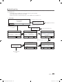
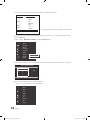
Operational Modes
When this TV (in Hotel mode) is operated with a SBB/STB, it is in one of two states
• ONLINE or STAND-ALONE. In the STAND-ALONE state, the TV will act as a Hotel TV, but without active communication. This is to prevent guests
from trying to cheat the system by disconnecting the SBB/STB.
Hotel TV
Hotel Mode On
SBB/STB Onlineif one
success within 10
attempts
Power
ON
Stand-alone
Mode
SBB/STB
Online-10
consecutive
fails
SBB/STB
StatusAttempt
every 2secs
Normal TV
Hotel Mode Off
Online Mode
Poll Rate 20/sec
To set the details for Stand-alone or interactive mode, refer to pages 22-25(Setting the hotel option data : Stand-alone mode and Interactive mode)
• Some operations may be restricted to prevents guests from "cheating" the TV system.
• No main menu(Interactive mode) or Channel Menu, Plug & Play in Main Menu(Stand-Alone mode)
• Limited Volume and Panel key lock or unlock
Still image warning
Avoid displaying still images (like jpeg picture files) or still image element (like TV Program logo, panorama or 4:3 image format, stock or news bar at screen
bottom etc.) on the screen. Constant displaying of still picture can cause uneven wear of screen phosphor, which will affect image quality. To reduce risk of
this effect, please follow below recommendations:
• Avoid displaying the same TV channel for long periods.
• Always try do display any image on full screen, use TV set picture format menu for best possible match.
• Reduce brightness and contrast values to minimum required to achieve desired picture quality, exceeded values may speed up the burnout process.
• Frequently use all TV features designed to reduce image retention and screen burnout, refer to proper user manual section for details.
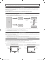
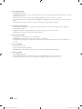
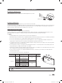
Securing the Installation Space
Keep the required distances between the product and other objects (e.g. walls) to ensure proper ventilation.
Failing to do so may result in fire or a problem with the product due to an increase in the internal temperature of the product.
✎✎ When using a stand or wall-mount, use parts provided by Samsung Electronics only.
xx If you use parts provided by another manufacturer, it may result in a problem with the product or an injury due to the product falling.
✎✎ The appearance may differ depending on the product.
Installation with a stand.
Installation with a wall-mount.
10 cm
10 cm
10 cm
10 cm
10 cm
10 cm
10 cm
LC452_453_457-hotel.indd 2
2010-04-12 오후 8:37:20
Contents
Accessories............................................................................................................................................................... 4
Install the Stand......................................................................................................................................................... 4
How to Adjust the Stand (19inch model only)............................................................................................................. 5
How to Adjust the Angle of the TV (19inch model only).............................................................................................. 5
Installing VESA Compliant Mounting Devices (19inch model only).............................................................................. 6
Using the Decoration Covers (19inch model only)...................................................................................................... 6
Installing the LCD TV Stand (19inch model only)....................................................................................................... 7
Viewing the Connection Panel.................................................................................................................................... 8
Viewing the Control Panel........................................................................................................................................ 12
Viewing the Remote Control..................................................................................................................................... 13
Connecting the Bathroom Speakers........................................................................................................................ 17
Installing the Wall Mount.......................................................................................................................................... 35
Securing the TV to the Wall ..................................................................................................................................... 36
Assembling the Cables............................................................................................................................................ 36
Anti-theft Kensington Lock....................................................................................................................................... 37
Specifications.......................................................................................................................................................... 37
English
LC452_453_457-hotel.indd 3
ENGLISH
yy
yy
yy
yy
yy
yy
yy
yy
yy
yy
yy
yy
yy
yy
yy
yy
3
2010-04-12 오후 8:37:20
Accessories
✎✎Please make sure the following items are included with your LCD TV. If any items are missing, contact your dealer.
✎✎The items’ colour and shapes may vary depending on the models.
yy Remote Control & Batteries (AAA x 2)
yy Cleaning Cloth
yy Owner’s Instructions
yy Power Cord / Data Cable
yy Warranty Card / Safety Guide / Registration Cards (Not available in all locations)
Blanking Bracket
✎✎The stand and stand screw may not be included depending on the model.
✎✎The Data Cable may not be included depending on the SI Vendor.
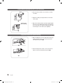
Install the Stand
✎✎Preset: Place the Guide Stand and Cover Neck onto
the stand and fasten it using the screws.
1. Attach your LCD TV to the stand.
Two or more people should carry the TV.
✎✎
✎✎ Make sure to distinguish between the front and
back of the stand when assembling them.
✎✎ To make sure the TV is installed on the stand at
a proper level, do not apply excess downward
pressure to the upper left of right sides of the
TV.
2. F
asten two screws at position 1 and then fasten two
screw at position 2.
Stand the product up and fasten the screws. If
you fasten the screws with the LCD TV placed
down, it may lean to one side.
✎✎
✎✎ The stand is installed for models with the
screen size of 37 inch and above.
4
English
LC452_453_457-hotel.indd 4
2010-04-12 오후 8:37:21
How to Adjust the Stand (19inch model only)
1. Place the front of the TV onto a soft cloth or
cushion on a table as in Figure 1.
✎✎ Align the TV bottom along the table edge.
1
2. Press on the center of the TV back. Adjust the
stand as in Figure 2 while
✎✎ pressing the button on the back of the stand.
3. Place the TV on the table so that the TV sits safely
on the table.
2
How to Adjust the Angle of the TV (19inch model only)
✎✎When you adjust the stand, press the button on the
back of the stand.
1. Figure 1 shows the adjustment angle (-2°~14°)
when you use the LCD on its stand. Excessive
tilting can turn the LCD TV over which may cause
damage.
1 A
ngle adjustment
when using the TV
on its stand.
2. Figure 2 shows the adjustment angle (14°~80°)
when you convert the LCD from stand-based use
to wall-mount.
2 Angle adjustment when
converting from Stand to Wall
mount (1→3, 3→1)
3. Figure 3 shows the adjustment angle (0°~10°)
when you mount the LCD TV to a wall.
✎✎ You will hear a "Click" sound when changing
the angle from 1 to 2 or 3 to 2.
3 Angle adjustment
when LCD TV is
wall-mounted
English
LC452_453_457-hotel.indd 5
5
2010-04-12 오후 8:37:22
Installing VESA Compliant Mounting Devices (19inch model only)
Button
1. Place the TV face down on a soft cloth or cushion
on a table.
2. Adjust the stand, pressing the button on the back
of the stand.
1
Mounting pad
(Sold separately)
3. Align the mounting interface pad (not supplied) with
the holes in the stand bottom and secure it with the
four screws that come with the arm-type base, wall
mount hanger or other bases (not supplied).
2
Using the Decoration Covers (19inch model only)
1. When installing the TV on the wall without using the
stand, insert decoration covers into the holes as
described in the picture 1.
1
2. After inserting the decoration covers, fasten them
with 4 screws as described in the picture 2.
2
6
English
LC452_453_457-hotel.indd 6
2010-04-12 오후 8:37:23
Installing the LCD TV Stand (19inch model only)
If any items are missing, contact your dealer.
✎✎When installing the stand, use the provided components and parts.
ⓐ Screws: 3EA ⓑ Screws: 4EA
Stand
Cover Neck
1
Guide Stand
Screws
2
Back
Front
3
4
Position 2
Front
Back
Position 1
1. Insert the Cover Neck into the groove of the stand. Assemble the LCD TV stand by aligning the triangle
figures indicated by the arrow marks.
2. Place the Guide Stand onto the stand which is assembled in step 1 and fasten it using the three ⓐ screws.
3. Connect your LCD TV and the stand.
4. Fasten two ⓑ screws at position 1 and then fasten two 1 screws at position 2.
Caution
✎✎Make sure to distinguish between the front and back of each component when assembling them.
✎✎Make sure that at least two persons lift and move the LCD TV.
✎✎Stand the product up and fasten the screws. If you fasten the screws with the LCD TV placed down,
it may lean to one side.
English
LC452_453_457-hotel.indd 7
7
2010-04-12 오후 8:37:24
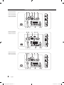
Viewing the Connection Panel
LE32C452C4HXXC
LE32C453C4HXXC
LA32C457C6HXZN
LA37C457C6HXZN
LA40C457C6HXZN
1 2 3
4
6
7
HDMI IN3
ANT IN
4
8
9
Power Input
%
LE32C457C6HXXC
LE37C457C6HXXC
LE40C457C6HXXC
$
@
#
1 2 3
4
!
5 6
0
7
HDMI IN3
5Vdc/2.5A
(12Vdc/1.5A)
ANT IN
4
8
9
Power Input
%
LE26C452C4HXXC
LE26C453C4HXXC
LA26C457C6HXZN
$
@
#
1 2 3
4
!
6
0
7
HDMI IN3
ANT IN
4
8
9
Power Input
%
8
$
#
@
!
0
English
LC452_453_457-hotel.indd 8
2010-04-12 오후 8:37:25
LE26C457C6HXXC
2 3
1
4
5
7
6
HDMI IN3
5Vdc/2.5A
(12Vdc/1.5A)
ANT IN
4
8
9
Power Input
%
LE19C452C4HXXC
LE19C453C4HXXC
LE22C452C4HXXC
LE22C453C4HXXC
LE22C457C6HXXC
$
$
@
#
8
4
!
6
0
7
AV IN
9
3
Power Input
#
@
0
✎✎Whenever you connect an external device to your TV, make sure that power on the unit is turned off.
✎✎When connecting an external device, match the color of the connection terminal to the cable.
1 VARIABLE AUDIO OUT: Used for the audio output to the Bathroom speaker. Connect the Bathroom Wall Box and the
Variable port (RCA). (Not available for 19/22 inch model.)
2 VOL-CTRL: Used to control the volume of the Bathroom speaker. Connect the Bathroom Wall Box and the VOL-CTRL
port.
3 ANT IN: To view television channels correctly, a signal must be received by the set from one of the following sources. An
outdoor antenna / A cable television network / A satellite network.
✎✎ For Norway: Utstyr som er koplet til beskyttelsesjord via nettplugg oq/eller via annet jordtilkoplet utstyr-og er tilkoplet
et kabel-TV nett, kan forårsake brannfare. For å unngå dette skal det ved tilkopling av utstyret til kabel-TV nettet
installeres en galvanisk isolator mellom utstyret og kabel-TV nettet.
✎✎ For Sweden: Utrustning som är kopplad till skyddsjord via jordat vägguttag och/eller via annan utrustning och
samtidigt är kopplad till kabel-TV nät kan i vissa fall medfőra risk főr brand. For att undvika detta skall vid anslutning
av utrustningen till kabel-TV nät galvanisk isolator finnas mellan utrustningen och kabel-TV nätet.
4 HDMI IN 1(DVI), 2, 3: Connects to the HDMI jack of a device with an HDMI output.
✎✎ No sound connection is needed for an HDMI to HDMI connection.
✎✎ Use the HDMI IN 1 jack for DVI connection to an external device. Use a DVI to HDMI cable or DVI-HDMI adapter
(DVI to HDMI) for video connection and the PC/DVI AUDIO IN jacks for audio.
5 5V DC/2.5A (12V DC/1.5A): Used to supply power for the SBB or STB. (Available for B457 26/32/37 inch model only.)
6 PC/DVI AUDIO IN: connect to the audio output jack on your PC
English
LC452_453_457-hotel.indd 9
9
2010-04-12 오후 8:37:26
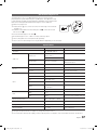
7 PC IN: Connect to the video output jack on your PC.
Display Modes
Both screen position and size will vary depending on the type of PC monitor and its resolution.
The resolutions in the table are recommended.
✎✎Optimal resolution is 1360 X 768 @ 60 Hz. (Only for 19" 22" 26" 32" models)
Mode
Resolution
Horizontal Frequency
(KHz)
Vertical Frequency
(Hz)
Pixel Clock
Frequency
(MHz)
Sync Polarity
(H / V)
IBM
640 x 350
720 x 400
31.469
31.469
70.086
70.087
25.175
28.322
+/-/+
MAC
640 x 480
832 x 624
35.000
49.726
66.667
74.551
30.240
57.284
-/-/-
VESA CVT
720 x 576
1280 x 720
35.910
56.456
59.950
74.777
32.750
95.750
-/+
-/+
VESA DMT
640 x 480
640 x 480
640 x 480
800 x 600
800 x 600
800 x 600
1024 x 768
1024 x 768
1024 x 768
1280 x 720
1360 x 768
31.469
37.500
37.861
37.879
46.875
48.077
48.363
56.476
60.023
45.000
47.712
59.940
75.000
72.809
60.317
75.000
72.188
60.004
70.069
75.029
60.000
60.015
25.175
31.500
31.500
40.000
49.500
50.000
65.000
75.000
78.750
74.250
85.500
-/-/-/+/+
+/+
+/+
-/-/+/+
+/+
+/+
VESA GTF
1280 x 720
52.500
70.000
89.040
-/+
✎✎Optimal resolution is 1920 X 1080 @ 60 Hz. (Only for 37“ 40” models)
10
Mode
Resolution
Horizontal Frequency
(KHz)
Vertical Frequency
(Hz)
Pixel Clock Frequency
(MHz)
Sync Polarity
(H / V)
IBM
640 x 350
720 x 400
31.469
31.469
70.086
70.087
25.175
28.322
+/-/+
MAC
640 x 480
832 x 624
1152 x 870
35.000
49.726
68.681
66.667
74.551
75.062
30.240
57.284
100.000
-/-/-/-
VESA CVT
720 x 576
1152 x 864
1280 x 720
1280 x 960
35.910
53.783
56.456
75.231
59.950
59.959
74.777
74.857
32.750
81.750
95.750
130.000
-/+
-/+
-/+
-/+
VESA DMT
640 x 480
640 x 480
640 x 480
800 x 600
800 x 600
800 x 600
1024 x 768
1024 x 768
1024 x 768
1152 x 864
1280 x 1024
1280 x 1024
1280 x 720
1280 x 800
1280 x 800
1280 x 960
1360 x 768
1440 x 900
1440 x 900
1680 x 1050
31.469
37.861
37.500
37.879
48.077
46.875
48.363
56.476
60.023
67.500
63.981
79.976
45.000
49.702
62.795
60.000
47.712
55.935
70.635
65.290
59.940
72.809
75.000
60.317
72.188
75.000
60.004
70.069
75.029
75.000
60.020
75.025
60.000
59.810
74.934
60.000
60.015
59.887
74.984
59.954
25.175
31.500
31.500
40.000
50.000
49.500
65.000
75.000
78.750
108.000
108.000
135.000
74.250
83.500
106.500
108.000
85.500
106.500
136.750
146.250
-/-/-/+/+
+/+
+/+
-/-/+/+
+/+
+/+
+/+
+/+
-/+
-/+
+/+
+/+
-/+
-/+
-/+
VESA GTF
1280 x 720
1280 x 1024
52.500
74.620
70.000
70.000
89.040
128.943
-/+
-/-
VESA DMT / DTV CEA
1920 x 1080p
67.500
60.000
148.500
+/+
English
LC452_453_457-hotel.indd 10
2010-04-12 오후 8:37:27
✎✎When using an HDMI / DVI cable connection, you must use the HDMI (DVI) IN 1 jack.
✎✎The interlace mode is not supported.
✎✎The set might operate abnormally if a non-standard video format is selected.
✎✎Separate and Composite modes are supported. SOG is not supported.
8 USB (HDD) / CLONING
–– Connector for software upgrades and Media Play, etc.
–– Service connection.
9 AV IN 1, 2
–– Connect a VIDEO cable to an appropriate external A/V device such as VCR, DVD or Camcorder.
–– Connect audio cables to [R-AUDIO-L] on your TV and the other ends to corresponding audio out jacks on the A/V device.
0 DATA
–– Used to support data communication between the TV and the SBB.
–– The TV jack type is RJ-12.
! RJP: This port is an RJP (Remote Jack Pack) communication port that enables connecting different devices to additional
module so as to improve device use convenience.
@ COMPONENT IN
–– Connects Component video / audio.
–– Connect component video cables (optional) to the component jacks ("PR", "PB", "Y") on the rear of your TV and the
other ends to corresponding component video out jacks on the DVD.
–– If you wish to connect both the Set-Top Box and DVD, you should connect the Set-Top Box to the DVD and connect
the DVD to the component jacks ("PR", "PB", "Y") on your TV.
–– The PR, PB and Y jacks on your component devices (DVD) are sometimes labeled Y, B-Y and R-Y or Y, Cb and Cr.
–– Connect RCA audio cables (optional) to [R - AUDIO - L] on the rear of the TV set and the other ends to corresponding
audio out jacks on the DVD.
# EXT
Connector
EXT
Input
Output
Video
Audio (L/R)
RGB
Video + Audio (L/R)
0
0
0
Only TV or DTV output is available
✎✎Inputs or outputs for external devices, such as VCR, DVD, video game device or video disc players.
$ Headphones jack: Headphones may be connected to the headphone jack on your TV. While the headphones are
connected, the sound from the built-in speakers will be disabled.
% HP-ID: Enables to identify whether a headphone jack is inserted into the additionally created head phone box.
English
LC452_453_457-hotel.indd 11
11
2010-04-12 오후 8:37:27
Viewing the Control Panel
✎✎The product colour and shape may vary depending on the model.
Remote control sensor
Power Indicator
Speakers
SOURCEE
MENU
y
z
P (Power)
Remote control sensor
Power Indicator
Toggles between all the available input sources. In the on-screen menu, use this
button as you would use the ENTERE button on the remote control.
Displays an on-screen menu, the OSD (on screen display), of your TV’s features.
Adjusts the volume. In the OSD, use the y buttons as you would use the ◄
and ► buttons on the remote control.
Changes the channels. In the OSD, use the z buttons as you would use the
▼ and ▲ buttons on the remote control.
Turns the TV on or off.
Aim the remote control towards this spot on the TV.
Blinks and turns off when the power is on and lights up in standby mode.
Standby mode
Do not leave your TV in standby mode for long periods of time (when you are away on a holiday, for example). A small amount
of electric power is still consumed even when the power button is turned off. It is best to unplug the power cord.
12
English
LC452_453_457-hotel.indd 12
2010-04-12 오후 8:37:27
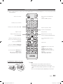
Viewing the Remote Control
✎✎This is a special remote control for the visually impaired persons and has Braille points on the Power, Channel and
Volume buttons.
POWER
SOURCE
Turns the TV on and off.
Display and select the available video
sources.
Selects the HDMI mode directly.
HDMI
Have direct access to channels.
Alternately selects Teletext, Double or Mix.
PRE-CH
TTX/MIX
Return to the previous channel.
Cut off the sound temporarily.
Adjust the volume.
Change channels.
CH LIST
Display channel list on the screen.
Display the main on-screen menu.
MENU
View the Media Play.
MEDIA.P
GUIDE
Quickly select frequently used functions.
TOOLS
INFO
RETURN
EXIT
Select on-screen menu items and change
menu values.
Return to the previous menu.
Buttons in the Channel list, Media Play
menu, etc.
Enter the hour your want the TV to turn on.
A
@ TV
B
C
D
ǎǏ
INTERNET
S.MODE
DUAL
ALARM
P.SIZE
SUBT.
Use these buttons in the Media Play and
Anynet+ modes.
(�: controls recording on Samsung
recorders with the Anynet+ feature)
Electronic Programme Guide (EPG) display.
Press to display information on the TV
screen.
Exit the menu.
INTERNET@TV: Link to various internet
services.
S.MODE: Select the sound mode.
DUAL f-g: Sound effect selection.
ALARM: Enter the hour you want the TV
to turn on.
P.SIZE: Choose the picture size.
SUBT.: Displays digital subtitles.
Installing batteries (Battery size: AAA)
✎✎NOTE
xx Use the remote control within 23 feet from the TV.
xx Bright light may affect the performance of the remote
control. Avoid using nearby special fluorescent light or neon
signs.
xx The colour and shape may vary depending on the model.
English
LC452_453_457-hotel.indd 13
13
2010-04-12 오후 8:37:27
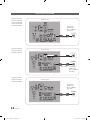
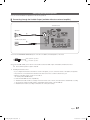
Connecting the TV with SBB
LE32C452C4HXXC
LE32C453C4HXXC
LA32C457C6HXZN
LA37C457C6HXZN
LA40C457C6HXZN
TV Rear Panel
Hotel Server
STB(Set Top
Box) or SBB(Set
Back Box)
ANT 2 IN
(CABLE)
ANT 1 IN
(AIR)
ETH MODEM
Data Cable
LE32C457C6HXXC
LE37C457C6HXXC
LE40C457C6HXXC
TV Rear Panel
ANT IN
DC-POWER
5Vdc/2.5A
(12Vdc/1.5A)
DC Cable
ETH MODEM
Data Cable
LE26C452C4HXXC
LE26C453C4HXXC
LA26C457C6HXZN
Hotel Server
STB(Set Top
Box) or SBB(Set
Back Box)
TV Rear Panel
ANT IN
Hotel Server
STB(Set Top
Box) or SBB(Set
Back Box)
ETH MODEM
Data Cable
14
English
LC452_453_457-hotel.indd 14
2010-04-12 오후 8:37:28
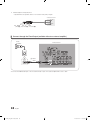
LE26C457C6HXXC
TV Rear Panel
ANT IN
DC-POWER
5Vdc/2.5A
(12Vdc/1.5A)
DC Cable
ETH MODEM
Data Cable
Hotel Server
STB(Set Top
Box) or SBB(Set
Back Box)
LE19C452C4HXXC
LE19C453C4HXXC
LE22C452C4HXXC
LE22C453C4HXXC
LE22C457C6HXXC
AV IN
Hotel Server
STB(Set Top
Box) or SBB(Set
Back Box)
ETH MODEM
Data Cable
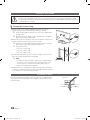
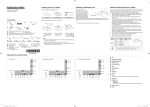
1.Connect the [DATA] jack of the TV to the [ETH MODEM] jack of the STB(SBB) with the Data cable.
✎✎ Use data communication.
2.Connect the [Class 2 Wiring-5V DC/2.5A (12V DC/1.5A)] jack of the TV to the [DC-POWER] jack of the STB (SBB) with the
DC cable.
✎✎ The supported jack type differs depending on the STB (SBB) model.
✎✎ TV Jack Type: 6.5 Ø DC Power Jack
✎✎ Some STB (SBB) devices are not compatible with the data cable supplied with the TV.
English
LC452_453_457-hotel.indd 15
15
2010-04-12 오후 8:37:29
Warning
When you use the DC power output jack, you have to check the standard output
power of STB(SBB) and you should use the DC power within the standard
output(Class 2 Wiring-5V DC/2.5A (12V DC/1.5A).
–– For 5V SBB, SBB load current must not exceed 2.5A.
–– For 12V SBB, SBB load current must not exceed 1.5A.
–– The initial output is 5V.
–– For 12V SBB, you have to change the output voltage to 12V in order to use
the power.
Changing the Output Voltage (Only for EU C457 26" 32" 37" 40" model)
1.Press the POWER button.
✎✎ The TV is powered on.
2.Press the following remote control buttons in order.
INFO → MENU → 0 → 1 → EXIT
✎✎ The Hotel Option menu appears.
3.Press the ▲ or ▼ button to select DC Power Output.
Press the ◄ or ► button to select 12V or 5V.
4.Remove the power cord then plug it back in again.
✎✎ The voltage change is applied when you turn the TV on
again after changing the Interactive mode Option setting.
16
Hotel Mode
SI Vendor
Power On Channel
Channel Type
ON
RJP Priority AV
1
Logo Download
Samsung
RJP Priority PC
2
Logo Display Time
...
RJP Priority HDMI
3
Power On Option
Last Option
1
ATV
RJP AV Option
AV1
...
Auto Source
OFF
Energy Saving
Off
Power On Volume
10
RJP HDMI Option
HDMI1
Min Volume
0
Sub AMP Volume
6
Clone : TV to USB
Max Volume
100
Sub AMP Mode
2
Clone : USB to TV
Local Time
Manual
Pan Euro MHEG
OFF
Time Format
12 Hour
Cloning Data Reset
OFF
Failure
Welcome Message
3
Edit Welcome Message
2
DC Power Out
Panel Button Lock
Unlock
Power On Source
TV
Picture Menu Lock
OFF
Channel Editor
PMOLED Test
PMOLED Mormal Dim.
Music Mode AV
OFF
PMOLED Standby Dim.
Music Mode PC
OFF
Audio Loop In
OFF
Channel Auto Store
Music Mode Comp
OFF
Menu Display
ON
Dynamic SI
Music Mode Backlight
OFF
Hotel Logo
OFF
5V
OFF
English
LC452_453_457-hotel.indd 16
2010-04-12 오후 8:37:29
Connecting the Bathroom Speakers
You can connect the Bathroom Speakers in the following method.
¦¦ Connecting through the Variable Output (available without an external amplifier)
TV Rear Panel
ANT IN
5Vdc/2.5A
(12Vdc/1.5A)
Speaker
1
Volume Control Box
VOL+
2
VOL-
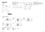
1.Connect the VARIABLE AUDIO OUT port of the TV to the Bathroom Wall Speakers of the hotel.
Signal wire : Speaker +
Shield wire : Speaker -
2.Connect the VOL-CTRL jack of the TV to the Volume Control Box Switch port of the Bathroom Wall of the hotel.
✎✎ The maximum speaker output is 4W, 8Ω.
yy Installing the Volume Control
–– If you configure the Volume Control Box as shown in the figure, you can control the volume of the bathroom speakers.
–– The jack that is connected from the Volume Control Box to the TV is a 3.5mm normal Phone jack.
–– Volume Control Box switch consists of Tact switch.
Setting the Sub AMP Mode
✎✎
–– 0: Turns the Sub AMP function off (PWM off).
–– 1: Determines the Sub volume according to the main volume control. That is, the sub volume is determined according
to the Power On Volume, the Min Volume, and the Max Volume values of the Hotel Mode.
–– 2: Determines the volume according to the bathroom control panel setting.
English
LC452_453_457-hotel.indd 17
17
2010-04-12 오후 8:37:30
yy Variable Output Port Specifications
–– Speaker Wire: Use speaker cable no more than 82 feet (25m) in length.
Volume Control Box
VOL +
1
3
2
VOL -
VOL - UP
GND
VOL - DOWN
( White 1 ) ( Black /Red 2 ) ( Shield Wire 3 )
¦¦ Connect through the Fixed Output (available without an external amplifier)
Audio
Amplifier
TV Rear Panel
AUDIO IN
1 Stereo
cable
1.Connect the AUDIO OUT port of the TV and the Audio In port of the audio amplifier with a stereo cable.
18
English
LC452_453_457-hotel.indd 18
2010-04-12 오후 8:37:30
Connecting the MediaHub HD
Output of any external source connected to MediaHub HD on hotel desk.
TV Rear Panel
MediaHub HD Rear
HDMI
ANT IN
USB
RS/232
5Vdc/2.5A
(12Vdc/1.5A)
2 HDMI cable
1 RS-232 Data Cable
1.Connect the RJP port of the TV and the RS/232 port of the MediaHub HD.
2.Connect the HDMI port of the TV and the HDMI port of the MediaHub HD.
yy MediaHub HD
–– The MediaHub HD is a hardware module that has different Audio Video inputs (A/V, Audio, PC, HDMI and USB) and
corresponding outputs. The corresponding output sources are connected from MediaHub to TV. The MediaHub
communicates with the TV via RS232. Hot Plug & Play is a function that allows hotel guests to connect an external
source to the MediaHub. The MediaHub communicates with the TV by sending messages regarding Active/Inactive
sources. The TV will switch to the Active external source.
–– You have to connect the HDMI of the MediaHub to the HDMI 1 port of the TV.
–– When the TV is on, connect the TV and the RJP within 10 seconds.
yy Special features
–– PIP
–– Bluetooth
–– Media Player (MediaHub HD+ only)
–– Auto Detection
English
LC452_453_457-hotel.indd 19
19
2010-04-12 오후 8:37:30
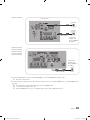
Connecting the RJP (Remote Jack Pack)
Output of any external source connected to RJP on hotel desk.
5
4 HDMI cable
HDMI
S-VIDEO RCA
AUDIO/PC
RS/232
ANT IN
5Vdc/2.5A
(12Vdc/1.5A)
HDMI IN3
USB
TV Side Panel
TV Rear Panel
RJP Rear
1 D-sub / PC Audio cable
or
2 Video / Audio Cable
3 Audio Cable
1.Connect the PC IN / PC/DVI AUDIO IN port of the TV to the PC/AUDIO port of the RJP.
2.Connect the AV IN [VIDEO]/[L-AUDIO-R] port of the TV to the S-VIDEO port of the RJP.
3.Connect the AV IN [VIDEO] port of the TV to the S-VIDEO port of the RJP.
4.Connect the HDMI port of the TV and the HDMI port of the RJP.
5.Connect the RJP port of the TV and the RS/232 port of the RJP.
✎✎ The RJP (Remote Jack Pack) compatible with this Samsung TV is TeleAdapt TA-7610, TA-7650 (HD) and TA-7660
(HD Plus).
yy RJP (Remote Jack Pack): RJP stands for Remote Jack Pack. The RJP is a hardware module that has different Audio
Video inputs (A/V, Audio, PC and HDMI) and corresponding outputs. The corresponding output sources are connected
from RJP to TV. The RJP communicates with the TV via RS232. Hot Plug & Play is a function that allows hotel guests
to connect an external source to the RJP. The RJP communicates with the TV by sending messages regarding Active/
Inactive sources. The TV will switch to the Active external source according to the priority set by the User.
You can select HDMI 1, 2, 3 and AV 1, 2 for connecting RJP.
✎✎
✎✎ When the TV is on, connect the TV and the RJP within 10 seconds.
yy The RJP can be returned to the factory default settings by pressing the A/V and HDMI buttons simultaneously for 10
seconds. All LEDs blink 5 times to Acknowledge that the rest has been performed.
yy The RJP will automatically turn off any LEDs after 5 minutes to avoid unnecessary light pollution in the hotel room. The
LEDs that were turned off will turn on again if the guest touches any of the buttons and the 5 minute timer will restart. If the
guest then touches another source button, the TV will change to the selected source and the corresponding LED will be lit.
yy After an RJP Reset or a TV Power OFF/ON, it takes approx. 10 seconds to establish communications between the TV and
the RJP.
20
English
LC452_453_457-hotel.indd 20
2010-04-12 오후 8:37:31
yy The following table shows the approximate time in seconds to switch from the TV to the input source, based on the
priority.
✎✎ Scenario 1: When no inputs are connected.
Source
To Connect
AV
PC
HDMI
2 Sec
0.7 Sec
3.9 Sec
✎✎ Scenario 2: When two or more inputs are connected and an Input source is disconnected and then reconnected.
Source
Disconnect
To Connect
Total
AV
PC
HDMI
4.5 Sec
0.7 Sec
3.9 Sec
2 Sec
0.7 Sec
3.9 Sec
6.5 Sec
1.4 Sec
7.8 Sec
✎✎ E.g. If the RJP has all its live sources AV, PC and HDMI connected, AV is viewed as the highest priority. If the RJP is
in HDMI mode, and a guest removes and reconnects the AV, the minimum time required to switch to the AV is 6.5
seconds.
yy To connect audio (Ipod or Mp3), Music mode should be ON and Jack Ident detect should be OFF.
yy A/V, PC and HDMI input sources are supported.
¦¦ Audio Loop In
An additionally created Headphone Box can be installed on a bed or business desk so that users can use it conveniently. The
installation procedures are given below. (Not available for 19/22 inch model.)
yy Detailed Drawing of the Headphone Box
TV Rear Panel
ANT IN
5Vdc/2.5A
(12Vdc/1.5A)
Headphone
Box
Headphone
Shield wire
Red Wire (Audio-R)
Shield wire
TV Headphones jack
Whitewire (Audio-L)
Red Wire + White wire
TV HP-ID jack
English
LC452_453_457-hotel.indd 21
21
2010-04-12 오후 8:37:31
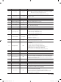
Setting the Hotel Option Data
¦¦ Standalone Mode
To Enter: Press the MUTE → 1 → 1 → 9 → ENTER buttons in order.
To Exit from this menu : power off and turn on again.
No
1
2
3
Item
Hotel Mode
SI Vendor
Power On Channel
initial Value
ON
OFF
1
4
Channel Type
ATV
5
6
7
Power On Volume
Min Volume
Max Volume
10
0
100
8
Panel Button Lock
Unlock
9
Power On Source
TV
10
Picture Menu Lock
OFF
11
Channel Editor
12
Music Mode AV
OFF
13
Music Mode PC
OFF
14
Music Mode Comp
OFF
15
Music Mode Backlight
OFF
16
RJP Priority AV
1
17
RJP Priority PC
2
18
RJP Priority HDMI
3
Description
Hotel mode(Stand alone) on/off
Select the SI Vendor
TV will switch on to this particular Channel
Provides channel Type description for Power On channel selected. i.e.
Selected channel analog or Digital & antannae selection(Air or Cable).
TV will switch on with this Volume Level
Minimum Volume Level setting user can set
Maximum Volume Level setting user can set
Front panel(Local key) operation on/off
- Unlock: Unlock All panel key
- Lock: Lock All panel key
- OnlyPower : Lock All panel key except Power panel key
Enable or disable Picture Menu
Provided option for editing Channel Name and Number and video
Mute settings for channels in channel List.
Provided option for editing Channel Name and Number and video
Mute settings for channels in channel List
To get music output from mp3/audio player in AV Input Source.
Audio enabled, video disabled in this mode
To get music output from mp3/audio player in PC Input Source.
Audio enabled, video disabled in this mode
To get music output from mp3/audio player in Component Input
Source.
Audio enabled, video disabled in this mode
Backlight On/Off option in Music mode to save energy
If the jack priority is set, the corresponding source is automatically set
when a jack is inserted according to the jack priority.
If the jack priority is set, the corresponding source is automatically set
when a jack is inserted according to the jack priority.
If the jack priority is set, the corresponding source is automatically set
when a jack is inserted according to the jack priority.
Select RJP AV Source (AV1)
Select RJP HDMI Source (HDMI1/HDMI2/HDMI3)
19
RJP AV Option
AV1
20
RJP HDMI Option
HDMI1/DVI
21
Sub Amp Volume
6
Sub AMP Volume level at power on initial condition.
2
Determines the Sub AMP operation mode.
- 0: Turns the Sub AMP function off (PWM off).
- 1: Determines the Sub volume according to the main volume control.
That is, the sub volume is determined according to the Power On
Volume, the Min Volume, and the Max
- 2: Determines the volume according to the bathroom control panel
setting.
22
22
Sub Amp mode
English
LC452_453_457-hotel.indd 22
2010-04-12 오후 8:37:31
No
Item
initial Value
Description
23
Local time
Manual
Selection of the way to update clock data
- Manual: Use clock data from DVB channel or manual clock setting
when the TV is in the stand-alone mode
- TTX: manual clock setting (with updating from TTX data)
24
Time Format
12 Hour
Select time expression method(12H/24H) Reset AC power after
setting this option
25
PMOLED Test
Failure
26
PMOLED Normal Dim.
3
PMOLED brightness selection
27
PMOLED StandBy Dim.
2
PMOLED STY-BY brightness selection
28
Audio Loop In
OFF
Audio loop identification or H.P identification selection
Menu Display
ON
- On : Main Menu display
- Off : Main Menu No display
30
Customer Logo
OFF
31
Logo Download
...
29
To test PMOLED itself (brightness and pixel)
Select Hotel Logo
Download Hotel Logo from USB to TV
Selection of the logo display time
- 3 sec: Hotel logo is displayed for 3sec.
- 5 sec: Hotel logo is displayed for 5sec.
- 7 sec: Hotel logo is displayed for 7sec.
Power On(AC Power On) Option
- STN-BY : Stand-By Mode
- Power On : Power On
- LAST OPT : Last Power State
32
Logo Display Time
...
33
Power On Option
Last Option
34
Auto Source
OFF
While TV is in power on state, if PC source is connected to TV,
TV will automatically switch to PC mode.
This feature adjusts the brightness of the TV in order to reduce power
consumption.
- Off: Turns off the energy saving function.
- Low: Sets the TV to low energy saving mode.
- Medium: Sets the TV to medium energy saving mode.
- High: Sets the TV to high energy saving mode.
- Auto: Sets the TV to automatically energy saving mode.
35
Energy Saving
OFF
36
Clone TV to USB
-
USB Clone : TV → USB
37
Clone USB to TV
-
USB Clone : USB → TV
38
Pan Euro MHEG
OFF
39
Cloning Data Reset
OFF
Once Clone USB to TV done, If Cloning Data Reset On, any change
made in clone settings is reverted back to clone data setting during
Power On. i.e. Default clone data setting made is maintained when
Cloning Data Reset Option is ON
Off
Display Welcome Message
40
Welcome message
41
Edit Welcome message
42
DC Power Out
5V
43
Mixed Channel Map
OFF
44
Channel Auto Store
45
Dynamic SI
Edit Welcome Message
OFF
Select DC power output (5V/12V)
Mix Analogue and Digital Channels
Provides Option for Tuning & storing Air + Cable channels together
along with Air and Cable channels separately.
- ON : Check the DTV Program channel number.
(DTV channel editor inaccessible)
- OFF : No Check of the DTV Program channel number.
(DTV channel editor accessible, but addtional channel program
number update not supported)
English
LC452_453_457-hotel.indd 23
23
2010-04-12 오후 8:37:32
¦¦ Interactive Mode
To Enter: Press the INFO → MENU → 0 → 1 → EXIT buttons in order, in normal operation state.
To Exit from this menu : Power Off and Turn On again. (Press POWER button with general SAMSUNG remocon)
No
1
2
3
Item
Hotel Mode
SI Vendor
Power On Channel
initial Value
On
Samsung
1
4
Channel Type
ATV
5
6
7
Power On Volume
Min Volume
Max Volume
10
0
100
8
Panel Button Lock
Unlock
9
Power On Source
TV
Select the Input source when TV is turned on initially.
OFF
Provided option for editing Channel Name and Number and video Mute
settings for channels in channel List.
10
Picture Menu Lock
11
Channel Editor
12
Music Mode AV
OFF
13
Music Mode PC
OFF
14
Music Mode Comp
OFF
15
Music Mode Backlight
OFF
16
RJP Priority AV
1
17
RJP Priority PC
2
18
RJP Priority HDMI
3
19
20
21
RJP AV Option
RJP HDMI Option
Sub Amp volume
AV1
HDMI1/DVI
6
22
Sub Amp mode
2
23
Local time
Manual
24
Description
Hotel mode(Interactive) on/off.
Select the SI Vendor.
TV will switch on to this particular Channel.
Provides channel Type description for Power On channel selected. i.e.
Selected channel analog or Digital & antannae selection(Air or Cable).
TV will switch on with this Volume Level.
Minimum Volume Level setting user can set.
Maximum Volume Level setting user can set.
Front panel(Local key) operation on/off
- unlock: Unlock All panel key
- Lock: Lock All panel key
- OnlyPower: Lock All panel key except Power panel key
To edit Channel Number and Channel Name.
To get music output from mp3/audio player in AV Input Source.
TV sound is generated in only black picture whether being Video Singal
or not.
To get music output from mp3/audio player in AV Input Source.
TV sound is generated in only black picture whether being Video Singal
or not.
To get music output from mp3/audio player in PC Input Source.
TV sound is generated in only black picture whether being Video Singal
or not.
Backlight On/Off option in Music mode to save energy.
If the jack priority is set, the corresponding source is automatically set
when a jack is inserted according to the jack priority.
If the jack priority is set, the corresponding source is automatically set
when a jack is inserted according to the jack priority.
If the jack priority is set, the corresponding source is automatically set
when a jack is inserted according to the jack priority.
Select RJP AV Source (AV1).
Select RJP HDMI Source (HDMI1/HDMI2/HDMI3)
Sub AMP Volume level at power on initial condition.
Determines the Sub AMP operation mode.
- 0: Turns the Sub AMP function off (PWM off).
- 1: Determines the Sub volume according to the main volume control.
That is, the sub volume is determined according to the Power On
Volume, the Min Volume, and the Max
- 2: Determines the volume according to the bathroom control panel
setting.
Selection of the way to update clock data
- Auto: Use clock data from server when the TV is in the interactive
mode.
- Manual: Use clock data from DVB channel or manual clock setting
when the TV is in the stand-alone mode.
- TTX: manual clock setting (with updating from TTX data)
English
LC452_453_457-hotel.indd 24
2010-04-12 오후 8:37:32
No
Item
initial Value
24
Time Format
12hour
25
PMOLED Test
Failure
26
PMOLED Normal Dim.
3
PMOLED brightness selection
27
PMOLED StandBy Dim.
2
PMOLED STY-BY brightness selection
28
Audio Loop In
OFF
Audio loop identification or H.P identification selection
29
Menu Display
OFF
- On : Main Menu display
- Off : Main Menu No display
30
Customer Logo
OFF
Select Hotel Logo
31
Logo Download
...
Download Hotel Logo from USB to TV
...
Select the logo display time
- 3 sec: Hotel logo is displayed for 3sec.
- 5 sec: Hotel logo is displayed for 5sec.
- 7 sec: Hotel logo is displayed for 7sec.
32
Logo Display Time
Description
Select time expression method(12H/24H)
Reset AC power after setting this option
To test PMOLED itself (brightness and pixel)
Power On(AC Power On) Option
- STN-BY : Stand-By Mode
- Power On : Power On
- LAST OPT : Last Power State
33
Power On Option
Last Option
34
Auto Source
OFF
While TV is in power on state, if PC source is connected to TV, TV will
automatically switch to PC mode.
This feature adjusts the brightness of the TV in order to reduce power
consumption.
- Off: Turns off the energy saving function.
- Low: Sets the TV to low energy saving mode.
- Medium: Sets the TV to medium energy saving mode.
- High: Sets the TV to high energy saving mode.
- Auto: Sets the TV to automatically energy saving mode .
35
Energy Saving
Off
36
Clone TV to USB
-
USB Clone : TV → USB
37
Clone USB to TV
-
USB Clone : USB → TV
38
Pan Euro MHEG
OFF
39
Cloning Data Reset
OFF
Once Clone USB to TV done, If Cloning Data Reset On, any change
made in clone settings is reverted back to clone data setting during
Power On.i.e. Default clone data setting made is maintained when
Cloning Data Reset Option is ON
40
Welcome message
OFF
Display Welcome Message
41
Edit Welcome message
-
42
DC Power Out
5V
43
44
Edit Welcome Message
Select DC power output (5V/12V).
Channel Auto Store
Provides Option for Tuning & storing Air + Cable channels together along
with Air and Cable channels separately.
Dynamic SI
- ON : Check the DTV Program channel number.
(DTV channel editor inaccessible)
- OFF : No Check of the DTV Program channel number.
(DTV channel editor accessible, but addtional channel program number
update not supported)
OFF
✎✎When Interactive mode is On, you cannot enter the Hotel Options by pressing the MUTE → 1 → 1 → 9 → ENTER
button. To exit the Hotel Options, turn the power off.
English
LC452_453_457-hotel.indd 25
25
2010-04-12 오후 8:37:32
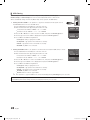
¦¦ Welcome Message
Welcome message is a feature to display custom message on TV, every time TV is turned on by Guest in Hotel room.
–– Welcome message settings are placed in Hotel Option Menu.
–– Welcome message should be ON in order to display the message on power on.
Hotel Mode
SI Vendor
ON
RJP Priority AV
1
Logo Download
Samsung
RJP Priority PC
2
Logo Display Time
...
RJP Priority HDMI
3
Power On Option
Last Option
Power On Channel
1
Channel Type
RJP AV Option
ATV
AV1
...
Auto Source
OFF
Energy Saving
Off
Power On Volume
10
RJP HDMI Option
HDMI1
Min Volume
0
Sub AMP Volume
6
Clone : TV to USB
Max Volume
100
Sub AMP Mode
2
Clone : USB to TV
Local Time
Manual
Pan Euro MHEG
OFF
Time Format
12 Hour
Cloning Data Reset
OFF
Failure
Welcome Message
3
Edit Welcome Message
2
DC Power Out
Panel Button Lock
Unlock
Power On Source
TV
Picture Menu Lock
OFF
PMOLED Test
Channel Editor
PMOLED Mormal Dim.
Music Mode AV
OFF
PMOLED Standby Dim.
Music Mode PC
OFF
Audio Loop In
OFF
Channel Auto Store
Music Mode Comp
OFF
Menu Display
ON
Dynamic SI
Music Mode Backlight
OFF
Hotel Logo
OFF
5V
OFF
–– Welcome message can be of 25 characters and it can be edited by changing its text in Hotel Service menu.
–– Following is the list of characters supported for Welcome message:
In letters from A to Z only in capital letters is allowed.
✎✎
–– Welcome message can be edited by using navigation, color & enter key of a Remote in “Edit Welcome Message” OSD.
Edit Welcome Message
W
E
L
R
C
H
O
O
M
T
E
E
T
L
O
O
U
_
A
B
C
D
E
F
G
H
I
J
K
L
M
N
O
P
Q
R
S
T
U
V
W
X
Y
Z
Move Left
Move Right
Black
Done
Move Enter
Return
–– Welcome message and hotel logo cannot be active at the same time.
26
English
LC452_453_457-hotel.indd 26
2010-04-12 오후 8:37:33
¦¦ Hotel Logo
Hotel Logo is a function that shows picture image which represents hotel during power on procedure.
–– Hotel Logo will be in hotel option menu in both Standalone and Interactive mode.
–– Lower menus will be enabled when hotel Logo option is on.
–– Hotel Logo will be displayed if there is logo image which is already stored in memory and hotel logo option is on during
power on procedure.
–– Hotel Logo will not be displayed when Hotel Logo option is off, even if the logo image exists.
Hotel Mode
SI Vendor
Power On Channel
Channel Type
Power On Volume
ON
RJP Priority AV
1
Logo Download
Samsung
RJP Priority PC
2
Logo Display Time
...
RJP Priority HDMI
3
Power On Option
Last Option
1
ATV
RJP AV Option
AV1
...
Auto Source
OFF
Energy Saving
Off
10
RJP HDMI Option
HDMI1
Min Volume
0
Sub AMP Volume
6
Clone : TV to USB
Max Volume
100
Sub AMP Mode
2
Clone : USB to TV
Local Time
Manual
Pan Euro MHEG
OFF
Time Format
12 Hour
Cloning Data Reset
OFF
Failure
Welcome Message
3
Edit Welcome Message
2
DC Power Out
Panel Button Lock
Unlock
Power On Source
TV
Picture Menu Lock
OFF
Channel Editor
PMOLED Test
PMOLED Mormal Dim.
Music Mode AV
OFF
PMOLED Standby Dim.
Music Mode PC
OFF
Audio Loop In
Music Mode Comp
OFF
Music Mode Backlight
OFF
OFF
Channel Auto Store
Menu Display
ON
Dynamic SI
Hotel Logo
OFF
5V
OFF
yy Hotel Logo
–– This option is to decide if hotel logo image will be displayed or not.
yy Hotel Logo DL
–– This option is to download logo image to memory.
–– Download the Logo File from PC to USB.
xx Logo File Format
––
––
––
––
––
––
–– Only bmp format is supported and the File name should be "samsung.bmp".
–– File size must be under 256Kbytes.
–– Maximum resolution is 960 x 540.
Connect the USB to TV and press Enter key.
“Wait” message will be displayed during copying image to TV.
“Completed” message will be displayed when the copy operation was finished successfully.
“Failed” message will be displayed when the copy operation was finished unsuccessfully.
“No USB” message will be displayed when any USB is not connected.
“No File” message will be displayed when there is no file to copy in USB.
yy Logo Display Time
–– This option is to decide Logo display time.
–– 3 sec / 5 sec / 7sec
English
LC452_453_457-hotel.indd 27
27
2010-04-12 오후 8:37:33
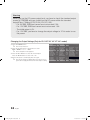
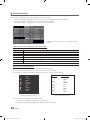
¦¦ USB Cloning
HDMI IN3
USB Cloning is a function to download user configured settings (Picture, Sound, Input,
Channel, Setup, and Hotel Setup) from one TV set and upload the same to other TV sets.
All the user-defined settings from the TV (Master Set) can be copied to the USB device.
yy Cloning from TV to USB: It is an operation to copy the stored data from the specific area on
the EEPROM from the TV set to the USB device.
1.Insert a USB drive into the USB port on the rear of the TV.
2.Enter the Interactive menu by pressing this buttons in order.
xx Interactive mode : INFO → MENU → 0 → 1 → EXIT
xx Standalone mode : MUTE → 1 → 1 → 9 → ENTER
Power On Option
Last Option
Auto Source
OFF
Energy Saving
Off
Clone : TV to USB
Clone : USB to TV
3.Press the ▲ or ▼ button to select “Clone:TV to USB”, then press the ENTERE button.
Pan Euro MHEG
OFF
Cloning Data Reset
OFF
4.The message “Clone:TV to USB” is displayed, then press the ENTERE button.
Welcome Message
5.You can Make sure USB cloning behavior.
Edit Welcome Message
xx In Progress: during copying data to USB.
xx Completed: copy operation was finished successfully.
xx Failed: copy operation was not finished successfully.
xx No USB: any USB is not connected.
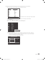
yy Cloning from USB to TV: It is an operation to download the stored data in USB device to TV set.
1.Insert a USB drive into the USB port on the rear of the TV.
2.Enter the Interactive menu by pressing this buttons in order.
xx Interactive mode : INFO → MENU → 0 → 1 → EXIT
xx Standalone mode : MUTE → 1 → 1 → 9 → ENTER
3.Press the ▲ or ▼ button to select “Clone:USB to TV”, then press the ENTERE button.
Power On Option
Last Option
Auto Source
OFF
Energy Saving
Off
Clone : TV to USB
Clone : USB to TV
Pan Euro MHEG
OFF
Cloning Data Reset
OFF
Welcome Message
Edit Welcome Message
4.The message “Clone:USB to TV” is displayed, then press the ENTERE button.
5.You can Make sure USB cloning behavior.
xx In Progress: during copying data to TV.
xx Completed: copy operation was finished successfully.
xx Failed: copy operation was not finished successfully.
xx No USB: any USB is not connected.
xx No File: there is no file to copy in USB.
✎✎ The operation to copy from USB to TV can be executed by pressing ENTERE key for 5 seconds.
For fast instant cloning during installation!
Insert USB key with master settings from first TV and press Enter key for 5 seconds.
28
English
LC452_453_457-hotel.indd 28
2010-04-12 오후 8:37:33
¦¦ Hotel Plug & Play
Hotel Plug & Play is a function that automatically performs the Hotel mode selection, Country Setup, Clock Setup and Picture
mode Setup once.
–– Hotel Plug & Play is available only one time when power is first turned ON.
–– After setting up first TV and Clone TV to USB
–– Next TV only needs to exit Hotel Plug & Play, connect USB, then Clone USB to TV.
yy UI Scenario
If Standalone Only is selected
Hotel Plug & Play
Easy Set Up
Interactive
Standalone Plug & Play
Standalone Only mode is set
If Interactive is selected
If Standalone Plug & Play
is selected
Interactive
Hotel Option Menu
Hotel Plug & Play
: English
Press Power OFF to exit.
Hotel Plug & Play
Select the OSD Language.
Menu Language
TV will enter the RF mode.
Standalone Only
Hotel Plug & Play
Antenna Source
Select Country.
r
Country
: United Kingdom
Enter
A
Previous
: Air r
Search
Enter
A
Previous
D
U
After Searching the channels.
Hotel Plug & Play
Hotel Plug & Play
Dynamic
Set the Clock Mode.
Standard
Clock Mode
A
Previous
U Move
Exit
Skip U Move
<Depending on Region, this step may not exist.>
Standalone
Hotel Option Menu
r
Channel Source: Digital & Analogue
Exit
A
Previous
: Auto
r
Skip
Exit
D
Press Power OFF
to exit.
English
LC452_453_457-hotel.indd 29
29
2010-04-12 오후 8:37:33
yy Hotel Plug & Play OSD
–– Initial Highlight: Interactive
–– If Standalone Only button is selected, the Standalone hotel mode is set by default and “Standalone mode is set” OSD is
displayed for 3 seconds.
–– TV enters into RF mode automatically after displaying “Standalone mode is set” OSD for 3 seconds.
–– When Interactive mode is selected, Interactive Setup Menu is displayed. Press power off button to exit from Interactive
menu.
–– When Standalone Plug & Play mode is selected, “Select Menu Language” OSD is displayed.
yy Select Menu Language OSD
–– When Standalone Plug & Play is selected from “Easy Set Up” OSD, “Select Menu Language” OSD is displayed.
–– Initial Highlight : English
–– Display time: OSD timeout and operation are the same as Samsung's consumer TV models.
–– If ENTER button is pressed, “Select Area” OSD is displayed.
yy Auto Search Mode OSD
–– If skip option is selected, it goes to Clock setting OSD.
–– If ENTER button is pressed, auto searching of channels is performed.
–– The OSD Display time, which is from the time that Auto Store is started to the time that Auto Sort is completed, is 30
seconds.
yy Clock setting OSD
–– Display time: 30 seconds.
–– The Clock Set item OSD is displayed
–– If ENTER button is pressed after setting the clock or in Auto, Picture Mode OSD is displayed.
yy Picture Mode OSD
–– Initial Highlight: Standard.
–– The Picture Mode OSD is displayed and the Dynamic or a Standard Picture mode can be selected.
–– After selecting the picture mode, it enters Standalone Setup Menu OSD, press power off to exit.
30
English
LC452_453_457-hotel.indd 30
2010-04-12 오후 8:37:33
¦¦ Multi Code Remocon
Multi Code Remocon is a special transmitter which is designed to control each TVs with one remote.
This function is useful where there is more than one TV in one location like hospital Set ID number will be displayed in source
osd. It is possible to support up to 10 different remote key transmission for multi code.
Initial ID code which each TV has is “0”.
–– ID code could be set and reset in Analog TV mode or PC mode. (not available in TTX channel or DTV channel)
–– ID code could be from 0 to 9.
–– Press Blue Key for over 3 seconds and the digit key a user wants to set.
–– Set ID OSD will be displayed in central position.
–– The following words will be displayed. “Remote control code is set to x. If you want to change Remote control code.
Enter the digit you want to change.” (x is the digit number) This OSD will be kept displaying until exit key is input.
Remote control code is set to 0. If you want to
change Remote control code, enter the digit you
want to change.
–– For example, TV and Remote will be set ID code #1 if user presses #1.
–– The following words will be displayed.“Remote control code is changed to 1” Then TV can be controlled by only remote
which has same ID code with TV’s.
–– If ID code does not match between remote and TV, the following words will be displayed. “ TV ID x”(x is the TV’s ID)
–– To reset ID code, press Yellow key for over 3 seconds. ID code of both TV and Remote will be reset to “0”. “Remote
control code is set to 0.” will be displayed.
¦¦ Setting the Time
OO MENU → Setup → Time → Clock → Clock Set
yy The time is entered
–– Press the remote control button to select Clock set and set up the time.
Clock
Clock Mode
: Manual
Clock Set yy Setting the Interactive Mode Time
–– If the Hotel System transmits time information, the time is set
automatically.
–– If the Hotel System does not transmit time information, the time cannot be
displayed.
►
U Move
E Enter
R Return
Clock Set
Day
u
Month
Year
01
d
01
2010
Hour
Minute
01
01
L Move
U Adjust
E Enter
R Return
✎✎ If the time is set, clock will be displayed on the front panel. (This function is available on the B457 model.)
English
LC452_453_457-hotel.indd 31
31
2010-04-12 오후 8:37:34
¦¦ Mixed Channel Map
Mixed Channel Map is a function to mix Air and Cable channels.
[ If there are no Cable channels, you can use this item as channel sorting. ]
–– Mixed channel Map, Channel Editor and Channel Auto Store are newly placed in Hotel Option Menu.
–– Mixed channel Map should be ON in order to mix Air and Cable channels.
–– Use Channel Editor to sort the channels as user-desired channel numbers.
Hotel Mode
ON
RJP Priority AV
1
Logo Download
...
SI Vendor
OFF
RJP Priority PC
2
Logo Display Time
...
3
Power On Option
Last Option
Power On Channel
1
Channel Type
ATV
RJP Priority HDMI
RJP AV Option
AV1
Power On Volume
10
RJP HDMI Option
Min Volume
0
Sub AMP Volume
Max Volume
100
Panel Button Lock
Unlock
Power On Source
TV
Picture Menu Lock
OFF
Channel Editor
Sub AMP Mode
Auto Source
HDMI1/DVI Energy Saving
6
Clone : TV to USB
OFF
Off
2
Clone : USB to TV
Local Time
Manual
Pan Euro MHEG
OFF
Time Format
12 Hour
Cloning Data Reset
OFF
Failure
Welcome Message
3
Edit Welcome Message
2
PMOLED Test
PMOLED Mormal Dim.
Music Mode AV
OFF
PMOLED Standby Dim.
DC Power Out
5V
Music Mode PC
OFF
Audio Loop In
OFF
Mixed Channel Map
ON
Music Mode Comp
OFF
Menu Display
ON
Channel Auto Store
Music Mode Backlight
OFF
Hotel Logo
OFF
Dynamic SI
OFF
<Depending on model and region, some menu items may
not exist>
Simple Steps for channel mixing under Stand-alone Mode
Step
Broad Outline
1
2
3
4
5
6
Turn on ‘Mixed Channel Map’ in Hotel Option Menu
Operate ‘Channel Auto Store’ in Hotel Option Menu (Antenna Source : Air + Cable)
Enter ‘Channel Editor’ in Hotel Option Menu
Compile a table related to the final channel lists you want to have
Rearrange channels with TOOLS Button based on the table you compiled
Press EXIT or RETURN Button to exit.
<For better comprehension, please refer to the following details>
Air & Cable Channels Mixing Manual
You can scan for Air and Cable channels by operating Channel Auto Store.
Automatically scanned channels may not have the user-desired channel numbers.
We suggest you compile a table related to the final channel lists you want to have like below.
1
A
1
2
A 2
A 3
4
A 4
70 900
BBC1
TF1(atv)
BBC2
FR1(atv)
FR2(atv)
Boxer
M6(atv)
Chnal+
Disney
<Scanned original Channel List>
Chnnel No.
A
A
A
A
1
2
3
4
5
6
7
8
9
Programme Name
BBC1
BBC2
FR1
BOXER
FR2
TF1
Disney
M6
Canal+
<User-desired Channel List>
Follow next steps to rearrange Air and Cable channels.
[To edit the channel numbers, enter ‘Stand-alone mode’ first.]
[Hotel Mode ‘ON’, Mixed Channel Map ‘ON’, Operate ‘Channel Auto Store’]
32
English
LC452_453_457-hotel.indd 32
2010-04-12 오후 8:37:34
1.Rearrange Air and Cable Channels based on User-desired Channel List in ‘Channel Editor’
a.Check the largest channel number from the user-desired channel list.
Chnnel No.
A
A
A
A
1
2
3
4
5
6
7
8
9
Programme Name
BBC1
BBC2
FR1
BOXER
FR2
TF1
Disney
M6
Canal+
← Programme 'Canal+' has the largest channel number
b.Locate cursor to a programme that you want to put it into the largest channel number.
c.Press TOOLS key.
d.Move cursor to Edit Channel Number and press ENTERE key.
1
A
1
2
A 2
A 3
4
A 4
70
900
BBC1
TF1(atv)
BBC2
FR1(atv)
FR2(atv)
Boxer
M6(atv)
Chnal+
Disney
Edit channel Number
Edit channel Name
e.Move the programme to the largest channel number by using up/down narrow keys or digit keys
xx ~ When you try to change it to an existing channel number, below message will be displayed.
"CH.XX has already been used. Change to Ch.XX?".
If you select 'yes', they'll be swapped with each other.
Edit Channel Number
Channel
Name
Canal+
u
9
d
0~9 Number
U Adjust
E Enter
R Return
English
LC452_453_457-hotel.indd 33
33
2010-04-12 오후 8:37:34
f. Check the second largest channel number from the user-desired channel list.
Chnnel No.
1
2
3
4
5
6
7
8
9
A
A
A
A
Programme Name
BBC1
BBC2
FR1
BOXER
FR2
TF1
Disney
M6
Canal+
← Programme 'M6' has the second largest channel number
g.Locate cursor to the other programme that you want to put it into the second largest channel number.
h.Press TOOLS key.
i. Move cursor to Edit Channel Number and press ENTERE key.
1
BBC1
A
1
2
A 2
A 3
4
A 4
9
900
TF1(atv)
BBC2
FR1(atv)
FR2(atv)
Boxer
M6(atv)
Chnal+
Disney
Edit channel Number
Edit channel Name
j. Move the programme to the second largest channel number by using up/down narrow keys or digit keys
Edit Channel Number
Channel
Name
M6
u
8
d
0~9 Number
U Adjust
E Enter
R Return
k.Do this process again for all the other programmes.
Now you can see the mixed channel list like below.
1
2
A 3
4
A
A
A
34
5
6
7
8
9
BBC1
BBC2
FR1
Boxer
FR2
TF1
Disney
M6
Canal+
English
LC452_453_457-hotel.indd 34
2010-04-12 오후 8:37:34
Installing the Wall Mount
Assembling the Blanking Bracket
When installing the TV onto a wall, attach the Blanking Bracket as shown.
Blanking Bracket
Installing the Wall Mount Kit
The wall mount kit (sold separately) allows you to mount the TV on the wall.
For detailed information on installing the wall mount, see the instructions provided with the wall mount. Contact a technician for
assistance when installing the wall mount bracket. Samsung Electronics is not responsible for any damage to the product or
injury to yourself or others if you select to install the TV on your own.
Wall Mount Kit Specifications (VESA)
✎✎
The wall mount kit is not supplied, but sold separately.
Install your wall mount on a solid wall perpendicular to the floor. When attaching to other building materials, please contact
your nearest dealer. If installed on a ceiling or slanted wall, it may fall and result in severe personal injury.
✎✎NOTE
xx Standard dimensions for wall mount kits are shown in the table below.
xx When purchasing our wall mount kit, a detailed installation manual and all parts necessary for assembly are provided.
xx Do not use screws that do not comply with the VESA standard screw specifications.
xx Do not use screws that are longer than the standard dimension or do not comply with the VESA standard screw
specifications. Screws that are too long may cause damage to the inside of the TV set.
xx For wall mounts that do not comply with the VESA standard screw specifications, the length of the screws may differ
depending on the wall mount specifications.
xx Do not fasten the screws too strongly; this may damage the product or cause the product to fall, leading to personal
injury. Samsung is not liable for these kinds of accidents.
xx Samsung is not liable for product damage or personal injury when a non-VESA or non-specified wall mount is used or
the consumer fails to follow the product installation instructions.
xx Our 57” and 63” models do not comply with VESA Specifications. Therefore, you should use our dedicated wall
mount kit for this model.
xx Do not mount the TV at more than a 15 degree tilt.
Product Family
inches
23~29
30~40
46~55
57~65
75 X 75
100 X 100
200 X 100
200 X 200
400 X 400
600 X 400
70~80
800 X 400
80~
1400 X 800
19~22
LCD-TV
VESA Spec. (A * B)
Standard Screw
Quantity
M4
M6
4
M8
Do not install your Wall Mount Kit while your TV is turned on. It may result in personal injury due to
electric shock.
English
LC452_453_457-hotel.indd 35
35
2010-04-12 오후 8:37:35
Securing the TV to the Wall
Caution: Pulling, pushing, or climbing on the TV may cause the TV to fall. In particular, ensure your children do
not hang over or destabilize the TV; doing so may cause the TV to tip over, causing serious injuries or death.
Follow all safety precautions provided on the included Safety Flyer. For added stability, install the anti-fall device
for safety purposes, as follows.
¦¦ To Avoid the TV from Falling
1.Put the screws into the clamps and firmly fasten them onto the wall.
Confirm that the screws have been firmly installed onto the wall.
✎✎ You may need additional material such as an anchor depending on
the type of wall.
✎✎ Since the necessary clamps, screws, and string are not supplied,
please purchase these additionally.
2.Remove the screws from the back center of the TV, put the screws into the
clamps, and then fasten the screws onto the TV again.
✎✎ Screws may not be supplied with the product. In this case, please
purchase the screws of the following specifications.
✎✎ Screw Specifications
xx For a 19 ~ 29 inch : M4
xx For a 30 ~ 40 inch : M6
xx For a 46 ~ 80 inch : M8
3.Connect the clamps fixed onto the TV and the clamps fixed onto the wall
with a strong cable and then tie the string tightly.
✎✎ NOTE
Wall
xx Install the TV near to the wall so that it does not fall backwards.
xx It is safe to connect the string so that the clamps fixed on the
wall are equal to or lower than the clamps fixed on the TV.
xx Untie the string before moving the TV.
4.Verify all connections are properly secured. Periodically check connections
for any sign of fatigue for failure. If you have any doubt about the security of
your connections, contact a professional installer.
Assembling the Cables
Enclose the cables in the Cable tie so that the cables are not visible through
the transparent stand. Overly rigid or thick cables can damage input jacks for
long term usage.
36
< Cable Tie >
English
LC452_453_457-hotel.indd 36
2010-04-12 오후 8:37:35
Anti-theft Kensington Lock
The Kensington Lock is not supplied by Samsung. It is a device used to
physically fix the system when using it in a public place. The appearance and
locking method may differ from the illustration depending on the manufacturer.
Refer to the manual provided with the Kensington Lock for additional
information on proper use.
1
2
✎✎Please find a “K” icon on the rear of the TV. A kensington slot is beside
the “K” icon.
1.Insert the locking device into the Kensington slot 1 on the LCD TV and
turn it as shown 2.
3
<Optional>
2.Connect the Kensington Lock cable 3.
3.Fix the Kensington Lock to a desk or a heavy stationary object.
✎✎The locking device has to be purchased separately.
✎✎The location of the Kensington slot may be different depending on the TV model.
Specifications
Items
TV System
Data
19inch / 22inch : 3W x 2
26inch : 5W x 2
32inch / 37inch / 40inch : 10W x 2
Audio out
Input
Comment
PAL, SECAM, DVB-T/C
Speaker out
DC out
Specification
Variable Audio
4W mono 8 ohm SPK'
RCA Jack output
BTL Sound output
Audio out
500mVrms
Phone Jack, Monitor out
5V out
Max 2.5A
Initial output Voltage
12V out
Max 1.5A
Change output voltage
Component
Y, Pb, Pr, Audio-L/R
PC
D-sub, Audio-L/R
A/V
Audio Video Jack
EXT
Scart Jack
HDMI
Compatible with the HDMI
Specifications
Antenna
75 ohm Unbalanced, Din Jack
DATA
RJ-12
RJP
RS232
Operating temperature
10°C ~ 40°C (50°F ~ 104°F)
Operating Humidity
10% ~ 80%
Storage Temperature
-20°C ~ 45°C (-4°F ~ 113°F)
Storage Humidity
5% ~ 95%
VHF/UHF/CATV
Jack Pack Only, TeleAdapt RJP Only
non-condensing
non-condensing
✎✎Design and specifications are subject to change without prior notice.
✎✎For information about power supply, and more about power consumption, refer to the label attached to the product.
English
LC452_453_457-hotel.indd 37
37
2010-04-12 오후 8:37:35
Contact SAMSUNG WORLDWIDE
If you have any questions or comments relating to Samsung products, please contact the SAMSUNG customer care center.
Country
Customer Care Centre
AUSTRIA
800-112233
FINLAND
0771-400002
FRANCE
0825-022062
GERMANY
01805-471101
HUNGARY
0640-985985
ITALIA
800-194194
NETHERLANDS
015-2197000
POLAND
0-801-B2BSAM (222726)
PORTUGAL
808-B2BSAM
SPAIN
0902024-010
UNITED KINGDOM
+44 (0) 845 8414141
SOUTH AFRICA
0860-SAMSUNG (726-7864)
U.A.E
800-SAMSUNG (726-7864)
8000-4726
© 2010 Samsung Electronics Co., Ltd. All rights reserved.
LC452_453_457-hotel.indd 38
2010-04-12 오후 8:37:35