1
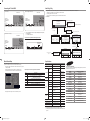
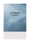
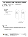
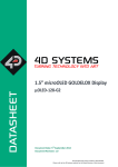
Quick Setup Guide
To register this product please visit
www.samsung.com/register.
Installing the LED TV Stand
Installing the Wall Mount Kit
Wall Mount Kit Specifications (VESA)
See separate guide for installing the stand.
Wall mount items (sold
separately) allow you to mount
the TV on a wall. For detailed
information on installing the
wall mount, see the instructions
provided with the Wall Mount
Blanking Bracket
1
items. Contact a technician for
assistance when installing the
2
wall mounted bracket. Samsung Electronics is not responsible for any damage
to the product or injury to yourself or others if you select to install the TV on your
own.
Install your wall mount on a solid wall perpendicular to the floor. When attaching
to other building materials, please contact your nearest dealer. If installed on a
ceiling or slanted wall, it may fall and result in severe personal injury.
➣➣ Standard dimensions for wall mount kits are shown in the table below.
➣➣ When purchasing our wall mount kit, a detailed installation manual and all
parts necessary for assembly are provided.
➣➣ Do not use screws that do not comply with the VESA standard screw
specifications.
➣➣ Do not use screws that are longer than the standard dimension or do not
comply with the VESA standard screw specifications. Screws that are too
long may cause damage to the inside of the TV set.
➣➣ For wall mounts that do not comply with the VESA standard screw
specifications, the length of the screws may differ depending on the wall
mount specifications.
➣➣ Do not fasten the screws too strongly; this may damage the product or
cause the product to fall, leading to personal injury. Samsung is not liable
for these kinds of accidents.
➣➣ Samsung is not liable for product damage or personal injury when a nonVESA or non-specified wall mount is used or the consumer fails to follow
the product installation instructions.
➣➣ Our 57” and 63” models do not comply with VESA Specifications. Therefore,
you should use our dedicated wall mount kit for this model.
➣➣ Do not mount the TV at more than a 15 degree tilt.
➣➣ Always use two people to mount the TV to a wall.
s
s
s
Stand (1EA)
List of Parts
1
(A)
5EA (M4 X L12)
(B)
5EA (M4 X L8)
s
s
Guide Stand (1EA)
Screws (10EA)
Follow the steps below to connect the TV to the stand.
2
3
4
Screws (M4 X L12)
➣➣ Remove the stand and cover the bottom hole with the cover.
Top view
(M4xL8)
s
2
Guide Stand
5
6
7
s
s
s
s
s
s
s
Stand
s
s
4
s
s
s
s
s
5
1
1
3
5
7
Rear
Remote Control & Batteries (AAA x 2) 2 Power Cord
Cleaning Cloth
4 Blanking Bracket
Data Cable (BN39-00865B, BN39-01011B) 6 Stand & Screw (M4xL16)
Warranty Card / Safety Guide (Not available in some locations)
1
3
2
4
3
1.
5
2.
Connect the Guide Stand
to the Stand using four
screws (M4 X L12) as
shown.
With your TV upright,
connect the TV to the
Stand as shown.
3.
✎✎NOTE
Fasten two screws (M4
X L8) at position 1, and
then fasten three screws
(M4 X L8) at position 2.
@
!
0
9
8
7
6
4
1
1
xx Make sure to distinguish between the front and back of the Stand and Guide
2
7
6
8
9
0
1 Holder-Wire Stand
2 Cable Tie
3 Holder-Wire (3EA)
4 Holder-Ring (4EA)
5 Power Cord Clamp
6 Component Adapter
7 AV Adapter
8 Audio Adapter
9 AV Adapter
(Aus, Singapore, NZ only)
(Aus, Singapore, NZ only)
0 SCART Adapter
(EU, Mideast Africa only)
Stand when assembling them.
Product
Family
2
xx Make sure that at least two persons lift and move the LED TV.
with the
xx Stand the product up and fasten the screws. If you fasten the screws
3
LED TV
[Ultra-Slim]
LED TV placed down, it may lean to one side.
$
inches
VESA Spec.
(A * B)
Standard
Screw
19 ~ 22
75 X 75
M4
23 ~ 29
200 X 100
32~37
200 X 200
40~55
400 X 400
56~65
600 X 400
M8
Quantity
4
%
Do not install your Wall Mount Kit while your TV is turned on.
It may result in personal injury due to electric shock.
4
4
5
5
Viewing the Connection Panel
BN68-02879E-X0
@
!
0
9
8
7
6
4
@
!
0
8
9
7
6
4
1 RJP
EU Hotel (4000)
1
Aus, NZ, Singapore Hotel (4000)
Mideast Africa Hotel (4000)
2
1
1
2
2
#
4
$
$
%
%
Power Input
4
5
3 COMMON INTERFACE
4 HDMI IN 1(DVI), 2
3
Power Input
2 USB (HDD) / CLONING
5 PC / DVI AUDIO IN
6 PC IN
7 COMPONENT IN
8 AV IN
Power Input
5
4
9 EXT(RGB)
5
0 ANT IN
! DATA
-- Used to support data communication between the TV and the SBB.
@
!
0
9
8
7
6
4
@
!
9
0
8
7
6
@
4
1
1
2
2
!
0
8
7
7
6
4
@ Power input
# AV OUT
-- AUDIO OUT
-- VIDEO OUT
(DTV signal is unsupportable. This output is only for Analogue video signal.)
$ Headphones jack
#
% HP-ID
$
$
%
%
4
4
5
5
@
@
!
0
9
8
7
6
!
0
8
7
7
6
4
4
1
[QSG]BN68-02879E-Hotel.indd 1
2
2010-04-13 오전 10:04:33
Connecting the TV with SBB
Hotel Plug & Play
Hotel Plug & Play is a function that automatically performs the Hotel mode selection, Country Setup, Clock Setup and Picture mode Setup once.
EU Hotel (4000)
Aus, NZ, Singapore Hotel (4000)
TV Rear Panel
ETH MODEM
TV Rear Panel
- Hotel Plug & Play is available only one time when power is first turned ON.
- After setting up first TV and Clone TV to USB
- Next TV only needs to exit Hotel Plug & Play, connect USB, then Clone USB to TV.
♦♦
UI Scenario
Hotel Server
STB(Set Top Box) or
SBB (Set Back Box)
Hotel Server
STB(Set Top Box)
or SBB (Set Back
Box)
If Standalone Only is selected
Hotel Plug & Play
Easy Set Up
ETH MODEM
ETH MODEM
Interactive
Standalone Plug & Play
Standalone Only mode is set
Data Cable
Data Cable
If Interactive is selected
If Standalone Plug & Play
is selected
Mideast Africa Hotel (4000)
TV Rear Panel
1. Connect the [DATA] jack of the TV to the [ETH MODEM] jack of the STB (SBB)
with the Data cable.
➣➣ Use data communication.
♦♦
Hotel Server
STB(Set Top Box)
or SBB(Set Back
Box)
Interactive
Hotel Option Menu
Hotel Plug & Play
Menu Language
Refer to the code label on the data cables.
: English
Press Power OFF to exit.
Hotel Plug & Play
Select the OSD Language.
List of Vendors for Compatible Data Cables Supplied with the TV
TV will enter the RF mode.
Standalone Only
Hotel Plug & Play
Antenna Source
Select Country.
r
Country
: United Kingdom
Enter
Confirm the code on
the Code Label
A
Previous
r
A
Previous
Hotel Plug & Play
Standalone
Hotel Option Menu
D
Skip U Move
Hotel Plug & Play
Dynamic
Set the Clock Mode.
Standard
Clock Mode
A
Previous
U Move
Exit
U
After Searching
the channels.
ETH MODEM
Press Power OFF
to exit.
r
Search
Enter
<Depending on Region, this step may not exist.>
Data Cable
: Air Channel Source: Digital & Analogue
Exit
A
Previous
: Auto
r
Skip
Exit
D
ETH MODEM
Mixed Channel Map
Specifications
Mixed Channel Map is a function to mix Air and Cable channels.
Items
[ If there are no Cable channels, you can use this item as channel sorting. ]
- Mixed channel Map, Channel Editor and Channel Auto Store are newly placed
in Hotel Option Menu.
- Mixed channel Map should be ON in order to mix Air and Cable channels.
- Use Channel Editor to sort the channels as user-desired channel numbers.
Hotel Mode
ON
RJP Priority AV
1
Logo Download
...
SI Vendor
OFF
RJP Priority PC
2
Logo Display Time
...
3
Power On Option
Last Option
Power On Channel
Channel Type
ETH MODEM
Power On Volume
1
ATV
RJP AV Option
AV1
Auto Source
RJP HDMI Option
Min Volume
0
Sub AMP Volume
6
Clone : TV to USB
Max Volume
100
Sub AMP Mode
2
Clone : USB to TV
HDMI1/DVI Energy Saving
OFF
Unlock
Local Time
Manual
Pan Euro MHEG
OFF
Power On Source
TV
Time Format
12 Hour
Cloning Data Reset
OFF
OFF
PMOLED Test
Failure
Welcome Message
Picture Menu Lock
PMOLED Mormal Dim.
3
Edit Welcome Message
2
Music Mode AV
OFF
PMOLED Standby Dim.
DC Power Out
5V
Music Mode PC
OFF
Audio Loop In
OFF
Mixed Channel Map
ON
Music Mode Comp
OFF
Menu Display
ON
Channel Auto Store
OFF
Hotel Logo
OFF
Dynamic SI
Music Mode Backlight
ETH MODEM
OFF
Speaker out
Simple Steps for channel mixing under Stand-alone Mode
Step
Broad Outline
1
Turn on ‘Mixed Channel Map’ in Hotel Option Menu
2
Operate ‘Channel Auto Store’ in Hotel Option Menu
(Antenna Source : Air + Cable)
Off
Panel Button Lock
Channel Editor
RJP Priority HDMI
10
TV System
3
Enter ‘Channel Editor’ in Hotel Option Menu
4
Compile a table related to the final channel lists you want to have
5
Rearrange channels with TOOLS Button based on the table you compiled
6
Audio out
DC out
Input
<Depending on model and region, some menu items may not exist>
Data
Comment
Contact SAMSUNG WORLDWIDE
26inch : 5W x 2
If you have any questions or comments relating to Samsung products, please contact
the SAMSUNG customer care center.
32inch : 10W x 2
Audio out Variable Audio 4W X 1, 8 ohm SPK’
Press EXIT or RETURN Button to exit.
<For better comprehension, please refer to the following details>
Specification
ATSC / NTSC3.58
500mVrms
RCA Jack output
OTL Sound output
Phone Jack, Monitor
out
Change output
voltage
12V out
Max 1.5A
Component
Y, Pb, Pr, Audio-L/R
PC
D-sub, Audio-L/R
A/V
Audio Video Jack
EXT
Scart Jack
(EU, Mideast Africa Only)
HDMI
Compatible with the HDMI
Specifications
DVI is Supported
Antenna
75 ohm Unbalanced, Din Jack
VHF/UHF/CATV
DATA
RJ-12
Ex-Link
RS232
Operating temperature
50°F ~ 104°F(10°C ~ 40°C)
Operating Humidity
10% ~ 80%
Storage Temperature
-4°F ~ 113°F(-20°C ~ 45°C )
Storage Humidity
5% ~ 95%
Jack Pack Only,
TeleAdapt RJP Only
non-condensing
Country
Customer Care Centre
AUSTRIA
800-112233
FINLAND
0771-400002
FRANCE
0825-022062
GERMANY
01805-471101
HUNGARY
0640-985985
ITALIA
800-194194
NETHERLANDS
015-2197000
POLAND
0-801-B2BSAM (222726)
PORTUGAL
808-B2BSAM
SPAIN
0902024-010
UNITED KINGDOM
+44 (0) 845 8414141
SOUTH AFRICA
0860-SAMSUNG(726-7864)
U.A.E
800-SAMSUNG (726-7864)
8000-4726
AUSTRALIA
1300 362 603
NEW ZEALAND
0800 SAMSUNG (726-786)
SINGAPORE
1800-SAMSUNG (726-7864)
non-condensing
➣➣ Design and specifications are subject to change without prior notice.
➣➣ For the power supply and Power Consumption, refer to the label attached to the
product.
[QSG]BN68-02879E-Hotel.indd 2
2010-04-13 오전 10:04:35