1
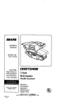
Owner's Manual
II:RRFTSMRN I
76 mm (3 in.) DUSTLESS
BELT SANDER
Double Insulated
Stock No.
925222
Model No.
315.252220
Save this manual for
future reference
_,
CAUTION:
Read and follow
all Safety Rules and Operating
Instructions before first use of
• Safety
• Features
this product.
•
•
•
•
Customer Help Line:
1-877-369-8665
Sold by: Sears
Visit the Craftsman
972000-537
8-98
Canada
Inc.,
Toronto
Adjustments
Operation
Maintenance
Parts List
M5B 2B8
web page: www.sears.com/craftsman
Printed in USA
•
TableOfContents.........................................................................................................................................
2
•
WarrantyandIntroduction
..............................................................................................................................
2
•
•
•
RulesForSafeOperation...........................................................................................................................
3-5
ProductSpecifications,
Unpacking,
andAccessories
....................................................................................
5
Features.....................................................................................................................................................
6
•
•
•
Adjustments
.................................................................................................................................................
7-9
Operation
.................................................................................................................................................
10-11
Maintenance
............................................................................................................................................
12-15
•
•
Exploded
ViewandRepairPartsList......................................................................................................
16-17
PartsOrdering/ Service ...............................................................................................................................
18
FULL TWO YEAR WARRANTY
ON CRAFTSMAN
TOOL
If this rRRFTSMRN Tool fails to operate within two years from the date of purchase, return it to the nearest
Sears Canada Inc. ("Sears") store and "Sears" will repair it, free of charge.
If this tool is used for commercial or rental purposes, this warranty applies for only 90 days from the date of
purchase.
This warranty is in addition to any statutory warranty.
Sears, Canada Inc., Toronto M5B 2B8
Your belt sander has many features for making
sanding operations more pleasant and enjoyable.
Safety, performance and dependability have been
given top priority in the design of this sander making it
easy to maintain and operate.
_lb CAUTION:
Carefully read through this entire
owner's manual before using your new belt
sander. Pay close attention to the Rules For Safe
Operation, Warnings and Cautions. If you use
your belt sander properly and only for what it is
intended, you will enjoy years of safe, reliable
service.
GENERAL
Your Craftsman Belt Sander is suitable for coarse, medium and fine sanding of wood, metals, plastics, and other
materials, tt is ideal when used for smoothing rough boards, chamfering, rounding edges and many other
general sanding applications. It is also an excellent tool for removing paint, varnishes, and stains. Its balanced
design makes it easy to use.
Look for this symbol
safety is involved.
to point
out important
safety
precautions.
It means
attention!!!
Your
The purpose of safety symbols is to attract your attention to possible dangers. The safety symbols, and
the explanations with them, deserve your careful attention and understanding. The safety warnings do
not by themselves eliminate any danger. The instructions or warnings they give are not substitutes for
proper accident prevention measures.
SYMBOL
A
MEANING
SAFETY
ALERT
SYMBOL:
Indicates danger, warning, or caution. May be used in conjunction with other symbols or pictographs.
A
DANGER: Failure to obey a safety warning will result in serious injury to yourself or to others.
Always follow the safety precautions to reduce the risk of fire, electric shock and personal injury.
A
WARNING:
Failure to obey a safety warning can result in serious injury to yourself or to others.
Always follow the safety precautions to reduce the risk of fire, electric shock and personal injury.
A
CAUTION:
Failure to obey a safety warning may result in property damage or personal injury to
yourself or to others. Always follow the safety precautions to reduce the risk of fire, electric shock and
personal injury.
NOTE:
DOUBLE
Advises you of information or instructions vital to the operation or maintenance of the equipment.
INSULATION
IMPORTANT
Double insulation is a concept in safety, in electric
power tools which eliminates the need for the usual
three-wire grounded power cord. All exposed metal
parts are isolated from internal metal motor
components with protecting insulation. Double
insulated tools do not need to be grounded.
Servicing of a tool with double insulation requires
extreme care and knowledge of the system and
should be performed only by a qualified service
technician. For service we suggest you return the tool
to your nearest Sears Store for repair. Always use
original factory replacement parts when servicing.
,_
•
WARNING:
Do not attempt to operate this tool
until you have read thoroughly and understand
completely all instructions, safety rules, etc.
contained in this manual. Failure to comply can
result in accidents involving fire, electric shock,
or serious personal injury. Save owner's manual
and review frequently for continuing safe
operation, and instructing others who may use
this tool.
READ ALL INSTRUCTIONS
KNOW YOUR POWER TOOL. Read owner's
AVOID DANGEROUS
ENVIRONMENT.
Don't
use power tools in damp or wet locations or
expose to rain. Keep work area well lit.
•
KEEP CHILDREN AND VISITORS AWAY. All
visitors should wear safety glasses and be kept a
safe distance from work area. Do not let visitors
contact tool or extension cord.
STORE IDLE TOOLS. When not in use, tools
should be stored in a dry and high or locked-up
place - out of the reach of children.
manual carefully. Learn its applications and
limitations as well as the specific potential
hazards related to this tool.
DON'T FORCE TOOL. tt will do the job better
and safer at the rate for which it was designed.
•
GUARD AGAINST ELECTRICAL SHOCK BY
PREVENTING BODY CONTACT WITH
GROUNDED SURFACES. For example; pipes,
radiators, ranges, refrigerator enclosures.
attachment to do the job of a heavy duty tool.
Don't use tool for purpose not intended - for
example - A circular saw should never be used
for cutting tree limbs or logs.
•
KEEP GUARDS IN PLACE AND IN WORKING
ORDER.
WEAR PROPER APPAREL.
•
KEEP WORK AREA CLEAN. Cluttered areas
and benches invite accidents.
USE RIGHT TOOL. Don't force small tool or
Do not wear loose
clothing or jewelry that can get caught in tool's
moving parts and cause personal injury. Rubber
gloves and nonskid footwear are recommended
RULES
FOR SAFE OPERATION
(Continued)
when working outdoors. Wear protective hair
covering to contain long hair and keep it from
being drawn into nearby air vents.
cords are marked with the suffix W-A, for example - SJTW-A or SJOW-A.
ALWAYS WEAR SAFETY GLASSES. Everyday
eyeglasses have only impact-resistant lenses;
they are not safety glasses.
FOR WET SANDING. Failure to comply can
result in electrical shock causing serious injury or
worse.
PROTECT YOUR LUNGS. Wear a face or dust
KEEP HANDS AWAY FROM SANDING AREA.
mask if the operation is dusty.
PROTECT YOUR HEARING. Wear hearing
protection during extended periods of operation.
DON'T ABUSE CORD. Never carry tool by cord
or yank it to disconnect from receptacle. Keep
cord from heat, oil, and sharp edges.
SECURE WORK. Use clamps or a vise to hold
work. It's safer than using your hand and it frees
both hands to operate tool.
DON'T OVERREACH. Keep proper footing and
balance at all times. Do not use while standing
on a ladder or unstable support. Secure tools
when working at elevated positions.
MAINTAIN TOOLS WITH CARE. Keep tools
sharp and clean for best and safest performance.
Follow instructions for lubricating and changing
accessories.
DISCONNECT TOOLS. When not in use, before
servicing, or when changing or adjusting sanding
belt, attachments, blades, bits, cutters, etc., all
tools should be disconnected from power supply.
REMOVE ADJUSTING
KEYS AND
WRENCHES. Form habit of checking to see that
keys and adjusting wrenches are removed from
tool before turning it on.
AVOID ACCIDENTAL STARTING. Don't carry
plugged-in tool with finger on switch. Be sure
switch is offwhen plugging in.
MAKE SURE YOUR EXTENSION CORD IS IN
GOOD CONDITION. When using an extension
cord, be sure to use one heavy enough to carry
the current your product will draw. An undersized
cord will cause a drop in line voltage resulting in
loss of power and overheating. A wire gage size
(A.W.G.) of at least 14 is recommended for an
extension cord 100 feet or less in length. A cord
exceeding 100 feet is not recommended. If in
doubt, use the next heavier gage. The smaller
the gage number, the heavier the cord.
OUTDOOR
USE EXTENSION CORDS. When
tool is used outdoors, use only extension cords
suitable for use outdoors. Outdoor approved
NEVER USE THIS OR ANY POWER SANDER
NEVER USE IN AN EXPLOSIVE
ATMO-
SPHERE. Normal sparking of the motor could
ignite fumes.
INSPECT TOOL CORDS PERIODICALLY
and if
damaged, have repaired at your nearest Sears
Repair Center. Stay constantly aware of cord
location and keep it well away from the sanding
area.
INSPECT EXTENSION CORDS PERIODICALLY and replace if damaged.
KEEP HANDLES DRY, CLEAN, AND FREE
FROM OIL AND GREASE. Always use a clean
cloth when cleaning. Never use brake fluids,
gasoline, petroleum-based products, or any
strong solvents to clean your tool.
STAY ALERT AND EXERCISE CONTROL.
Watch what you are doing and use common
sense. Do not operate tool when you are tired.
Do not rush.
CHECK DAMAGED PARTS. Before further use
of the tool, a guard or other part that is damaged
should be carefully checked to determine that it
will operate properly and perform its intended
function. Check for alignment of moving parts,
binding of moving parts, breakage of parts,
mounting and any other conditions that may
affect its operation. A guard or other part that is
damaged should be properly repaired or replaced by an authorized service center.
DO NOT USE TOOL IF SWITCH DOES NOT
TURN IT ON AND OFF. Have defective switches
replaced by an authorized service center.
INSPECT FOR and remove all nails from lumber
before sanding.
DO NOT operate this tool while under the
influence of drugs, alcohol, or any medication.
DO NOT USE THIS SANDER FOR OVERHEAD
SANDING. Overhead sanding could result in
dropping sander or loss of control. These situations could result in an accident resulting in
possible serious injury.
RULES
FOR SAFE OPERATION
(Continued)
POLARIZED PLUGS. To reduce the risk of
WHEN SERVICING USE ONLY IDENTICAL
CRAFTSMAN REPLACEMENT PARTS.
electric shock, this tool has a polarized plug (one
blade is wider than the other). This plug will fit in
a polarized outlet only one way. If the plug does
not fit fully in the outlet, reverse the plug. If it still
does not fit, contact a qualified electrician to
install the proper outlet. Do not change the plug
in any way.
SAVE THESE INSTRUCTIONS.
Refer to them
frequently and use them to instruct others who
may use this tool. If you loan someone this tool,
loan them these instructions also.
_I, WARNING:
The operation of any belt sander can result in foreign objects being thrown into your eyes,
which can result in severe eye damage. Before beginning power tool operation, always wear
safety goggles or safety glasses with side shields and a full face shield when needed. We
recommend Wide Vision Safety Mask for use over eyeglasses or standard safety glasses
with side shields, available at Sears Retail Stores.
SAVE THESE INSTRUCTIONS
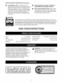
Input
7.5 Amperes
Sanding Surface
123 square cm (19 square in.)
Rating
120 volts, 60 Hz, AC
Overall Length
305 mm (12 in.)
No Load Speed
1300 surface ft./min.
Net Weight
4.5 kg. (10 Ibs.)
Belt Size
76 mm x 533 mm (3 in. x 21 in.)
Your belt sander has been shipped completely
assembled except for the sanding belt and dust bag.
Inspect it carefully to make sure no breakage or
damage has occurred during shipping. If any parts are
damaged or missing, contact your nearest Sears
Retail Store to obtain replacement parts before
attempting to operate sander. Loose parts in carton
will be dust bag and this owner's manual.
FOR
A
COMPLETE
SELECTION
OF|
ii
ACCESSORIES
FOR THIS AND
CRAFTSMAN
POWER AND BENCH
OTHER|
TOOLS,|
VISIT YOUR NEAREST SEARS RETAIL STORE.J
_ib
WARNING:
If any parts are missing, do not
operate this tool until the missing parts are
replaced. Failure to do so could result in possible
serious personal injury.
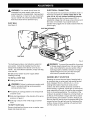
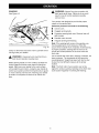
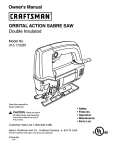
KNOW YOUR BELT SANDER
trigger, push in the lock button located on the side of
the handle, then while holding the lock button pushed
in, release the trigger. To release the lock, depress
the trigger and release.
See Figure 1.
Before attempting to use any tool, familiarize yourself
with all operating features and safety requirements.
DUST
Features include easily operated lock-on button, and
a dust bag for dustless sanding.
BAG
SWITCH
A dust bag is included with your sander to allow
dustless sanding. Its use will help keep the work area
clean.
To turn your sander ON, depress the switch trigger.
Release switch trigger to turn your sander OFF.
POWER
LOCK-
CORD
An extra long power cord that stays soft and flexible in
cold weather has been provided on your sander. The
plug design is shaped so that it won't snag on your
work during use. A molded cord clip on the plug
makes cord storage easier.
ON BUTTON
The switch of your sander is equipped with a lock-on
feature which is convenient when operating for
extended periods of time. To lock-on, depress the
FRONT
HANDLE
TRACKING
SCREW
DUSTBAG
DRIVE
ROLLERASSEMBLY
TENSION
RELEASELEVER
LOCK-ON
BUTTON
REAR
HANDLE
SANDING
BELT
FRONT
IDLERROLLER
MOLDED
CORDCLIP
SWITCH
TRIGGER
POWERCORD
Fig. 1
_
WARNING:
Do not allow familiarity with your sander to make you careless. Remember that a careless
fraction of a second is sufficient to inflict severe injury.
6
,_.
n
WARNING:
Your sander should never be
connected to a power supply when you are
assembling parts, changing belts, making adjustments, cleaning, or when not in use. Disconnecting your sander will prevent accidental starting
that could cause serious personal injury.
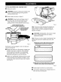
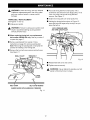
DUST BAG
See Figure 2.
ELECTRICAL
CONNECTION
Your belt sander has a precision built electric motor. It
should be connected to a power supply that is 120
volts, 60 Hz, AC only (normal household current).
Do not operate this tool on direct current (DC). A
substantial voltage drop will cause a loss of power and
the motor will overheat. If your sander does not
operate when plugged into an outlet, double-check the
power supply.
DUSTBAG RETAINER
COVER
DUSTBAG
Fig. 2
The dust bag provides a dust collection system for
your sander. It should be installed over the dust
exhaust hole located on the blower cover of your
sander. For more efficient operation, empty dust bag
when half full.
Do not connect sander to power supply before
installing dust bag.
_
Unplug your sander.
WARNING:
Failure to unplug your sander could
result in accidental starting causing possible
serious personal injury.
•
Fit opening in dust bag retainer over exhaust hole
on blower cover.
•
Slide dust bag retainer in the direction of the arrow
as shown in figure 2.
•
Dust bag is secure when it fits snugly on blower
cover.
TO EMPTY DUST BAG
Remove
7ipper
dust
and
bag
shake
from
blower
out dust.
WARNING:
To prevent the possibility of sawdust
or foreign objects being thrown into your face and
eyes, never attempt to use your sander without
dust bag properly installed. Sawdust or foreign
objects being thrown into your face and eyes
could result in possible serious injury.
SANDING
TO INSTALL DUST BAG
•
,_
cover
on sander,
open
BELT
SELECTION
Selecting the correct size and type of sanding belt is
an important step in achieving a high quality sanded
finish. Standard 76 mm x 533 mm (3 in. x 21 in.)
sanding belts made of aluminum oxide, silicon
carbide, and other synthetic abrasives are best for
power sanding. In general, coarse grit will remove the
most material and fine grit will produce the smoothest
finish in all sanding operations. The condition of the
surface to be sanded will determine which grit belt will
do the job. If the surface is rough, start with a coarse
grit belt sanding until surface is uniform. Medium grit
belt may then be used to remove scratches left by the
coarser belt and fine grit belt used for finishing of the
surface. Always continue sanding with each grit belt
until the surface is uniform.
INSTALLING/REMOVING
•
,_
•
SANDING
BELT
Unplug your sander.
WARNING:
Failure to unplug your sander could
result in accidental starting causing possible
serious personal injury.
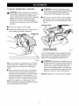
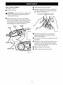
Position sander as shown in figure 3.
d_L WARNING:
Keep hands and fingers clear of
front idler roller and spring mechanism at all
times. Failure to do so could result in them
getting pinched, causing possible serious injury.
Fig. 4
LOWERTENSIONRELEASE
LEVERTOSECURESANDINGBELT
TENSION
RELEASELEVER
G BELT
LIFTTENSIONRELEASE
LEVERTO REMOVE
SANDINGBELT
Note: The arrow inside sanding belt indicates the
belt's direction of rotation, while the direction of
rotation of the drive roller indicates the sander's
direction of rotation.
'_of
CAUTION:
Sanding belts, with an arrow inside
belt, installed backwards can create a
hazardous condition.
Note: If there is no arrow inside of sanding belt, then
sanding belt cannot be installed backwards. See
Figure 5.
SANDINGBELTS WITHDIRECTIONOF ROTATION
ARROWSMUSTBE INSTALLEDCORRECTLY
Fig. 3
Belt tension must be released in order to install and
remove sanding belt:
•
Release belt tension by lifting tension release lever
straight up as shown in figure 3. When sufficient
force is exerted, the spring will be compressed
allowing the roller to lock in a rear position. This
flees the sanding belt so it can be removed.
•
Install a new sanding belt making sure arrow inside
of belt is pointing in the direction of rotation, which
is clockwise when looking into open side of sander.
See Figure 4.
SANDINGBELTSWITHOUTDIRECTIONOF ROTATION
ARROWSCAN BE USEDIN EITHERDIRECTION
Fig. 5
•
Roughly align the belt to its correct position.
•
Lower tension release lever to release tension on
roller and secure sanding belt.
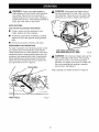
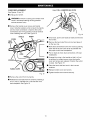
TO ADJUST
_
SANDING
BELT TRACKING
,_
WARNING:
Before connecting your sander to
power supply, always check to be sure it is not in
lock-on position (depress and release switch
trigger). Failure to do so could result in accidental
starting of your sander resulting in possible
serious injury. Also, do not lock the trigger on
jobs where your sander may need to be stopped
suddenly.
•
WARNING:
If sanding belt begins to wear
excessively on the inner edge, readjust tracking
screw. It is adjusted too far inward and the
sanding belt is rubbing against internal parts.
When you are sure the belt will not rub against
internal parts, start your sander and fine adjust
the tracking screw until the belt stabilizes. See
Figure 7.
TRACKINGSCREW
•
Connect your sander to power supply.
•
With sander positioned as shown in figure 6, pull
switch trigger and release immediately.
SANDINGBELT
TURNTRACKINGSCREW
TO ADJUSTSANDINGBELT
Fig. 7
When correctly adjusted, the outer edge of the belt
will be even with the outer edge of the base of your
sander. Belt life will be greatly increased if a few
seconds are spent adjusting the belt tracking.
Fig. 6
Note: This position is for adjustments only. Sanding
belt should not be in contact with workpiece or any
foreign objects when making belt tracking adjustments.
•
Observe tracking of sanding belt. If the sanding
belt runs inward, slowly turn the tracking screw
clockwise. If the sanding belt runs outward, slowly
turn the tracking screw counterclockwise. This
should be done until you are sure belt will not run
off sander, or come in contact with internal parts.
Note: After installing a new sanding belt, it may
become necessary to change the adjustment several
times until the belt becomes pliable.
_
WARNING:
Keep hands and fingers away from
moving sanding belt. Any part of body coming in
contact with moving sanding belt could result in
serious injury. Do not wear loose clothing or
jewelry when operating sander. They could get
caught in moving parts and foreign objects could
get thrown away from sander causing injury.
important: Replace torn sanding belts immediately.
_k
WARNING:
Always wear safety goggles or
safety glasses with side shields when operating
your sander. Failure to do so could result in
objects being thrown into your eyes, resulting in
possible serious injury, tf the sanding operation is
dusty, also wear a face or dust mask.
_
WARNING:
Keep hands and fingers clear of
moving sanding belt, front idler roller, and drive
roller assembly. Failure to do so will result in the
sanding of your hands or fingers. See Figure 9.
APPLICATIONS
(Use only for the purposes listed below)
•
Coarse, medium and fine sanding of wood,
metals, plastics and other materials.
•
Smoothing rough boards, chamfering, rounding
edges and many other general sanding applications.
•
Removing rust, paint, varnishes, and stains.
PREPARING
FOR OPERATION
For ease of operation and maintaining proper control
your sander has a front handle and a rear handle.
These handles allow two-hand operation which aid in
maintaining control, keeping sanding area level with
workpiece, and keeping hands clear of sanding belt.
When operating your sander always hold the front
handle with your left hand and the rear handle with
your right hand as shown in figure 8.
KEEPHANDSAND FINGERSAWAY
FROMTHESEAREASAT ALL TIMES
_
REAR HANDLE
Fig. 9
WARNING:
Do not let your fingers rest over the
front or right edge of the sander. If the sanding
belt were to run off, or if it were not properly
adjusted, your fingers could come in contact with
the moving sanding belt resulting in possible
serious injury. See Figure 9.
Always operate your sander as shown in Figure 8.
FRONTHANDLE
Fig. 8
10
SANDING
,_
See Figure 10.
WARNING:
Keep a firm grip on sander with
both hands at all times. Failure to do so could
result in loss of control leading to possible
serious injury.
Your sander was designed to provide the proper
weight on the sanding belt.
Excessive pressure
•
Uneven work.
•
Clogged sanding belts.
•
Premature sanding belt wear. Removal rate will
not increase.
•
Possible motor burnout.
•
Irregular sanding belt tracking.
Note: If the sanding belt moves while sanding, you
may be applying too much pressure. When this
occurs remove sander from workpiece. If belt tracking
is properly adjusted, sanding belt will return to its
normal and correct position on the drive roller and
front roller.
Fig. 10
Clamp or otherwise secure the work to prevent it from
moving under your sander.
,_
will result in the following:
Use a coarser belt when heavy sanding is desired, not
heavy pressure. The importance of this cannot be
overemphasized. Weight has been built into the tool
to give the most efficient pressure at the proper
location.
WARNING:
Unsecured work could be thrown
back toward operator causing injury.
Before placing sander on work surface, squeeze the
switch trigger and let the motor reach its maximum
speed, then lower your sander to the work surface
with a slight forward motion. Using the rear handle to
control your sander and the front handle only to guide
it, move it slowly over the work. Allowing your sander
to remain in one place will result in an uneven surface.
Note: The front roller of your sander was not designed for contour sanding. Sanding on the front roller
could cause irregularity in sanding belt tracking.
11
_
WARNING:
When servicing, use only identical
Craftsman replacement parts. Use of any other
part may create a hazard or cause product
damage.
TIMING
BELT
REPLACEMENT
See Figures 11 and 12.
•
_1
•
•
Force old timing belt from small pulley with a
screwdriver and remove it from large pulley. If it is
worn out, simply cut the old timing belt and
remove. See Figure 1 I.
•
Install new timing belt over small pulley first.
•
Holding the timing belt as shown in Figure 12,
press belt onto the large pulley turning it as you
press the belt on.
Unplug your sander.
APPLY PRESSUREHERE
AND TURNLARGE PULLEY
WARNING:
Failure to unplug your sander could
result in accidental starting causing possible
serious personal injury.
When replacing timing belt, use replacement
belt number 989368-000 only. See key number 5
on parts list, page 17.
•
Remove sanding belt from sander. Follow
instructions on page 8 to remove sanding belt.
Note: Removing the sanding belt will simplify the
process of installing a new timing belt.
•
Remove the two belt cover screws and belt cover.
See Figure 1I.
SMALL PULLEY
TIMIN( BELT
,
-
Fig. 12
-:_'_"
':;'-_'_'
•
Reassemble belt cover and screws.
•
Tighten screws securely.
_
BELTCOVER
BELT COVERSCREWS
SANDERSHOWNWITHSANDINGBELTREMOVED
Fig. 11
12
WARNING:
Never attempt to operate your belt
sander without belt cover in place.
SWITCHREPLACEMENT
See Figures 13 and 14.
•
_
•
•
Lift the switch away from the handle.
•
Release the leads from the switch by inserting a 8
mm (1/32 in.) diameter pin or nail into each switch
lead receptacle. See Figure 14.
Unplug your sander.
WARNING:
Failure to unplug your sander could
result in accidental starting causing possible
serious personal injury.
8 mm (1/32 in.) DIAMETERNAIL OR PIN
Remove the handle cover screws and handle
cover. Note the locations of all wiring in the handle
and how each connection is made to the switch.
Connections and wiring position must be identical
when installing new switch. See Figure 13.
HANDLE
SCREW
SCREW
Fig. 14
•
Make lead connections to the new switch by
pushing each lead as far as possible into the
switch lead receptacles.
•
Pull on leads to check lead connections with lead
receptacles.
•
Arrange the wiring in the handle so that it will not
be pinched or contact screws when the handle
cover and screws are replaced, then position the
switch in place. See Figure 13.
•
Replace handle cover and screws.
•
Tighten handle cover screws securely.
SCREWS
HANDLECOVER
Fig. 13
13
CORDREPLACEMENT
8 mm (1/32 in.)DIAMETERNAIL OR PIN
See Figures 15 and 16.
•
,_
•
Unplug your sander.
WARNING:
Failure to unplug your sander could
result in accidental starting causing possible
serious personal injury.
Remove the handle cover screws and handle
cover. Note the locations of all wiring in the handle
and how each connection is made to the switch.
Connections and wiring position must be identical
when installing new cord. See Figure 15.
HANDLE
Fig. 16
SCREW
Once loose, power cord leads can easily be removed
from switch.
SCREW
BEND
RELIEF
Remove the bend relief from old cord and place it
on the new one.
Make lead connections to the new cord by pushing
each lead of the new cord as far as possible into
the proper switch lead receptacles.
Pull on leads to check lead connections with lead
receptacles.
Arrange the wiring in the handle so that it will not
be pinched or contact screws when the handle
cover and screws are replaced. Position the switch
in place. See Figure 15.
SCREWS
Place the bend relief and cord in their correct
locations.
HANDLECOVER
Replace handle cover and screws.
•
Fig. 15
•
Remove the switch from the handle.
•
Release the cord leads from the switch by inserting a
8 mm (1/32 in.) diameter pin or nail into each cord
lead receptacle. See Figure 16.
14
Tighten handle cover screws securely.
GENERAL
LUBRICATION
Only the parts shown on parts list, page 17, are
intended to be repaired or replaced by the customer.
All other parts represent an important part of the
double insulation system and should be serviced only
by a qualified Sears service technician.
All of the bearings in this tool are lubricated with a
sufficient amount of high grade lubricant for the life of
the unit under normal operating conditions. Therefore,
no further lubrication is required.
EXTENSION
Avoid using solvents when cleaning plastic parts.
Most plastics are susceptible to damage from various
types of commercial solvents and may be damaged
by their use. Use clean cloths to remove dirt, carbon
dust, etc.
CORDS
The use of any extension cord will cause some loss of
power. To keep the loss to a minimum and to prevent
tool overheating, use an extension cord that is heavy
enough to carry the current the tool will draw.
A wire gage size (A.W.G.) of at least 14 is
recommended for an extension cord 100 feet or less
,_
WARNING:
Do not at any time let brake fluids,
gasoline, petroleum-based products, penetrating
oils, etc. come in contact with plastic parts. They
contain chemicals that can damage, weaken or
destroy plastic.
in length. When working outdoors, use an extension
cord that is suitable for outdoor use. The cord's jacket
will be marked WA.
It has been found that electric tools are subject to
accelerated wear and possible premature failure when
they are used on fiberglass boats, sports cars,
wallboard, spackling compounds, or plaster. The
chips and grindings from these materials are highly
abrasive to electric tool parts such as bearings,
brushes, commutators, etc. Consequently, it is not
recommended that this tool be used for extended
work on any fiberglass material, wallboard, spackling
compounds, or plaster. During any use on these
materials it is extremely important that the tool is
cleaned frequently by blowing with an air jet.
,_
A
CAUTION:
Keep extension cords away from the
sanding area and position the cord so that it will
not get caught on lumber, tools, etc., during
sanding operation.
A
WARNING:
Check extension cords before each
use. If damaged replace immediately. Never use
tool with a damaged cord since touching the
damaged area could cause electrical shock
resulting in serious injury.
Extension cords suitable for use with your belt sander
are available at your nearest Sears Retail Store.
WARNING:
Always wear safety goggles or
safety glasses with side shields during power tool
operation or when blowing dust. If operation is
dusty, also wear a dust mask.
15
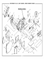
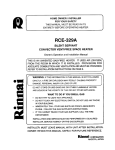
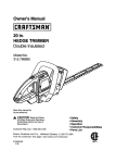
CRAFTSMAN
76 mm (3 in.) BELT SANDER
-- MODEL
NUMBER
SEE NOTE "A" PAGE 17
315.252220
12
6
7
11
8
14 15
18
2O
10
9
j
16
21
17
31
42
38'
16
•
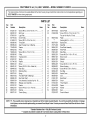
CRAFTSMAN
76 mm (3 in.) BELT SANDER
m MODEL
NUMBER
315.252220
The model
number
will beordering
found onrepair
a plate
attached to the motor housing. Always mention the model number in all correspondence
BELT
SANDER
or when
parts.
l
regarding your
1
PARTS LIST
Key
No.
1
2
3
4
5
6
7
8
9
10
11
12
13
14
15
16
17
18
19
20
21
22
23
24
25
26
27
Part
Number
970201-001
998367-001
979616-001
607776-002
614658-010
989368-000
996366-004
703493-809
996423-002
726693-004
989366-000
998372-001
616247-001
931744-059
999937-001
998401-001
999448-003
622167-012
998375-001
998373-002
999954-002
999945-004
999927-001
622347-001
999923-001
996370-001
998371-001
Description
Key
No.
Quan.
* Screw (#8-32 x 3/8 in. Pan Hd. T. F.) ...........
Belt Cover .....................................................
Logo Plate .....................................................
Driven Pulley .................................................
* Screw (#8-32 x 3/8 in. Pan. Hal.) ..................
Timing Belt ....................................................
Gear Housing Cover w/Bearing ....................
Washer .........................................................
Pinion ............................................................
* Screw (#8-32 x 7/8 in. Fil. Hal.) .....................
Pulley ............................................................
Tracking Screw .............................................
Spring ...........................................................
Washer .........................................................
Blower ...........................................................
* Screw (#10-32 x 3/8 in. Wafer Hal.) ..............
4
1
1
1
3
1
1
2
1
1
1
1
1
1
1
1
Wear Strip .....................................................
1
Retaining Ring ..............................................
2
Spring ...........................................................
1
Front Idler Roller w/Bearings ........................ 1
Idler Roller Shaft ...........................................
1
Yoke Assembly (Includes Key No. 19) ......... 1
Release Lever Assembly .............................. 1
Washer .........................................................
1
* Screw (#10-32 x 1/2 in. Pan Hd.) ................. 1
Bushing .........................................................
2
Torsion Spring ..............................................
1
Part
Number
28
29
967878-003
612665-006
30
31
32
33
34
35
36
37
38
39
40
41
42
43
44
45
46
47
48
49
50
51
52
998376-002
***
998378-001
703774-003
999942-001
998380-001
979614-001
989592-001
999931-001
999347-001
996393-001
989592-007
996398-001
617966-030
998394-001
999929-001
990495-001
613651-001
998895-001
616103-301
622448-000
622347-003
998368-001
972000-537
Description
Quan.
Glamor Plate .................................................
1
* Screw (#10-32 x 7/8 in. Pan Hd. T.F.)
For use with Key No. 50 only .......................
Platen ............................................................
2
1
Sanding Belt (3 in. x 21 in.) ............................. 1
Backing Pad ..................................................
1
Steel Ball .......................................................
1
Drive Roller Assembly ..................................
Wear Plate ....................................................
Data Plate .....................................................
1
1
1
* Screw (#8-10 x 1-1/8 in. Fil. Hd.) ..................
Blower Cover ................................................
Deflector .......................................................
Shroud ..........................................................
3
1
1
1
* Screw (#8-10 x 2-1/4 in. Fil. Hd.) ..................
Blower Housing .............................................
* Screw (#8-10 x 5/8 in. Pan Hd.) ...................
Dust Bag .......................................................
Handle Cover ................................................
Cord ..............................................................
Bend Relief ...................................................
Switch ...........................................................
Thrust Washer ..............................................
2
1
4
1
1
1
1
1
1
Spacer ..........................................................
Washer .........................................................
Gear ..............................................................
Owner's Manual
2
1
1
NOTE: "A" - The assembly shown represents an important part of the Double Insulated System. To avoid the possibility of alteration or damage
to the System, service should be performed by you r nearest Sears Repair Center. Contact your nearest Sears Retail Store for Service Center
information.
* Standard Hardware Item -- May Be Purchased Locally
*** Complete Assortment Available At Your Nearest Sears Catalog Order Or Retail Store
17
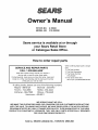
Owner's Manual
STOCK NO.
MODEL NO.
9 25222
315.252220
Sears service is available at or through
your Sears Retail Store
or Catalogue Sales Office.
How to order repair parts
When ordering repair parts always
give:
1. The Part Number
SERVICE AND REPAIR PARTS
CALL 1-800-665-4455 *
2. The Part Description
3. The Model Number:
315.252220
4. The name of the item:
Keep this number handy should you require a
service call or need to order repair parts.
tf ordering parts, make sure you have the name, make and
model no. of the merchandise and the name and number
76 mm (3 in.) Dustless Belt Sander
of the part you wish to order.
• If calling locally, please use
Regina - 566-5124
Toronto - 744-4900
Kitchener - 894-7590
Vancouver -
one of the following numbers:
Montreal - 333-5740
Halifax - 454-2444
Ottawa - 738-4440
420-8211
WE SERVICE
WE MAKE THIS PLEDGE
BECAUSE
WHAT
OUR CONCERN
WE SELL.
FOR OUR CUSTOMERS
DOES NOT END
WITH THE SALE. TO HONOR OUR PLEDGE, WE HAVE DEVELOPED
A TOP-NOTCH
SERVICE
PROGRAM STAFFED
BY HIGHLY TRAINED SPECIALISTS.
THEIR KNOWLEDGE
OF OUR NEW
PRODUCTS
IS CONSTANTLY
UPGRADED.
THEY USE ONLY PARTS SPECIFICALLY
DESIGNED
FOR YOUR FINE SEARS PRODUCTS.
Sold by: SEARS CANADA
INC., TORONTO
MSB 2B8