1
ND77
ND77
Modular POS Printer
User Guide
We would like to know
your opinion on this publication.
Please send us a copy of this page
if you have any constructive criticism on:
- the contents
- the layout
- the product.
We would like to thank you in advance
for your comments.
With kind regards,
Wincor Nixdorf International GmbH
RD PD1
Wernerwerkdamm 16
Gebäude Nr. 36
D-13629 Berlin
Fax: +49 30 3864 3075
Your opinion:
ND77, User Guide, Order No. 01750055814A
(ND77)
ND77
Modular POS Printer
User Guide
Edition July 2002
Copyright © Wincor Nixdorf International GmbH, 2002
The reproduction, transmission or use of this document or its contents is not permitted
without express authority.
Offenders will be liable for damages.
All rights, including rights created by patent grant or registration of a utility model or design,
are reserved.
Delivery subject to availability; technical modifications possible.
Contents
Manufacturer’s Certification .................................................................... 1
General Licence .......................................................................................... 1
FCC-Class A Declaration ............................................................................ 1
Tested Safety .............................................................................................. 2
Important Notes........................................................................................... 2
Introduction ............................................................................................... 4
About this manual........................................................................................ 4
Care of the ND77 ........................................................................................ 4
Recycling the ND77 POS Printer ................................................................ 6
Warranty ...................................................................................................... 7
Installation ................................................................................................. 9
Before Switching On ................................................................................... 9
Unpacking and Checking the Printer ........................................................ 9
Setting up the device ................................................................................ 9
Cabling of the ND77................................................................................ 10
DIP switches ........................................................................................... 10
Interfaces ................................................................................................ 10
Securing the data communication cable................................................. 11
Connecting to the mains power supply.................................................. 11
Disconnecting cables ............................................................................. 12
Connection to the POS system ................................................................. 12
Connecting peripherals ............................................................................. 13
Cash drawer........................................................................................... 13
Customer display .................................................................................... 13
The operator control panel ........................................................................ 14
Power ON/OFF ....................................................................................... 14
Receipt feed button................................................................................. 14
Journal feed button ................................................................................. 15
LEDs ....................................................................................................... 15
Operation of the ND77 POS printer ....................................................... 17
Document processing ............................................................................... 18
Changing the receipt and journal paper.................................................... 19
Changing the receipt roll .........................................................................19
Removing remaining receipt paper .........................................................20
Inserting the receipt roll ...........................................................................20
Changing the journal roll............................................................................23
Removing the journal paper ....................................................................23
Inserting the journal paper.......................................................................23
Changing the ribbon cassette....................................................................26
Notes on the automatic document detection...........................................28
DIP switches ..............................................................................................29
Self Test.....................................................................................................32
Replacing the print head............................................................................35
Adjusting the paper end detectors.............................................................37
Printing with the ND77 ...............................................................................39
Software Stamp Printing..........................................................................39
Logo printing............................................................................................40
Graphics printing .....................................................................................40
Appendix...................................................................................................41
Technical Data ..........................................................................................41
Dimensions with covers open .................................................................42
Paper Specification....................................................................................43
Receipt - and Journal paper (single ply) .................................................43
Document paper......................................................................................43
Print areas (Paper Roll Width 69.5 mm) .................................................44
Interfaces ...................................................................................................45
Cash drawer connector ...........................................................................45
Serial interface to the customer display .................................................46
Serial system interface ............................................................................46
Power supply cable .................................................................................48
Error messages via blink codes ...............................................................49
LED “ERROR” .........................................................................................49
Recoverable errors..................................................................................49
Unrecoverable errors...............................................................................50
All LED.....................................................................................................51
Control Sequences ....................................................................................53
Mounting the spacer in the paper compartment of ND77 .........................55
Print areas (Paper Roll Width 57.5 mm) .................................................57
Manufacturer’s Certification
General Licence
The device complies with the requirements of the EEC directives
89/336/EEC with regard to “Electromagnetic compatibility” and
73/23/EEC “Low Voltage Directive”(in case the device has its own
power connection). Therefore, you will find the CE mark on the
device or packaging.
FCC-Class A Declaration
This equipment has been tested and found to comply with the limits for a
Class A digital device, pursuant to part 15 of the FCC Rules. These limits
are designed to provide reasonable protection against harmful interference when the equipment is operated in a commercial environment. This
equipment generates, uses, and can radiate radio frequency energy and,
if not installed and used in accordance with the instruction manual, may
cause harmful interference to radio communications.
Operation of this equipment in a residential area is likely to cause harmful
interference in which case the user will be required to correct the interference at his own expense.
Le présent appareil numérique ne génère pas de bruits radioélectriques
dépassant les limites applicable aux appareils numériques de la “Class A”
prescrites dans le Règlement sur le brouillage radioélectrique édicté par le
ministère des Communications du Canada.
GB - 1
Manufacturer’s Certification
Important Notes
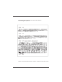
Tested Safety
The ND77 has been provided with the symbol for
UL and cUL.
Manufacturer’s Certification
Important Notes
Important Notes
The accessory printer ND77 is for use with UL listed POS systems
and/or UL listed computers. The printer complies with the relevant safety
regulations for information technology equipment. Should you have any
doubts about the permissibility of installation in a certain environment
(e.g. electricity systems, no use of PEN conductors! ), please contact the
Wincor Nixdorf Customer Service.
o
o
o
o
o
GB - 2
lf the printer is brought into the room of operation from a cold environment, dewfall (condensation) can occur. Before turning on the printer,
it must be completely dry; it is therefore necessary to observe an acclimatization period of at least two hours.
When setting up the printer, ensure that there is easy access to the
power socket on the printer and/or to the grounded-contact mains
socket.
Position the leads and cables so that no one steps on or trips over
them.
To disconnect the printer from the supply voltage, switch off the printer and disconnect the power supply plug.
Make sure that no objects (for example, paper clips) or liquids get
inside the printer. Electric shocks or short circuits can be caused in
this way.
Manufacturer’s Certification
Important Notes
o
Never plug or unplug data communication lines during thunderstorms.
o
Protect the ND77 from vibrations, dust, moisture and heat.
o
o
o
The printer should only be transported in its original packing and
protective material. This protects the printer against damage from
knocks and bumps.
Turn off and unplug the printer immediately if an emergency occurs
(for example, if the printer housing is damaged or any foreign substance gets into the printer). Call your Wincor Nixdorf Customer Service.
Always dispose of used parts, such as printer ribbons, in an environmentally safe manner (see chapter “Recycling”).
The printer may be repaired by authorized qualified personnel only.
Repairs made by an unauthorized service provider could not only
jeopardize the safety of the user, but also lead to cancellation of all
warranty and liability agreements.
GB - 3
Introduction
The modular ND77 Pin Printer is a high-performance and economical
POS system printer of receipts, journals and documents, which is easy
to install (plug-in-system), easy to use, and which requires a minimum of
space. The ND77 has no trouble even with documents; it can print documents of up to A5 in size - quickly and easily. Larger documents can be
inserted.
The printer is equipped with connections for a customer display and a
cash drawer, which means that the number of interfaces on the system
unit of your POS can be reduced. Because the industrial standards have
been employed - system interface V.24 - the investment you have made
for your POS system is protected.
With its performance, the ND77 is an essential supplement to your entire
point of sale system!
About this manual
This manual provides you with all the information you require to ensure
that your ND77 Printer operates without a single hitch. lt tells you everything you need to do before switching on the printer, how to connect additional devices, and which adjustments might be necessary from time to
time to ensure that your ND77 operates reliably. We therefore ask you to
read the appropriate sections of this manual before using your printer.
If you have an ND77 without journal station or without bon station please
skip the according hints.
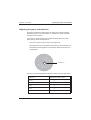
Care of the ND77
Clean your printer at regular intervals with a commercially available
cleaner for sensitive surfaces. Never use acidic solvents.
GB - 4
Introduction
Introduction
Care of the ND77
Care of the ND77
Before cleaning make sure that the power is switched off, the power supply
plug is disconnected and that no moisture gets into the printer.
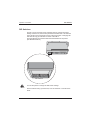
To clean the inner housing use a soft brush or a small vacuum cleaner.
Please make sure that there is no remaining paper in the carrier area.
Carefully clean the cutter area to remove paper dust. Make sure the ribbon is free of paper dust. Always keep the area of carrier-home sensors
clean (see picture below).
Carrier-home
sensor
Clean the deflection prism located on the document plate (see figure below) with a soft cloth.
deflection prism
GB - 5
Introduction
Recycling
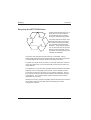
Recycling the ND77 POS Printer
Environmental protection does not
begin when it is time to dispose
of the technical device; it begins
during the manufacturing process.
Your ND77 Printer has been manufactured without the use of CFCs
and CCHS, and produced mainly
from reusable components and
materials. The processed plastics
can, for the most part, be recycled.
Even the precious metals can be
recovered, thus saving energy and
valuable raw materials.
Recycling
At present, there are still some parts that are not reusable. Wincor
Nixdorf (WN) guarantees the environmentally safe disposal of these parts
in a Recycling Center, which is certified according to ISO 9001.
So please do not just throw your ND77 on the scrap heap when it has served its time. Make use of our environmentally sound and up-to-date recycling methods!
The operation of your printer also generates waste material that should be
disposed of in an ecologically sound manner. Wincor Nixdorf provides
a recycling box that you can place on your company premises. The low
price you pay for the box also includes collection and complete recycling
of the ribbons. For more information, please contact the branch office
responsible for your area.
Should you have any questions regarding Wincor Nixdorf and environmental protection please contact WN under the following fax number:
+49 (0) 5251 8-26709
GB - 6
Introduction
Warranty
Warranty
Wincor Nixdorf guarantees a limited warranty engagement for 12 months
beginning with the date of delivery. This warranty engagement
covers all those damages which occur despite a normal use of the product.
Damages because of
- improper or insufficient maintenance,
- improper use of the product or unauthorized modifications of the
product,
- inadequate location or surroundings
will not be covered by the warranty.
All parts of the product which are subject to wear and tear such as the
printhead or the ribbon cassettes are not included in the warranty
engagement.
Please order spare parts at the Wincor Nixdorf customer service.
Warranty
In case your ND77 works faulty and you are going to send it to the
Wincor Nixdorf Customer Service, make sure to remove the printhead before. Our Service then will replace your printer with a faultless ND77 in
which you only have to insert your printhead again. How to easily do this is
described on the pages 35 and 36 in this manual.
Thus you ensure a quick and low-cost repair of the printer.
GB - 7
Warranty
GB - 8
Introduction
Installation
Before Switching On
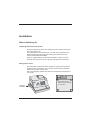
Unpacking and Checking the Printer
Unpack the printer and see if the contents of the box matches the particulars on the packing list.
If any damage has occurred in transit, or if there is any discrepancy between the package contents and the packing list, please inform your
Wincor Nixdorf outlet immediately.
Keep the original packing and protective material in case you need to
transport the printer in the future to protect against knocks and bumps.
Setting up the device
Set up the ND77 where it will not be exposed to extreme environmental
conditions such as vibrations, dust, moisture, heat and strong magnetic
fields. Put the printer on level area.
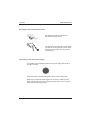
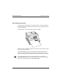
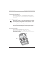
Pull out the shipping restraint and click it into the slots at the underside of
your printer.
Shipping
Restraint
Deposit the shipping
restraint at the underside
of the printer
GB - 9
Installation
Before Switching On
Cabling of the ND77
Installation
Before Switching On
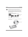
The printer should be installed in the following order:
Plug in and secure the data communication cable.
Plug in the power supply cable into the HOSIDEN power cord
receptacle on the printer
Plug in the other end of the cable into the power cord receptacle of the BEETLE system
or
plug in the power cable of an external power supply unit into the
grounded-contact mains supply socket.
DIP switches
You can change the settings of your printer by using the DIP switches. For
detailed information see the section on “DIP switches”.
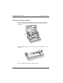
Interfaces
RJ12-Plug cash drawer
Interface customer display
V24-System interface
24V Voltage in (HOSIDEN connector)
GB - 10
Installation
Before Switching On
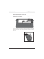
Securing the data communication cable
The interface connectors are secured
manually turning the screws.
The interface connectors with screws made
of metal can be secured with a screw driver.
Screws made of plastic must be secured
manually only.
Connecting to the mains power supply
You will find a 3pin HOSIDEN socket for the power supply at the back of
the ND77 housing .
Connect the ND77 with the POS system via the power supply cable.
When using an external power supply unit connect the cable for power
supply with the ND77 and plug in the power cable of the unit into a grounded-contact mains supply socket.
GB - 11
Installation
Connection to the POS system
Disconnecting cables
Never unplug a cable by pulling at the cable itself; always take hold of the
actual plug body. Follow the procedure described below when disconnecting cables:
Switch off all power and device switches.
Unplug all data communication cables from the data networks.
Unplug all power plugs from the grounded-contact mains power
sockets.
Unplug all cables from the devices.
Connection to the POS system
Connection to the POS system
The accessory printer ND77 is for use with UL listed POS systems and/or
UL listed computers!
The ND77 can be connected to the V.24 interface (serial interface) of the
POS system.
GB - 12
Installation
Connecting peripherals
Connecting peripherals
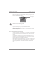
Cash drawer
Connecting peripherals
The ND77 has a RJ12 jack for connecting a cash drawer. To prevent malfunctions, make sure that the connector is plugged firmly into the socket.
Power is supplied to the cash drawer via this socket.
When connecting cash drawers, the construction level 1 (Release 4) for
the KA16 or KA17 is absolutely necessary! The construction level is noted
on a label on the bottom of the cash drawer.
Customer display
The customer display is connected to the serial interface. The interface
connection on the ND77 is a 9pin D-sub connector.
To prevent possible malfunctions, make sure that the connector for the
customer display is plugged firmly into the socket. The power is supplied
via this jack.
GB - 13
Installation
The operator control panel
The operator control panel
The operator control panel
The components which make up the operator control panel include the power switch, LEDs and paper feed buttons. The operator control panel is located at the top of the printer. Access to the power switch is covered by
the top cover of the printer.
ON
OFF
POWER
ERROR
DOCUM.
R
J
PAPER END
RECEIPT
JOURNAL
Power ON/OFF
This button switches the power on or off. The button can be accessed only
when the top cover of the printer is open. This prevents the printer being
turned off by accident.
Receipt feed button
Press the receipt feed button once to advance receipt paper one line. The
line spacing corresponds to the default value of 1.6". You can also hold
down the button to feed receipt paper continuously.
GB - 14
Installation
The operator control panel
With the cover open, this button is always enabled even if it is locked by
the command ESC c5.
Journal feed button
Press the journal feed button once to advance journal paper one line. The
line spacing corresponds to the default value of 1,6". You can also hold
down the button to feed journal paper continuously.
With the cover open, this button is always enabled even if it is locked by
the command ESC c5.
LEDs
Green LED “POWER”
The power light is on when the printer power
is on.
Red LED “ERROR”
This LED is on when the printer cover is open.
The LED is blinking if an error occurs (see page 49).
In normal state the LED is off.
Yellow LED “DOCUMENT”
This LED blinks while the printer is waiting for
document paper. It lights permanently when a
document is inside the printer and blinks twice
when the document paper is being ejected.
The LED is off when the document station is
not selected.
Red LEDs “PAPER END”
The LEDs are on if either the receipt station “R”
or the journal station “J” recognized a paper
end or if paper rolls are not installed.
The LEDs are off if paper is available on the
respective print stations.
GB - 15
The operator control panel
GB - 16
Installation
Operation of the ND77 POS printer
The ND77 POS printer has 9dot matrix printing mechanism serving
the three printing stations for receipt, journal and documents. Character
resolution is 9 x 9 dot matrix or 7 x 9 dot matrix, depending on the
character types you select from your application software.
The ND77 provides you with the possibility of controlling the line feed of
the receipt and journal paper via two buttons on the operator control panel.
For reasons of safety, the printing and cutting devices are shut down as
soon as the printer cover is opened.
The ND77 is supplied with a Flash EPROM to load in firmware updates
without opening the printer.
An individual company logo can be created by means of a block print
which is produced in graphic print quality. The logo is loaded into the
printer memory through your application software. Your ND77 can print
logos that were created up to a size of 25 856 dots.
An individual stamp (software) can be stored in the Flash EPROM of the
ND77 permanently. It still remains after switching off the printer.
Additional printer features are efficient printing and simple operation.
All consumables for the printer, such as receipt and journal paper or
ribbon cassettes can be ordered from WN branch office.
For the sake of the environment, always dispose of used materials
properly (see chapter on recycling).
GB - 17
Document processing
Operation of the ND77
Operation of the ND77
Document processing
Document processing
The ND77 prints documents up to a size of DIN A5. Consult the appendix
for the print area and the paper specifications. Documents larger than DIN
A5 can be inserted.
When printing a check, bold printing should be enabled.
When the yellow LED flashes, place the document to the right of the guide
edge of the document plate.
This applies particularly to documents which are smaller than DIN A5 so
that the documents sensors can recognize the paper and draw it in correctly. Push the document towards the document infeed as far as possible.
Always insert the paper in such a way that the side to be printed on is
facing downwards. The side of the document that you place to the guide
edge of the document plate must not be perforated!
GB - 18
Operation of the ND77
Changing the receipt and journal paper
After processing, the document will be ejected. The yellow LED flashes
twice. Now you can remove the document.
If the document sensors recognize a document end during document
processing, although print data still located in the print controller, this will
lead to a print stop (only if print stop is enabled). The document will be
ejected. When the print stop is enabled the printer will stop printing when
the document sensors recognize the end of a document. This occurs even
though print data remains in the print controller. To continue, or complete
printing, take out the document and insert a second document when the
yellow LED flashes.
Changing the receipt and journal paper
Changing the receipt and journal paper
This section provides a detailed description of how to change the receipt
and journal paper rolls.
Changing the receipt roll
When a red stripe appears on the printed receipt, or the “paper end” LED
lights up on the control panel, a new receipt roll should be inserted. Change the receipt roll as follows:
GB - 19
Operation of the ND77
Changing the receipt and journal paper
Removing remaining receipt paper
Press the release button (see arrow) and lift up the housing cover to gain
access to the paper roll. You can remove the remaining paper by pressing
the line feed button on the control panel.
Never forcefully pull out the paper caught in the print mechanism. Doing
so will damage the transport rolls.
Take out the empty paper roll. If the end of the receipt roll is glued to the
paper roll, cut the paper from the roll.
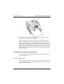
Inserting the receipt roll
Press the release button and lift up the housing cover.
Make sure that the paper
on the new paper roll is
cut or torn evenly.
GB - 20
Operation of the ND77
Changing the receipt and journal paper
Insert the new paper roll into the paper compartment as shown in the
illustration below.
Press the button to the left of the receipt compartment (see arrow) and lift
up the printing mechanism.
GB - 21
Changing the receipt and journal paper
Operation of the ND77
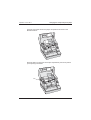
Next, guide the end of the paper from below into the receipt output. Push it
until it is visible on top.
2
Check whether the paper is straight and close the printing mechanism by
pressing on the spot marked with arrow 2 until the printing mechanism
snaps into place.
Tear off the excess receipt
paper by pulling downward
at the tear-of edge of the
receipt output.
Finally close the housing cover.
GB - 22
Operation of the ND77
Changing the receipt and journal paper
Changing the journal roll
When you see a red stripe on the journal paper or when the paper end
LED “J” lights up, it is time to insert a new journal roll. Change the journal
roll as follows:
Removing the journal paper
When the paper end LED “J” on the control panel lights up, there are only
a few centimetres of journal paper left in the paper compartment. Lift up
the housing cover by pressing the release button.
Never forcefully pull out the journal paper when the print mechanism is
closed. Doing so will damage the transport rolls.
Tear through the journal paper and remove the journal paper from the
take-up spool. Remove the empty paper roll from the journal compartment.
Inserting the journal paper
Press the release button and lift up the housing cover.
Make sure that the paper on the new paper roll is evenly cut.
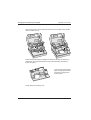
Press the button to the left of the receipt compartment (see arrow) and lift
up the printing mechanism.
GB - 23
Changing the receipt and journal paper
Operation of the ND77
Insert the new paper roll into the paper compartment as shown
in the illustration below.
Next, push the end of the paper from below into the journal guide. Push it
until it is visible on top.
GB - 24
Operation of the ND77
Changing the receipt and journal paper
Pull out enough paper from the journal opening (approx. 30 cm) to allow it
to be threaded into the take-up spool.
Check whether the paper is straight and close the printing mechanism.
Fold the paper over approx. 1cm
and push it into the slot of the takeup spool.
Turn the spool several times to
ensure a secure seating.
Lay the paper upon the guiding roll and place the spool into its reception
slot.
Now, close the housing cover.
GB - 25
Operation of the ND77
Changing the ribbon cassette
Changing the ribbon cassette
Changing the ribbon cassette
Press the release button and lift up the housing cover. Press the button
to the left of the receipt compartment (see arrow) and lift up the printing
mechanism.
Lift the document plate forward. You see the ribbon cassette and you can
remove it.
Be sure to dispose of the ribbon cassette properly.
GB - 26
Operation of the ND77
Changing the ribbon cassette
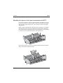
Take the new ribbon cassette out of the pack.
Before inserting the cassette into the printer housing, tighten the ribbon by
turning the knob on the cassette.
Insert the cassette in a way that the guiding pins beside the cassette will
slide into the recesses of the printer housing (see example in the magnified view).
GB - 27
Changing the ribbon cassette
Operation of the ND77
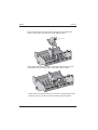
Make sure that the ribbon will be threaded under the guiding pins of the
print head (see illustration below).
Guiding Pin
Caution! The print head may be hot!
Tighten the ribbon again by turning the knob several times.
First close the document plate and then the printing mechanism. Finally
close the housing cover.
Notes on the automatic document detection
In order to guarantee a good readability for the automatic document detection the indicated lifetime of the colour ribbons is at a limit of 23% for the
contrast.
You will find the exact limit for the automatic document detection in the
description of your scanner. Depending on the type of device a considerable lower lifetime of the colour ribbon might occur.
With regard to the document detection you may increase the lifetime of the
colour ribbon by printing the text on a bright background, by selecting the
double print option and by using violet colour ribbons instead of black
ones.
GB - 28
Operation of the ND77
DIP Switches
DIP Switches
DIP Switches
Operation of the ND77
The ND 77 has two banks of DIP switches that can change the printer
settings. Please note, that the line parameters between the V.24 interface
of the printer must correspond to those of the host system. Changing DIP
switches will only get valid after a restart of the ND 77.
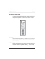
The DIP switches are located underneath the backside of the printer
(see illustration below).
1
2 3
4 5
DSW 1
6 7 8
1
2 3
4 5
6 7 8 9 10
DSW 2
DIP switches
Turn off the printer to change the DIP switch settings.
Set the switches using a pointed tool, such as tweezers or a small screw
driver.
GB - 29
Operation of the ND77
DIP Switches
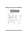
The DIP switches are allocated as follows:
OFF
1
ON
2 3
4 5
6 7 8
1
2 3
4 5
6 7 8 9 10
DSW 2
DSW 1
Bank 1
Bank 2
Each switch functions as follows:
Bank 1
DIP
1
2
3
4
5
6
7
8
Function
ON
OFF
Cutter
Deactivated
Activated
Parity
Enabled
Disabled
Parity selection Even
Odd
Transmission speed (see the table below)
Transmission speed (see the table below)
Connection of
display module* Connected
Not connected
Data receive
error
Ignored
Prints ?
Handshaking
XON/XOFF
DTR/DSR
Default
OFF
OFF
OFF
OFF
OFF
OFF
OFF
OFF
* Effective when a direct connection display module is connected to the
printer`s display module connector.
Transmission speed (BPS)
9600
2400
4800
19200
GB - 30
DIP4
OFF
OFF
ON
ON
DIP5
OFF
ON
OFF
ON
Operation of the ND77
DIP Switches
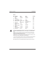
Bank 2
DIP Function
1
Auto line
feed
2
Reserve
3
Font selection
4
Carriage speed
5
Busy condition
6
7
8
9
10
Document
Ejection
I/F Pin6 ResetSignal
I/F Pin25 ResetSignal
Document
inverse printing
Roll width
ON
Always
enabled
OFF
Always
disabled
Default
9x9
LOW
Receive buffer
full
eject and not
retain
7x9
HIGH
Off-line or
receive buffer full
eject and
retain
Enabled
Disabled
OFF
Enabled
Disabled
OFF
Enabled
57,5 *
Disabled
69,5
OFF
OFF
OFF
OFF
OFF
OFF
OFF
OFF
When pin 6 of the interface connector is used for the reset signal, the printer is reset at MARK (signal level -5 to -15 V, logic “1") on the RS-232C
level.
When pin 25 of the interface connector is used for the reset signal, the
printer is reset at SPACE (signal level +5 to +15 V, logic ”0") on the RS232C level or at HIGH on the TTL level.
If DIP switch 7 or 8 of the bank 2 is ON while the printer is turned on, the
printer may be reset, depending on the signal state.
* If you have mounted a spacer in order to use paper rolls with smaller roll
width (see appendix) please set the DIP switch 10 at bank 2 to ON.
DIP switches must not be operated while the printer power is turned on.
GB - 31
Operation of the ND77
Self Test
Self Test
Self Test
To start a printer self test proceed as follows:
o
Press the release button and lift up the housing cover.
o
Turn on the power with the power switch on the operator control panel.
o
Close the housing cover quickly and press either the receipt or journal
line feed button until the printout starts.
Depending on the pressed button the printout is done at the journal station
or the receipt station
Operation of the ND77
GB - 32
You will find a sample printout on the next page.
GB - 33
Insert a document as soon as the yellow LED is blinking.
The following will be printed:
Fifteen seconds after the self test, the ND77 will reset and is ready to print.
GB - 34
Operation of the ND77
Replacing the print head
Replacing the print head
Replacing the print head
The print head can be replaced as follows:
Press the release button and lift up the housing cover. Turn off the power
with the power switch at the operator control panel.
Press the button to the left of the receipt compartment (see the arrow) in
order to raise the printing mechanism.
Operation of the ND77
Lift the document plate forward and remove the ribbon casette.
GB - 35
Replacing the print head
Operation of the ND77
Caution! The print head may be hot! Allow the print head to cool before
touching it.
Position the print head to the left hand side.
To remove the print head from its bracket, open the holding clips.
Press the clips to the left and to the right. The print head is now loose and
can be removed easily.
Then unplug the flexible cable from the print head socket.
To insert the new print head, follow the same procedure in reverse order.
Should you send a faulty ND77 to the Wincor Nixdorf Customer Service,
remove the printhead before. See also page 7 in this manual.
GB - 36
Operation of the ND77
Adjusting the paper end detectors
Adjusting the paper end detectors
Adjusting the paper end detectors
Operation of the ND77
The paper end detectors detect when the paper end is almost reached.
Software programs can use the ESC c 4 command to enable or disable
the paper end recognition.
If you want to change the amount of paper remaining when the printer
stops printing, follow the steps below:
o
o
Open the housing cover and remove the paper roll.
Determine the point on the paper roll at which you want the paper roll
end detection to be triggered. Then measure distance A as shown in
the illustration.
Distance A
Find the corresponding adjustment position number from the table below.
Distance A
Adjustment position number
10 mm
5
8 mm
4
6 mm
3
4 mm
2
2 mm
1
GB - 37
Operation of the ND77
Adjusting the paper end detectors
Locate the adjusting screws shown in the illustration below.
5
4
3
2
2
1
3
1
To change the adjustment position please proceed as follows:
Loosen the appropriate adjusting screw with a coin or a screwdriver (1).
Move the screw to the desired position (2).
Tighten the adjusting screw (3).
There may be some difference between the measured distance A and the
actual sensing position.
GB - 38
Operation of the ND77
Printing with the ND77
Printing with the ND77
Printing with the ND77
The ND77 offers you three different possibilities to print on receipts, journals and documents:
the software stamp printing
the logo printing
graphics printing
You can use the logo or graphics printing on all three stations (receipt,
journal, document), whereas software stamp printing is designed for the
receipt station only.
Software Stamp Printing
If you want to print text or graphics frequently or permanentely on a receipt
e.g. your company name or trade-mark as header, we recommend to use
software stamp printing.
Example: You design your trade-mark by means of a standard graphics
software program. In doing so please make sure to create those (bitmap)
files as black and white files and to save them later accordingly.
The maximum size of a stamp you can print with your ND77 is an area of
25 856 dots. The maximum width (W) is 180 pixel (= 61.2 mm) with a paper roll width of 69.5 mm. The height (H) of the stamp is variable, however, please mind that W x H ≤ 25 856. If you use paper rolls with a width
of 57.5 mm the maximum stamp width is 144 pixel (= 49 mm).
Having created your bitmap stamp file (black and white!) you then should
preferably save it as a black and white file in the same directory in which
you already stored the special load software (Flash-ROM Loader Utility)
for the stamp file.
With this loader utility you can load your file into the Flash EPROM of the
ND77. Thus your software stamp remains permanently stored and will not
get lost after the printer has been switched off.
GB - 39
Printing with the ND77
Operation of the ND77
The stamp will be printed on the receipt by sending the control sequence
ESC o.
You will find details on the “Flash-ROM Loader Utility” and on printing a
software stamp in the “ND77 Programmers Guide” (see also page 54 in
this User Manual).
Logo printing
The logo print is recommendable for graphics or texts which are often
modified and which need not be stored in the printer for a longer period
of time.
Example: You define a logo which is supposed to appear on the receipt,
journal or a document. When designing the logo you will have to adhere
to the same parameters as described before when creating a software
stamp. Subsequently, the maximum size of your logo is an area of 25 856
dots.
The print data will be loaded into the RAM of your ND77 by sending the
control sequence GS *. By sending the GS / sequence these data can
finally be printed.
For further information on the logo printing, please read also the
“ND77 Programmers Guide”.
Graphics printing
In case that stamp and logo printing should not be sufficient, the singleline graphics printing offers another possibility to print frequently modifying
data on the paper. In this case the graphics data will be transferred line by
line and will not be stored in the printer. The graphics printing is activated
by sending the control sequence ESC *.
For further information on graphics printing also refer to the
“ND77 Programmers Manual”
GB - 40
Appendix
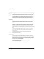
Technical Data
Footprint:
Height
Width
Depth
215 mm
251 mm
280 mm
Weight (w/o paper)
approx. 6kg
Climatic Category
Operating Temperature
IEC 721Class 3K3
+5 until +40°C
Power supply
External power supply unit
24V / 2.0 A or via BEETLE /L
Power
approx. 50 watts
Print method
9-pin, serial impact
dot matrix 9x9 / 7x9
Print columns
Receipt/Journal max. 40
Document max. 88
Print speed:
typ. receipt (10 char)
full print line (40 char)
14 lines/sec
6 lines/sec
Logo print
(max. size 25 856 dots)
via graphic printing quality
Ribbon
violet or black
System interface
1x RS232c
Interfaces
1x cash drawers (RJ12)
1x WN customer display
GB - 41
Appendix
Technical Data
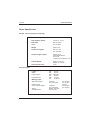
Dimensions with covers open
Appendix
Technical Data
71,5
385
The following values also refer to a build in printer (all dimensions in mm).
38
280
Increase this value up to 125 when you use DIN A4 documents.
GB - 42
58
83
Appendix
Paper Specification
Paper Specification
Receipt - and Journal paper (single ply)
Paper Specification
Roll diameter (outside)
max. 83 mm
Roll diameter (inside)
12 mm +0, -2 mm
Roll width
Option
69,5 ±0,5 mm
57,5 ±0,5mm
Weight
60g/m² ±4%
Thickness of paper
max. 0,1 mm
min. 0,06 mm
Useable length of paper
approx. 60 m.
- Red stripes before
end of roll.
- Paper end not glued to core
Smooth (Bekk)
inside 14 - 56 sec.
outside 14 - 40 sec.
z 100
Fibre-material class
Document paper
Single ply paper
Length
Width
Paper weight
Paper thicknes
Multi ply paper
With carbon paper
Carbon paper
Chem. Contact paper
Gluing
Total thickness
min.
70 mm
min.
70 mm
max. 300 g/m²
min.
60 g/m²
max.
0,5 mm
min.
0,08 mm
1st sheet
2nd - 4th sheet
1st sheet
2nd - 4th sheet
header, right, left
max. 0,5 mm
50 - 80 g/m²
35 - 55 g/m²
24 g/m²
50 - 80 g/m²
40 - 60 g/m²
GB - 43
Appendix
Paper Specification
Print areas (Paper Roll Width 69.5 mm)
The following illustrations show the print area of the three print stations
with a paper roll width of 69,5 mm and a document of DIN A5 format.
The values are indicated in mm in relation to the home position of
the print head (see also page 53).
7,3
69,5
69,5
61,2
4,3 +/-2
61,2
4 +/-2
3 +/-2
RECEIPT
5,5 +/-2
JOURNAL
136
4,2 +/- 0,5
Head line
8,3
DOCUMENT
DOCUMENT
10
Foot line
136
GB - 44
4,2 +/- 0,5
Appendix
Interfaces
Interfaces
Interfaces
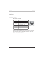
Cash drawer connector
RJ12 connector pin usage
PIN
Description
1
Frame Ground
2
Opening pulse for cash drawer 1
3
Status cash drawer 1 and 2
4
+24V DC
5
Opening pulse for cash drawer 2
6
Signal Ground
1
6
The Wincor Nixdorf cash drawers KA16, KA17 and KA18 can be connected by cash drawer cables ; cable lengths: 0.8m (CR KB - 0940); 1.5m
(CR KB - 0930); 5.0m (CR KB - 0941).
GB - 45
Appendix
Interfaces
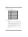
Serial interface to the customer display
Pin assignment of the 9pin D-Sub connector
PIN
Assignment
1
P12V
2
RXD
3
TXD
4
NC
5
GND
6
NC
7
RTS
8
CTS
9
NC
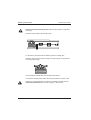
Serial system interface
A standard cable for connecting printers to the serial interface is used
to connect the ND77 to a PC or a PC-compatible unit (e.g. BEETLE
Systems).
This cable has a 25-pin D-sub connector on the end connecting to the printer. At the end connecting to the system it has a 9-pin D-sub connector
male or female depending on the systems interface.
If you are connecting to a BEETLE system with voltage-supplied COM
interface, your local branch office can supply you with the appropriate
cable. Gender-changers must not be used.
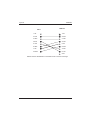
The following illustration shows the connector pin allocation and connection of the cable.
GB - 46
Appendix
Interfaces
ND77
BEETLE
1 NC
1 NC
2 TXD
2 RXD
3 RXD
3 TXD
4 RTS
4 DTR
5 CTS
5 SG
6 DSR
6 DSR
7 SG
7 RTS
20 DTR
8 CTS
9 NC
Cables must be shielded and connected to both connector housings.
GB - 47
Appendix
Interfaces
Power supply cable
The illustration below shows the Pin assignment of the power supply cable
between the ND77 and the BEETLE system.
ND77
24V Input
1 +24V
1 +24V
2 Ground
2 Ground
3 Power ID
3 Power ID
Shell is
earth
GB - 48
BEETLE
24V Output
Shell is
earth
Appendix
Blink codes
Error messages via blink codes
LED “ERROR”
Appendix
Blink codes
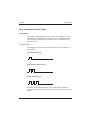
As described in the chapter “Operator Control Panel”, blinking of the red
LED “ERROR” indicates that an error has occured. The respective blink
codes are shown graphically in the following section. The blinking cycle
lasts about 2 sec.
Recoverable errors
The following errors can be recovered by DLE ENQ 1 or DLE ENQ 2 control command.
Automatic cutting error
Home position detection error
Carrier detection error
Should the errors mentioned above occur, check whether the ribbon is
blocking or whether there is residual paper in the printer housing - if so, remove it.
GB - 49
Appendix
Blink codes
Document ejection error
Remove possible paper jam and clean the deflection prism (see chapter
“Care of the ND77")
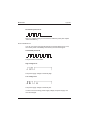
Unrecoverable errors
You can not recover from the following errors. Should these errors occur,
turn off the power immediately and contact your technical support.
Overheated print head
The print head is overheated.
High voltage error
The power supply voltage is extremely high.
Low voltage error
The power supply voltage is extremely low.
In case of errors involving power supply voltage, the power supply unit
must be changed.
GB - 50
Appendix
Blink codes
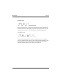
Thermistor error
The termistor is malfunctioning or not installed. The foil cable of the print
head is malfunctioning or not connected.
All LED
The following unrecoverable errors may occur when switching on the printer, all LEDs will be blinking in a cycle of approx. 4 sec:
Hardware error
This error refers to RAM, ROM, microcontroller. The blink code will be repeated continuously. The controller has to be changed.
Loading error
With a loading error (wrong checksum), the blink code will be repeated
continuously. The Flash EPROM has to be changed.
GB - 51
Appendix
Blink codes
Firmware error
When a firmware error occurs (wrong checksum) the blink code will be repeated three times. Subsequently, the printer is in loading mode. The yellow LED “Document” is on. It is necessary to load the firmware again.
Checksum error
The blink code will appear once when a checksum error occurs after power up. A checksum error may occur at the self test, the character set, the
software stamp or at the space page. You may find further information
about the checksum error on the printout of the self-test.
GB - 52
Appendix
Control Sequences
Control Sequences
Control Sequences
The control sequences of the printer controller are based on the ESC/POS
standard. The following list shows all the available sequences of the ND77.
Code
Function
LF
FF
CR
DLE EOT
DLE ENQ
RS
ESC SP
ESC !
ESC $
ESC %
ESC &
ESC *
ESC ESC 2
ESC 3
ESC <
ESC =
ESC ?
ESC @
ESC C
ESC E
ESC G
ESC J
ESC K
ESC R
ESC U
ESC \
ESC a
ESC c 0
ESC c 1
ESC c 4
ESC c 5
ESC d
Print and line feed
Print and eject document paper
Carriage Return
Transmit real time status
Real time request to printer
Journal Tab
Set right side character spacing
Select print modes (all stations)
Set absolute print position
Select / cancel user-defined character set
Define user-defined characters
Select bit image mode
Turn on / off underline mode
Set 1/6" line spacing
Set line spacing
Return home
Select peripheral device
Cancel user defined characters
Initialize printer
Select document eject length
Turn on / off emphasized mode
Turn on / off double strike mode
Print and line feed
Print and reverse line feed
Select an international character set
Turn on/off unidirectional printing mode
Set relative print position
Select justification
Select print paper(s)
Select paper(s) for setting line spacing
Select paper sensor to stop printing
Enable / disable all panel buttons
Print and execute n line feeds
GB - 53
Appendix
Control Sequences
Code
Function
ESC e
ESC f
ESC i
ESC m
ESC o
ESC p
ESC t
ESC u
ESC v
ESC z
Print and reverse feed n lines
Set document paper waiting time
Execute full cut
Execute partial cut
Print software stamp
Generate pulse (for cash drawer)
Select character code table
Transmit peripheral device status
Transmit paper detector status
Turn on / off parallel printing mode
for receipt and journal
Turn on / off upside-down printing mode
Transmit real time printer status
Define downloaded bit image
Print downloaded bit image
Select print speed and head energizing time
Transmit printer ID
Set vertical motion unit
Enable / disable automatic status back
Transmit status
ESC {
GS ENQ
GS *
GS /
GS E
GS I
GS P
GS a
GS r
For programming your printer, please find a detailed description of the
control sequences, the document handling and character pages in the
“ND77 Programmers Guide”.
GB - 54
Appendix
Spacer
Mounting the spacer in the paper compartment of ND77
Spacer
If you want your ND77 to print on paper rolls with a roll width of 57,5 mm
(± 0,5 mm) you have to insert a spacer. Therefore, first press the release
button and lift up the housing cover. You now have access to the paper
compartment.
Please note that the deflection roller (see arrow) is tapering in your ND77
from right to left. Only then it is possible to insert the spacer. Otherwise
the complete paper compartment has to be exchanged ! In this case please contact your local WN branch office or technical service.
First bend the spacer as shown in the picture below and guide the lower
catch underneath the deflection roller.
GB - 55
Appendix
Spacer
Now insert the spacer into the guidance (see picture) by pressing the
spacer´s upper catch from above on to the deflection roller.
Spring catches
Finally press the two spring catches of the upper catch (see above) into
the marked holes (see arrow) until you hear them click into place.
Please mind to set the DIP switch 10 on bank 2 to ON (see chapter “DIP
switches”, page 27), the firmware then will adjust the print position.
GB - 56
Appendix
Paper Specification
Print areas (Paper Roll Width 57.5 mm)
The following illustration shows the print area of the print stations bon and
journal with a paper roll width of 57.5 mm.
Paper Specification
The values are indicated in mm in relation to the home position of the
print head.
31.3
57.5
57.5
49
4,3 +/-2
49
4.2 +/-2
RECEIPT
3.5 +/-2
5 +/-2
JOURNAL
GB - 57