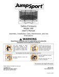
1
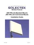
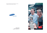
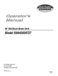
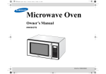
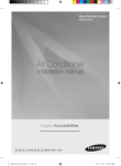
Wired Remote Control Basic :MWR-WE00 Model :MWR-WE10 Model Code : MWR-WE10 WIRED REMOTE CONTROL CONTENTS 1. Precautions 2. Product Specifications 3. Disassembly and Reassembly 4. Troubleshooting 5. Exploded Views and Parts List 6. PCB Diagram MWR-WE10 7. Wiring Diagram 8. Schematic Diagram Refer to the service manual in the GSPN(see the rear cover) for the more information. 유선리모컨_MWR-WE10_E_33320A(1)_co.indd 1 2010-12-23 오후 5:50:29 Operating Instructions and Installation Contents 1. Precautions ......................................................................................................................................... 1-1 1-1 Precautions for the Service .............................................................................................................. 1-1 1-2 Precautions for the Safety . .............................................................................................................. 1-1 2. Product Specifications ................................................................................................................ 2-1 2-1The Feature of Product . ................................................................................................................... 2-1 2-1-1 Features .................................................................................................................................... 2-1 2-1-2 Basic Product Preparation Changes .................................................................................... 2-2 2-2Product Structure .............................................................................................................................. 2-3 2-3Product Specifications ...................................................................................................................... 2-3 2-3-1 Environment of Usage . .......................................................................................................... 2-3 2-3-2 Functional Development Specifications . ........................................................................... 2-4 2-4Installation Method . ......................................................................................................................... 2-13 2-4-1 Wired Remote Control Installation ...................................................................................... 2-13 2-4-2 Tracking Your Indoor Unit from the Wired Remote Controller ...................................... 2-15 2-5Optional Materials Specifications ................................................................................................... 2-16 2-5-1 Accessories ............................................................................................................................... 2-16 3. Disassembly and Reassembly .................................................................................................... 3-1 4. Troubleshooting .................................................................................................................................. 4-1 4-1Checklist before Diagnosis .............................................................................................................. 4-1 4-1-1 Wired Remote Control Error Codes ..................................................................................... 4-1 4-1-2 Wired Remote Control Error List . ......................................................................................... 4-2 4-2Troubleshooting by Condition ....................................................................................................... 4-3 4-2-1 LCD Display Does Not Appear .............................................................................................. 4-3 4-2-2 Communication Error or Malfunction ................................................................................. 4-4 4-3How to Download Micom Software . ............................................................................................. 4-5 4-3-1 Micom Software Upgrade Kit . .............................................................................................. 4-5 4-3-2 Upgrade Kit Switch setting . .................................................................................................. 4-5 4-3-3 Micom Software Upgrading Order ...................................................................................... 4-6 5. Exploded Views and Parts List ................................................................................................... 5-1 6. PCB Diagram . ......................................................................................................................................... 6-1 7. Wiring Diagram .................................................................................................................................... 7-1 8. Schematic Diagram . .......................................................................................................................... 8-1 Samsung Electronics 유선리모컨_MWR-WE10_E_33320A(1)_1.indd 1 1 2010-12-23 오후 5:51:07 1. Precautions 1-1 Precautions for the Service ●Use the standard parts when replacing the electric parts. - Confirm the model name, rated voltage, rated current of the electric parts. ● Repair the disconnection of HARNESS securely when repairing the break down. - If there is any connection error, it causes an abnormal noise and incorrect operation. ● In case that you assemble or disassemble the products with laying it on the side, do work on the work cloth. - If not, the exterior of products can be scratched. ●Remove dust and foreign materials from harness, connection part, and inspection part thoroughly when repairing the break down. - It protects the danger of fire such as tracking and short. ● Check the assembly status of parts after repairing the break down. - It should be same as the status before repairing. 1-2 Precautions for the Safety ● Do not pull any electric wires and do not touch an auxiliary power switch with a wet hand. - There is a danger of electric shock or fire. ● In case any wire or power plug has been damaged, replace it to eliminate any possible danger. ● Do not bend the power cord by force and do not put any heavy object on the power cord. - There is a danger of electric shock or fire. ● Ground the product if necessary. - Be sure to ground the product if there is any danger of electric leakage due to water or moisture. ● Be sure to turn off the auxiliary power switch or pull out the power plug during replacement or repair of electric parts. - There is a danger of electric shock. 1-1 유선리모컨_MWR-WE10_E_33320A(1)_1.indd 1 Samsung Electronics 2010-12-23 오후 5:51:07 2. Product Specifications 2-1 The Feature of Product 2-1-1 Features After 11 years, the introduction of the new technology used in the new products required the development of the control part. – Global 4Way : 4-directional individual control, sensors that detect human presence, automatic cleaning and S-Plasma ion, etc. – ERV PLUS, AHU : Humidification, supply of outside air and clean-up, etc. Integrated control between systems is necessary due to the growth in the market for ventilation products. – Remote control integrated between the air conditioner and ERV products is necessary. – Energy saving is realized through interlocking control. Master wired remote control Slave wired remote control ∙∙∙ A maximum of two wired remote controls can be connected; these can be controlled as one group. (Master/Slave) 1) PBA: Main PBA – SAMSUING 3F4A1HJZZ – FRAM – COB TYPE FSTN LCD – Misconnection prevention relay applied – Diode for button multiple recognitions applied 2) Application S/W – Basic control – Schedule control – Error display – Individual control of indoor unit – ERV individual control – Integrated control of indoor unit and ERV – Energy Saving function 3) Product materials: Box, Label, Manual Samsung Electronics 유선리모컨_MWR-WE10_E_33320A(1)_1.indd 1 A maximum of 16 “indoor units and ERV” can be connected to the wired remote control as one group and controlled. 2-1 2010-12-23 오후 5:51:08 Product Specifications 2-1-2 Basic Product Preparation Changes Item Basic Model (MWR-WE00) Model made (MWR-WE10) Changes Ass'y Case New Equipment - New hinge (Hinge used in folder-type mobile phones) - New TOP/BOTTOM/DOOR - Addition of door button part Ass'y PCB New MAIN PBA - Communication/power terminal B/L - Electrolytic CAP SMD type - Display connector connected Ass'y LCD New Display - Application of display communicating IC to expand the segment - Separate development of LCD PBA including backlight Other 1) Development of new inlay 2) Review of new labels (Option, Door and Box) 3) New User/Installation/Service manuals 4) Application of display communicating method with the application of display IC 5) Compatibility of newly developed set - Global 4Way, ERV Plus and AHU, etc. 6) New addition of User Mode/Service Mode (many) 7) Software for OPTION function 8) Changing daytime reservation function 2-2 유선리모컨_MWR-WE10_E_33320A(1)_1.indd 2 Samsung Electronics 2010-12-23 오후 5:51:09 2-2 Product Structure External Dimensions (Unit: mm) 19.5 63.8 124.0 120.0 2-3 Product Specifications 2-3-1 Environment of Usage Classification No Item Standard Remarks Refer to user guide 1 Region Domestic 2 Form Wall-hanging, air conditioner indoor unit remote control equipment 3 Parts supply Inquiries to Service Center 1 Standard temperature and humidity 15 ~ 25°C , 35 ~ 65 % 2 Temperature for usage 0°C ~ 40°C (Indoor usage) 3 Humidity for usage Humidity 30%RH ~ 90%RH (conditional to no condensation) Power 1 Input 12VDC/500mA Installation 2 Installation space Installing on the wall using the exclusive install bracket 1 Opening Conform to the appointed order Confirmation of delivery • Confirm with the delivery check sheet, and repair faulty items. • Follow the method, usage conditions, and notices according to the user guide. When a problem occurs during this process, it supported by places that can provide these services. General Conditions Installation Conditions Delivery 2 Installation Method 1 - Refer to the Installation guide. Other 1 - You must refer to Installation guide and User guide. Samsung Electronics 유선리모컨_MWR-WE10_E_33320A(1)_1.indd 3 2-3 2010-12-23 오후 5:51:09 Product Specifications 2-3-2 Functional Development Specifications Display ④ ⑤ ⑨⑩ ⑪ ⑫⑬ ⑭ ① ② ⑮ ③ ⑯ ⑰ ⑱ ⑥ ⑦ ⑧ ⑳ ⑲ LED Indicator (Green : Normal / Red : Need to be checked) Operation On/Off button Temperature Setting Button ●Without opening the cover of your Wired Remote Controller, you can turn the air-conditioner power On/Off or set the desired temperature. 2-4 유선리모컨_MWR-WE10_E_33320A(1)_1.indd 4 Samsung Electronics 2010-12-23 오후 5:51:10 Product Specifications Functional Development Specifications (cont.) Display (cont.) Classification Air Conditioner Related Information Schedule related information Ventilator (ERV) related information Commom function related information Samsung Electronics 유선리모컨_MWR-WE10_E_33320A(1)_1.indd 5 Indication Function ① Displays Air conditioner operation ② Displays Quiet/Sleep operation ③ Displays Indoor temperature/Set temperature ④ Displays discharge temperature control ⑤ Displays CO2 /power consumption ⑥ Displays AC fan speed ⑦ Displays Blade selection ⑧ Displays Air swing(Up/Dn) ⑨ Weekly schedule/Holiday setting displays ⑩ Displays Current day() or scheduled day(_) ⑪ Displays Schedule number ⑫ Displays Scheduled device selection ⑬ Displays Current time/summer time/scheduled time ⑭ Displays Ventilator(ERV) operation ⑮ Displays Clean up ⑯ Displays Ventilator(ERV) fan speed ⑰ Displays Invalid operation /Filter cleaning (filter cleaning period) ⑱ Displays Dust box cleaning alert/check/partial locking/full locking ⑲ Displays occupancy detection/Exhaust hood/External interconnection control/Auto clean/ Humidifying/Energy saving/Outdoor air supply intake/ Centralized control ⑳ Displays S-Plasma Ion Displays Indoor CO2 density Displays Indoor humidity 2-5 2010-12-23 오후 5:51:12 Product Specifications Functional Development Specifications (cont.) Buttons ⑫ ⑨ ⑧ ① ② ⑱ ⑬ ⑮ ⑳ ③ ⑤ ⑥ ⑦ ④ ⑪ ⑩ ⑯⑲ ⑭ Classification Air Conditioner Related Information Button ⑰ Function ① Operation On/Off button ② Mode button ③ Temperature setting button ④ Fan speed button Changes the air conditioner’s fan speed ⑤ Air Swing button Changes the air flow direction to move upward or downward ⑥ Temp. button ⑦ Quiet/Sleep button 2-6 유선리모컨_MWR-WE10_E_33320A(1)_1.indd 6 Turns the air conditioner power On/Off Selects the desired air conditioner operation Sets the desired temperature Checks the indoor temperature Selects Quiet or Sleep operation for the air conditioner Samsung Electronics 2010-12-23 오후 5:51:13 Product Specifications Functional Development Specifications (cont.) Buttons (cont.) Classification Air Conditioner Related Information Special Function Displays Ventilator (ERV) Related Buttons Button Function ⑧ Humidity button ⑨ Blade button ⑩ Occupancy detection button ⑪ Outdoor air intake ⑫ Schedule Button Select the schedule setting function ⑬ User Set Button Select the detailed setting function ⑭ Navigational buttons ⑮ Set button Save your new settings ⑯ ESC button Return to general mode from schedule and detailed setting screens ⑰ Delete button ⑱ Auto Clean button Use the auto cleaning function for your air conditioner ⑲ CO2/[kWh] button Display the amount of CO2 and the power consumption ⑳ Filter Reset button Turn off the filter cleaning displays (filter using time reset) S-Plasma Ion button Operation On/Off button Mode button Fan speed button E.Saver button Begin Energy Saving Operation Clean up button Select air purification through the in/out load controls Samsung Electronics 유선리모컨_MWR-WE10_E_33320A(1)_1.indd 7 Turns the AHU humidifying function On/Off Selects a blade for individual control Set the power to automatically turn off if there is nobody in the room Select the AHU Outdoor intake function Move between items or change the item value Cancel the schedule setting Choose the S-Plasma Ion function Turn the Ventilator(ERV) On/Off Select the desired operation for the Ventilator(ERV) Change the fan speed for your Ventilator(ERV) 2-7 2010-12-23 오후 5:51:14 Product Specifications Functional Development Specifications (cont.) Detailed Settings (User Settings) SEG Used Main Menu Sub Menu 1 2 34 5 6 1. If you want to set the detailed settings, press the User Set button. You will enter the User Set mode, and the [Main Menu] will be displayed. 2. Refer to the Wired Remote Controller’s User Set list on the next page to select the desired menu. Using the [∧]/[∨] buttons, select a main menu number and press the [>] button to enter the sub-menu setting screen. Using the [∧]/[∨] buttons, select a sub-menu number and press the [>] button to enter the data setting screen. Once you have entered the setting screen, the current setting will be displayed. Refer to the chart for data setting. Using the [∧]/[∨] buttons, change the settings and press the [>] button to move to the next setting. Press the Set button to save the setting and exit to the sub-menu setting screen. Press the Esc button to exit to general mode. ●While setting the data, you can use the [>]/[<] buttons to set the range of SEG used. ●While configuring the setting, press the Esc button to exit to the sub-menu setting screen without saving the setting. 2-8 유선리모컨_MWR-WE10_E_33320A(1)_1.indd 8 Samsung Electronics 2010-12-23 오후 5:51:15 Product Specifications Functional Development Specifications (cont.) Detailed Settings (User Settings) (cont.) Main Sub Menu menu Functions SEG Used Default Range Unit Auto stop 1 0 0~12 hours 1 hour Lower Limit 1,2 16(61) 16~30°C (61~86°F) 1°C(1°F) Upper Limit 3,4 30(86) 18~30°C (65~86°F) 1°C(1°F) 1 0 0-Unlock, 1-Lock - Lock of Operation On/Off button 2 0 0-Unlock, 1-Lock - Lock of operation selection button 3 0 0-Unlock, 1-Lock - Lock of temperature setting button 4 0 0-Unlock, 1-Lock - Lock of fan speed button 5 0 0-Unlock, 1-Lock - Lock of schedule setting button 6 0 0-Unlock, 1-Lock - 1 2 Temp limits [°C(°F)] All locking 3 4 5 Lock of partial button 1 Current Temperature Setting (Year, Month, Date) 1,2/3,4/5,6 10/01/01 00~99/1~12/1~31 YY,MM,DD 2 Current Time Setting (Day, Hour, Minute) Day/AM/ PM/1,2/3,4 Friday/ PM/12/00 Sun~Sat/ AM~PM/0~12/0~59 Day, hour, minute Use of summer time (Y/N) Summer Time Use and Setting Methods Summer Time Application Method 1 0 0-No use, 1-Use - 1 2 0 0- Weekly,1- Daily - 2 Summer time use (Weekly) Start (? Month, ? th Sunday) 1,2/4 03/F 1~12th month/ 1~4,F (last week)th week - 3 Summer time use (Weekly) End (? Month, ? th Sunday) 1,2/4 10/F 1~12 month/ 1~4,F (last week)th week - 4 Summer time use (Daily) Start (? Month, ? th Sunday) 1,2/3,4 03/22 Jan~Dec/1~31st day Month, date 5 Summer time use (Daily) End (? Month, ? th Sunday) 1,2/3,4 09/22 Jan~Dec/1~31st day Month, date Backlight Time Setting/Checking 1,2 5 0~30 sec 1 sec Use of LED(Green) (Y/N) 3 1 0-No use, 1-Use - Use of LED (Red) (Y/N) 4 1 0-No use, 1-Use - Ventilator(ERV) Delay Application (Y/N) 1 0 0-No use, 1-Use - Delay Time 3,4 30 30~60 minutes 1 minute 1 0 0-No use, 1-Reset - 6 7 Ventilator(ERV) Delay Time Setting/Checking 0 Samsung Electronics 유선리모컨_MWR-WE10_E_33320A(1)_1.indd 9 Reset to user mode defaults (except the current time) 2-9 2010-12-23 오후 5:51:15 Product Specifications Functional Development Specifications (cont.) Installation/Service Modes Data bit Main Menu Sub Menu 1 2 34 5 6 1.If you want to use the various additional functions for your Wired Remote Controller, press the Set and Esc buttons at the same time for more than three seconds. You will enter the additional function settings, and the [main menu] will be displayed. 2.Refer to the list of additional functions for your Wired Remote Controller on the next page, and select the desired menu. sing the [∧]/[∨] buttons, select a main menu number and press the [>] button to enter the sub-menu setting screen. U sing the [∧]/[∨] buttons, select a sub-menu number and press the [>] button to enter data setting screen. U When you enter the setting stage, the current setting will be displayed. R efer to the chart for data settings. sing the [∧]/[∨] buttons, select the settings. Press the [>] button to move to the next setting. U P ress the Set button to save the settings and exit to the sub-menu setting screen. P ress the Esc button to exit to normal mode. ●While setting the data, you can use the [<]/[>] buttons to set the range of Data bit. ●While configuring the setting, press the Esc button to exit to the setting sub-menu without saving your changes. 2-10 유선리모컨_MWR-WE10_E_33320A(1)_1.indd 10 Samsung Electronics 2010-12-23 오후 5:51:15 Product Specifications Functional Development Specifications (cont.) Installation/Service Modes (cont.) ●If your indoor machine does not support the setting mode, then you may not be able to edit the settings or apply your changes. Main menu Sub menu 1 2 Wireless remote controller Option setting/checking (1) 5 6 ERV option Setting/checking Room Temperature compensation Number of connected units 7 2 3 0 0 – Cooling/Heating, 1 – Cooling only - Use of wireless remote controller 2 1 0 – No use, 0 - Use - MAIN/SUB wired remote controller 3 0 0 –MAIN, 1- SUB - Temperature unit 4 0 0 – Celcius(°C), 1 – Fahrenheit(°F) - Temperature sensor selection 1 0 0 – Indoor unit, 1 – Wired remote controller Use of average temperature 2 0 0 – No use, 0 - Use - Use of Auto mode 3 1 0 – No use, 0 - Use - Temperature display 4 0 0 – Set temperature, 1 - Room temperature AC On/Off button function 5 0 0 – Indoor unit + ERV, 1 – Indoor unit only, 2 – ERV only, - Lock of Blade1 1 0 0 – Unlock, 1 – lock - Lock of Blade2 2 0 0 – Unlock, 1 – lock - Lock of Blade3 3 0 0 – Unlock, 1 – lock - Lock of Blade4 4 0 0 – Unlock, 1 – lock - Use of By-Pass mode 1 0 0 – No use, 1 - Use - Use of Auto mode 2 0 0 – No use, 1 - Use - Use of air purification mode 3 0 0 – No use, 1 - Use - Use of external control 4 0 0 – No use, 1 - Use - Temperature control reference 1,2,3 0 -9 ~ 40(°C) 0.1(°C) Temperature compensation value 4,5,6 0 -9.9 ~ 9.9(°C) 0.1(°C) Number of indoor units 1,2 - 0 ~ 16 - Number of ERVs 3,4 - 0 ~ 16 - 1 0 0-1°C, 1-0.5°C, 2-0.1°C - 0 – Unchanged 1 – Factory setting - Temperature increment/decrement (°C only) 0 Unit 1 Blade setting/checking 3 Description Cooling/Heating selection Wireless remote controller Option setting/checking (2) 1 4 Data Factory bit setting Function Factory option setting 1 0 1 Software code 1~6 - Software code - 2 Software version 1~6 - Software version - 1 Indoor unit room temperature 1,2,3 - Room temperature °C 2 Indoor unit EVA IN temperature 1,2,3 - EVA IN temperature °C 3 Indoor unit EVA OUT temperature 1,2,3 - EVA OUT temperature °C 4 Indoor unit EEV step 5 6 Indoor unit option checking (1) Indoor unit option checking (2) Samsung Electronics 유선리모컨_MWR-WE10_E_33320A(1)_1.indd 11 1,2,3 - EEV step - Use of central control 1 - 0 – No use, 1 - Use - Use of drain pump 2 - 0 – No use, 1 - Use - Use of electric heater 3 - 0 – No use, 1 - Use - Use of hot water coil 4 - 0 – No use, 1 - Use - Use of external control 1 - 0 – No use, 1 - Use - Use of RPM compensation 2 - 0 – No use, 1 - Use - Filter time 3 - 0 – 2000 hours, 1 – 1000 hours - Heating temperature compensation 4 - 0-2°C, 1-5°C - EEV stop step in heating 5 - 0 – 1/80 steps, 1 – 80 - 2-11 2010-12-23 오후 5:51:15 Product Specifications Functional Development Specifications (cont.) Installation/Service Modes (cont.) Main menu Sub menu Main address (0~63) Main address (0~63) RMC address (00H~2FH) Indoor unit option code (24 bits) Refer to the indoor unit installation manual for details - 2 - 3 Indoor unit option switch setting/checking 1)* - 1,2 - 0~30 1 3,4 - 1 RPM 5 - 6 - 0~25 0 – Pre 1 – Medium performance 2 –High performance 0 – 30, 1 - 40, 2 - 50 1 - 0 – No use, 1 - Use - 3,4 5,6 1,2 3,4 1 - 10 ~25°C 28 ~43°C 13~25 18~30 0 – No use, 1 - Use 1°C 1°C 1°C 1°C - 2 - 0 – No use, 1 - Use - 3 4 1,2 3,4 1,2 3,4 - 0 – No use, 1 - Use 0 – No use, 1 - Use 15~30°C 15~30°C 15~30°C 5~15°C 1°C 1°C 1°C 1°C 1,2 - 0~10°C 1°C 3,4 - 1,2 3,4 1 - 1 AHU setting/checking filter performance 5 2 3 1 2 3 4 5 0 Unit 1,2 3,4 5,6 1)* Setting/checking the differential value RPM setting/checking 6 Description Indoor unit main address checking Indoor unit main address setting (outdoor unit reset is needed to set) Indoor unit RMC address setting/checking Indoor unit option code setting/checking 1 4 Data Factory bit setting Function humidity setting/checking Use of discharge temperature control AHU discharge temperature setting/ checking Cooling discharge temperature Heating discharge temperature Cooling discharge temperature Fresh Duct discharge temperature checking Heating discharge temperature Use of cold air prevention Use of humidification when Heating thermo off ERV Plus setting/checking Use of fan operation in Defrost Use of humidification when Heating Cooling ERV Plus temperature setting/checking Heating Set temperature ERV Plus Auto mode temperature setting/ checking Set temperature difference Setting/checking the compensating temperature A under the Heating EEV control for ERV Plus Checking the compensating temperature B under the Heating EEV control for ERV Plus Air supply RPM ERV Plus fan RPM setting/checking Air exhaustion RPM Factory setting 0 – Non use of humidifier(0°C) 1 – Use humidifier(10°C) 10~27 RPM 10~27 RPM 0 – No use, 1– Factory setting - - 1 RPM 1 RPM - 1)* Data1 is the option setting page. / Data2~6 stand for the option codes. Option Setting Page Option Code 12 34 56 You can set the 24 digits options. Page PAGE 1 PAGE 2 PAGE 3 Option Settings 1st~5th digit option setting 6th~10th digit option setting 11th~15th digit option setting How to Move Between Pages Press the [>] button to go to PAGE 2. Press the [>] button to go to PAGE 3. Press the [>] button to go to PAGE 4. Page PAGE 4 PAGE 5 Option Settings 16th~20th digit option setting 21th~24th digit option setting How to Move Between Pages Press the [>] button to go to PAGE 5. - Regardless of Celsius and Fahrenheit setting, service mode setting is available only with Celsius. Maximum no. of Connections: A maximum of 16 "indoor units + ERV" can be connected. Separate control between indoor unit and ventilation system (ERV) is possible. Integrated control between indoor unit and ventilation system (ERV) is possible. 2-12 유선리모컨_MWR-WE10_E_33320A(1)_1.indd 12 Samsung Electronics 2010-12-23 오후 5:51:16 2-4 Installation Method 2-4-1 Wired Remote Control Installation 1.Push the two hooks at the bottom of your Wired Remote Controller at the same time, and then pull up the front cover to separate it from the rear cover. Push the two hooks at the same time. ●Insert a flat head screwdriver into the square groove in the upper area of the hook to disassemble it easily. 2.Arrange the power cable and the communication cable so that they fit in the housing along the edges of the rear cover. If you need more space for the wiring work, you can take it off. 15cm 10cm <When the cable is not concealed> Samsung Electronics 유선리모컨_MWR-WE10_E_33320A(1)_1.indd 13 <When the cable is concealed> 2-13 2010-12-23 오후 5:51:16 Product Specifications Wired Remote Control Installation (cont.) 3.Using more than two screws, firmly affix the rear cover of the remote controller to the wall, and then connect the power(V1, V2) and communication cables(F3, F4), making sure these cables have reasonable length, to the terminal at the back of the cover. 10mm or more 10mm or more Indoor unit 10mm or more Wire (not supplied) Screw hole Wired Remote Controller 50mm or more PCB terminal Rear cover Before fixing the rear cover, secure at least You must fit the screws into 10mm space of upper side, left side, the screw holes. right side, and 50mm space of bottom side. Front cover Do not tighten the screws on the PCB terminal with excessive force. 4. Reassemble your Wired Remote Controller. ●Align the controller with the upper groove first, and insert it by turning it downward as shown in the figure. After assembly, check and confirm that no wires are stuck in the gap between the rear and front cover. ●When installing a Wired Remote Controller by using a cable longer than 10m, you must install the communication cable and the power cable separatery. (Electrical interference can cause your Wired Remote Controller to malfunction.) ●When installing your Wired Remote Controller on the wall, consider the size of the wire hole, and select a wire with a proper thickness. ●Wire that is connectable to Wired Remote Controller PCB. - If you install the Wired Remote Controller by reclaiming, install it according to U-terminal cable specification. - If you install the Wired Remote Controller by using four pieces of PVC wire, remove the 30cm of the sheath of the cable and install it only with the four pieces of wires. (Recommended specification: AWG21) ●The following are the specs of the compression ring terminal connected to your Wired Remote Controller PCB. Rated Size Stud Size AWG mm2 mm2 mm t øD G E F W L 22~16 0.25~1.65 1.5 3 0.7 3.8 10.0 4.5 6.5 6.0 21.2 Range of Permitted Wires E W Stud D F G L Basic Size (mm) Maximum distance for connecting communication and power cable: 100m t ●Screws on the PCB terminal must be tightened with less than 6N-cm tightening torque. If the tightening torque is greater, it may damage the screw thread. 2-14 유선리모컨_MWR-WE10_E_33320A(1)_1.indd 14 Samsung Electronics 2010-12-23 오후 5:51:17 Product Specifications 2-4-2 Tracking Your Indoor Unit from the Wired Remote Controller Indicates tracking in progress Displays the total number of units searched 1. Tracking of your Wired Remote Controller will automatically start when you turn on the power after installation. 2.If you want to perform tracking again after installation, then press the Esc and Delete buttons at the same time for more than five seconds. ●The system will reset, and tracking will start again. 3. During tracking, the total number of currently searched indoor units and ventilator(ERV) will be displayed. ●If you want to perform tracking again after installation, then press the Esc and Delete buttons at the same time for more than five seconds. ●Only the master Wired Remote Controller can display the total number of indoor units and ventilator(ERV). - Slave Wired Remote Controllers do not display the total number of units. Samsung Electronics 유선리모컨_MWR-WE10_E_33320A(1)_1.indd 15 2-15 2010-12-23 오후 5:51:17 2-5 Optional Materials Specifications 2-5-1 Accessories Item 2-16 유선리모컨_MWR-WE10_E_33320A(1)_1.indd 16 Description Code No. Q’ty Wired remote control DB93-11251B 1 Cable tie DB65-10099B 2 Cable clamp DB65-10074E 3 Cable clamp 6002-000474 5 User Manual DB98-32810A 1 Installation Manual DB98-32811A 1 U-terminal DB60-00444A 6 Remark Samsung Electronics 2010-12-23 오후 5:51:17 MEMO Samsung Electronics 유선리모컨_MWR-WE10_E_33320A(1)_1.indd 17 2-17 2010-12-23 오후 5:51:17 3. Disassembly and Reassembly No Image Procedure 1 Push the2 fixing structures at the bottom inwards, and then pull up the front cover to separate it from the rear cover. (This step is easy when using a flathead screwdriver.) When assembling, assemble the upper part first as in the picture, and then insert the bottom hook. 2 Separate the door cover by pushing the bottom-right part of the product sideways. For assembling or dismantling, leave the door cover open about 130 degrees as in the image to do the work. Otherwise, the hinge may be incorrectly assembled, resulting in faulty operation. 3-1 Samsung Electronics 3-1 유선리모컨_MWR-WE10_E_33320A(1)_1.indd 1 2010-12-23 오후 5:51:18 Disassembly and Reassembly No Image Procedure 3 Unscrew the 6 screws assembled in the front cover to separate the PBA. 4 Separate the PCB cover and the LCD connector to detach the PBA from the front cover. 5 Separate the attached rubber keypad. Samsung Electronics 3-2 3-2 유선리모컨_MWR-WE10_E_33320A(1)_1.indd 2 2010-12-23 오후 5:51:18 4. Troubleshooting 4-1 Checklist before Diagnosis 4-1-1 Wired Remote Control Error Codes ● The error codes of the wired remote control and the products connected to the remote are shown on the LCD display. <LCD Display> Errors Found in Indoor Unit/Outdoor Unit (Product Group Indication: A) The product address where the error has occurred and the occurred error code are indicated, displayed one after another. Example) 101 error occurred in No. 28 indoor unit. Indoor Unit Error Found in Wired Remote Control The product address where the error is occurred and the occurred error code are indicated, displayed one after another. Example) 121 error occurred in No. 28 ventilation system (ERV). Ventilation system (ERV) Error Found in Wired Remote Control Only the occurred error code is indicated. (No indication of the address where error occurred.) Example) 601 error occurred in wired remote control. 4-1 유선리모컨_MWR-WE10_E_33320A(1)_1.indd 1 Samsung Electronics 2010-12-23 오후 5:51:18 Troubleshooting 4-1-2 Wired Remote Control Error List Error Display Contents Remark Communication error between wired remote control ↔ indoor unit/ventilation system (ERV) (When communication has stopped for 3 minutes after detecting indoor unit/ventilation system (ERV) and wired remote control) Communication error between wired remote control ↔ indoor unit/ventilation system (ERV) (When communication has stopped for 3 minutes after detecting indoor unit/ventilation system (ERV) and wired remote control) Tracking 10 or more errors between wired remote control ↔ indoor unit/ventilation system (ERV) - COM1, COM2 crossing connection error - When wired remote control is connected to indoor unit COM1 (F1, F2) terminal - Multiple master error - Error occurred during installation when two wired remote controls are both set as masters in one communication line (This is not possible to detect if the communication polarity is connected in reversed polarity.) When using master remote control Ventilation system (ERV) is not installed in case of outside gearing. Can be connected by both master and slave wired remote controls Indoor unit is not installed in case of outside gearing (when the indoor unit is not detected after outside gearing option setting and tracking are finished). In case of using outside gear control - Exceeded maximum no. of installation for indoor unit/ventilation system (ERV) (16 equipment devices) - A reset is required after checking the number of indoor unit/ventilation system (ERV) installations - Mixed installation error for °C/°F indoor unit - Error occurs when mixed indoor units of °C and °F settings are installed Only detected by the master wired remote control - Wired remote control °C/°F setting error - This error occurs if the indoor unit is set in °C while the wired remote control is set in °F or vice versa. This error occurs when the option settings of the master and slave wired remote controls are different from each other. Slave wired remote control installation error (when two slave wired remote controls are installed) Normal operation option setting error (when normal operation is selected with the wired remote control for a ventilation system (ERV) that does not support the normal operation option) Automatic operation option setting error (when automatic operation is selected with the wired remote control for a ventilation system (ERV) that does not support the automatic operation option) Temperature sensor open/short error Only detected by products with a temperature sensor - FRAM READ/WRITE error - Damper error [error is detected when there is no input for 100 seconds (time for about 5 revolutions) during damper output] ●Please refer to the Installation guide of each equipment device for the error codes used for the indoor unit, the outdoor unit, and the ventilation system (ERV). Samsung Electronics 유선리모컨_MWR-WE10_E_33320A(1)_1.indd 2 4-2 2010-12-23 오후 5:51:19 4-2 Troubleshooting by Condition 4-2-1 LCD Display Does Not Appear Start Is the connection of the ASS'Y PBA (DB93-11243A) power cable normal? Check the connection status of the power cable (V1, V2) with ASS'Y PBA (DB93-11243A). No Yes Are the voltages for both the terminals of BD01 input side12V? No Check the power of the indoor unit. GND 12V(-12V) Yes No Is the IC03 (7805) output terminal 5V? Change 5V REGULATOR troubled ASS'Y PBA (DB93-11243A). GND Yes 5V Is the LCD connector properly connected? No Change LCD WIRE Yes Change of LCD modules Is it working normally after the change? No Change PCB_ASS'Y (DB93-11243A) Yes End 4-3 유선리모컨_MWR-WE10_E_33320A(1)_1.indd 3 Samsung Electronics 2010-12-23 오후 5:51:19 Troubleshooting 4-2-2 Communication Error or Malfunction Start Is the ASS'Y PBA (DB93-11243A) communication cable properly connected? No Check the connection status of the communication cable (F3, F4) and ASS'Y PBA (DB93-11243A). Yes Is the resistance between the 2 terminals of ASS'Y PBA (DB93-11243A) C302 at least 200KΩ? No GND 200KΩ Yes Is the resistance between the upper part of ASS'Y PBA (DB93-11243A) C302 and GND at least 100KΩ? Change ASS'Y PBA (DB93-11243A) No Change ASS'Y PBA (DB93-11243A) GND 100KΩ Yes Is the resistance between the lower part of ASS'Y PBA (DB93-11243A) C302 and GND at least 100KΩ? No Change ASS'Y PBA (DB93-11243A) GND Yes 100KΩ Check the communication of the indoor unit connected to wired remote control (this is not a problem with the wired remote control). End Samsung Electronics 유선리모컨_MWR-WE10_E_33320A(1)_1.indd 4 4-4 2010-12-23 오후 5:51:20 4-3 How to Download Micom Software 4-3-1 Micom Software Upgrade Kit G-man programmer Power Cabel Upgrade Kit USB-RS232 Cable 4-3-2 Upgrade Kit Switch setting Upgrade Kit switch SW 3, 4, = OFF SW 1, 2 = Don't care SW 1, 2 = OFF Indise switch SW 1 position SW 2 position State OFF ON If switch setting is wrong, then upgrading fails. 4-5 유선리모컨_MWR-WE10_E_33320A(1)_1.indd 5 Samsung Electronics 2010-12-23 오후 5:51:20 Troubleshooting 4-3-3 Micom Software Upgrading Order 1) Connect the upgrade kit to the PCB download port. 3 1 ① USB-RS232 Cable ② Power Cable ③ 10-pin flat cable 2 2) Set the G-man programmer (download program). 2 3 5 4 1. Only SoC software version from Mar. 14 2008 or later can be used. 2. Can't be upgraded with empty software in the Soc. - Select a COM port and set the Baud rate at 115200bps. - Select “Indoor.” - Select the Micom software to download by pressing the "Select File" button. - Start downloading by pressing the "Download” button. Samsung Electronics 유선리모컨_MWR-WE10_E_33320A(1)_1.indd 6 4-6 2010-12-23 오후 5:51:20 Troubleshooting Micom Software Upgrading Order (cont.) 3) The download is successful if the “Successful” message appears with the upgrade status. 1 2 4) If the "Download has failed" message appears, then check the connection status and start again. 1 4-7 유선리모컨_MWR-WE10_E_33320A(1)_1.indd 7 Samsung Electronics 2010-12-23 오후 5:51:21 Troubleshooting Micom Software Upgrading Order (cont.) 5) Measures to Take if a “Trying to Connect” Message Repeatedly Appears 1 - Check if the connection is normal by pressing the “Check Connection” button. 1 2 2 6) Troubleshooting and Solution for Other Problems - Bootloader of SOC Micom is damaged. → Change PCB. - PBA is damaged. → Change PBA. - Problem found in the upgrade kit. → Change the upgrade kit. - Problem found in a cable (USB/Power/10-pin flat cable) → Change the relevant cable. Samsung Electronics 유선리모컨_MWR-WE10_E_33320A(1)_1.indd 8 4-8 2010-12-23 오후 5:51:21 5. Exploded Views and Parts List 2 7 6 3 5 1-6 4 1-1 1 1-7 1-2 1-3 1-4 1-5-4 1-5-1 1-5-3 1-5-2 1-5-5 1-5 5-1 유선리모컨_MWR-WE10_E_33320A(1)_1.indd 1 Samsung Electronics 2010-12-23 오후 5:51:21 Exploded Views and Parts List ■ Parts List Q'TY SA/SNA ASS'Y 1 SA CASE-TOP ABS 1 SNA INLAY-BUTTON PC 1 SNA DB63-02816A COVER-HINGE ABS 1 SNA 1-4 DB61-04729A HINGE-DOOR STS304 1 SA 1-5 DB90-06127B ASS'Y COVER-DOOR ASS'Y 1 SA 1-5-1 DB63-02815A COVER-DOOR ABS 1 SNA 1-5-2 DB61-04671A GUIDE-LED PC 1 SNA 1-5-3 DB64-02600A BUTTON-KEY ABS 1 SNA 1-5-4 DB63-02840A COVER-BUTTON ABS 1 SNA 1-5-5 DB98-33083A ASS'Y-DOOR LABEL ART PAPER 1 SNA 1-6 DB64-02599A WINDOW-DISPLAY PC 1 SNA 1-7 DB02-00044A TAPE ETC-PROTECTOR PET 1 SNA 2 DB61-04652A CASE-BOTTOM ASS'Y 1 SA 3 DB93-11266B ASS'Y DISPLAY-WE10 ASS'Y 1 SA 4 DB93-11243A ASS'Y PCB MAIN-SOLUTION ASS'Y 1 SA 5 DB64-02608B BUTTON-RUBBER KEY SILICON 1 SNA 6 DB63-02867A COVER-PCB ABS 1 SA 7 6001-001413 SCREW-MACHINE M2,L5 6 SA No. Code No. 1 DB90-06126B ASS'Y CASE-TOP 1-1 DB61-04651A 1-2 DB64-02627B 1-3 Samsung Electronics 유선리모컨_MWR-WE10_E_33320A(1)_1.indd 2 Specification Description 5-2 2010-12-23 오후 5:51:21 6. PCB Diagram 2 3 1 6 10 4 9 5 8 7 ① MICOM S3F4H Micro controller ② FRAM EEPROM memory ③ Clock IC Clock for scheduler ④ Relay Prevents misconnection of communication/power ⑤ 485 Communication part 485 Communication with indoor unit ⑥ Battery Supply of power in the case of power suspension for Clock IC ⑦ 5V Power ⑧ Doide In charge of non-polar function for power ⑨ Temperature sensor ⑩ LCD Control IC 6-1 유선리모컨_MWR-WE10_E_33320A(1)_1.indd 1 Samsung Electronics 2010-12-23 오후 5:51:21 7. Wiring Diagram Development download connector (ASPRO) Communication connector (485 communication) Service download connector LCD connector (backlight power and LCD data I2C communication) Power connector (12V) Temperature sensor connector Samsung Electronics 유선리모컨_MWR-WE10_E_33320A(1)_1.indd 1 7-1 2010-12-23 오후 5:51:21 8. Schematic Diagram Power Circuit Part(DC12V) Reset IC Part 485 Communication Temp. Sensor Part Download Part EEPROM Part Switch Part This Document can not be used without Samsung’s authorization. Samsung Electronics 유선리모컨_MWR-WE10_E_33320A(1)_1.indd 1-2 2010-12-23 오후 5:52:04 GSPN(Global Service Partner Network) Area Web Site North America http://service.samsungportal.com Latin America http://latin.samsungportal.com CIS http://cis.samsungportal.com Europe http://europe.samsungportal.com China http://china.samsungportal.com Asia http://asia.samsungportal.com Mideast & Africa http://mea.samsungportal.com This Service Manual is a property of Samsung Electronics Co., Ltd. Any unauthorized use of Manual can be punished under applicable International and/or domestic law. 유선리모컨_MWR-WE10_E_33320A(1)_co.indd 2 ©Samsung Electronics Co., Ltd. Dec. 2010. Printed in Korea. Code No. DB98-33320A(1) 2010-12-23 오후 5:50:29