1
OWNERS
MANUAL
MODEL NO.
917.254622
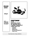
Caution:
Read and Follow
All Safety Rules
And Instructions
Before Operating
This Equipment
Sears,
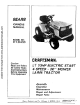
CRRFrSMRN
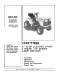
LT 12 HP ELECTRIC START
5 SPEED - 38" MOWER
LAWN TRA CTOR
•
•
Assembly
Operation
Maintenance
•
•
Repair
Repair
Roebuck
and Co,,
and Adjustment
Parts
Chicago,
IL
60684
U.S.A.
SAFETY
RULES
I.
2.
3.
4.
5.
6,
7.
8.
9,
10.
11.
12,
13.
14.
Know the controls and how to stop quickly. READ THIS
OPERA TOR S MANUAL and instructions furnished with
attachments.
Do not allow children to operate the machine. Do not
allow adults to operate it without proper instruction.
Do not carry passengers. Do not mow when children and
others are around.
Always wear substantial footwear. Do not wear loose fitting clothing that could get caught in moving parts.
Keep your eyes and mind on your tractor, mower and
the area being cut, Do not let other interests distract you.
Do not attempt to operate your tractor or mower when
not in the drivers seat.
Alwaysgetonoroffyourtractorfromtheoperator'sleft
hand side.
Clear the work area of objects (wire, rocks, etc.) which
might be picked up and thrown.
Disengage all attachment clutches before attempting to
start the engine.
Disengage power to attachments and stop the engine
before leaving the operator's position.
Disengagepowertomower,
stoptheengine, anddisconnect s_parkplug wire(s) from spark plug(s) before cleaning, making an adjustment, or repair, be careful to avoid
touching hot muffler or engine components.
Disengage power to attachments when transporting or not
in use.
Take all possible precautions when leaving the yah!de
unattended. Disengage the power-take-off , _ower the attachments, shift into neutral, set the parking brake, stop
the engine and remove the key.
Do not stop or start suddenly when going uphil! or
downhill. Mow up and down the face of slopes (not
greater than 150); never across the face, Refer to page
15. Reducespeedonslopesandmaketurnsgraduallytoprevent tipping or loss of control. Exercise extreme caution
when changing direction on slopes.
16 While going _p or down slopes, place Gear Shift Control Lever in 7st gear position to negotiate the slope
without stopping,
!7, Never mow in wet or slippery grass, when traction is unsure or at a speed whichcoufd cause a skid.
18. Stay alert for holes in the terrain and other hidden
hazards. Keep away from drop-offs.
19. Do not drive too close to creeks, ditches and public
highways.
20 Exercise spedal care when mowing araund fixed abjects
in order to prevent the blades from striking them, Never
deliberately run tractor or mower into or over any foreign
obiects.
21.
22.
Never shift gears until tractor comes to a stop.
Neverplacehandsorfeetunderthemower,
indischarge
chute or near any moving ports while tractor or mower
_
A_y_
clear of discharge chute.
23_ _re
whe_j_uEb'_ ]_ads or using heavy equipment.
I a ._, U_nly_E_pl_p_ea_drowbar
h;tch po;nts.
b.
c.
d.
24.
25.
26.
27.
28.
29.
Limit loads to those you can safely control.
Do not turn sharply. Use care when backing.
Use counterweight or wheel weights when suggested
in the owner's manual.
Watch out for traffic when crossing or near roadways.
When using any attachments, never direct discharge of
material toward bystanders nor allow anyone near the
vehicle while in operation.
Handle gasoline "with care - it is highly flammable,
a, Use approved gasoline containers.
b. Never remove the fuel cap of the fuel tank or add
gasoline to a running or hot engine or an engine that
has not been allowed to cool for several minutes after
running. Never fill tank indoors. Always dean up
spilled'gasoline,
c. Open doors if the engine is run in the garage - exhaust fumes are dangerous. Do not run the engine
indoors.
Keep the vehicle and attachments in good operating condition, and keep safety devices in place and wor'kin_l.
Keep all nuts, bolts and screws tight to be sure the equtp_
ment is in safe working condition.
Never store the equipment with gasoline in the tank inside a building where fumes may reach an open flame
or spark. Al!low the engine to cool before storing in any
enclosure.
30.
To reduce fire hazard, keep the engine free o _grass,
leaves or excessive grease. Do not dean prod_ ct while
engine
ts running
3 I. Except for adju/t_rl¢ _ J_O.,[qOT operate engine if air
cleaner or cover_j_i_t_O_r
ctwbu_etor air intake is
removed, RemovcWof _pa_cou_
_e_flre
hazard.
32. Do not operate without _-muffler_
tampe_with exhaust
system. Damaged mufflers or spor_ drte_te_ could create
a fire hazard. Inspect periodically and replace if
necessary.
33. The vehicle and attachments should be stopped and inspected for damage after striking a foreign object and
the damage should be repaired-before restarting and
operating the equipment.
34. Do not change the engine governor settings or overspeed
the engine; severe damage or injury may result.
35. When using the yah!de wl"thmower, proceed as follows;
a. Mow only in daylight or in good artificial light.
b. Shut the engine off when unclogging chute.
c. Check the blade mounting bohs Tor proper tightness
at frequent intervals.
36. Do not operate the mower without the deflector shield in
place.
37. Disengage power to mower before backing up. Do not
mow 7n ieverse unlessabsolutely necessary-an'd then only after careful observation of the entire area behind the
mower.
38.
Under normal usage the grass catcher bag material is subject to deterioration andwear. It should'be checked frequently for bag replacement. Replacement bags should
be checked to ensure compliance with the original
manufacturer's recommendations or specifications.
I
/k
I
JILL
CAUTION:
LOOK
IT MEANS-ATTENTION!
FOR THIS SYMBOL BECOME
TO POINTALERT!
OUT IMPORTANT
YOUR SAFETYSAFETY
IS INVOLVED,
PRECAUTIONS.
LOOK
FOR THIS
WORD
TO POINT
OUT
IMPORTANT
EQUIPMENT
PRECAUTIONS,
ii
I
ON OR NEAR ANY UNIMPROVED
FOREST COVERED,
BRUSH COVERED,
OR GRASS COVERED
LAND UNLESS THE ENGINE S EXHAUST
SYSTEM
IS EQUIPPED WITH A SPARK ARRESTER MEETING APPLICABLE
LOCAL WITH
OR STATE
LAWS (IF COMBUSTION
ANY). IF A SPARK
ARRESTER
IS USED,
SHOULD
THIS
UNIT IS EQUIPPED
AN INTERNAL
ENGINE
AND SHOULD
NOTIT BE
USED
|
I
|I
BE MAINTAINED
!
I,N EFFECTIVE
WORKING
ORDER
BY THE
OPERATOR.
In the State of California
the above is required by law (Section 4442 of the California
Public Resources Code), Other
states may have similar laws, Federal laws apply on federal lands. Refer to the Repair Parts Section, page 32.
CONGIIATULATK)NS
on your purchase of a Sears
Lawn Tractor. It has been designed, engineered and
manufactured to give you the best possible dependability and performance.
Should you experience any pro_
blem you cannot easily remedy, please contact your
nearest Sears Service Department. We have compete'nt, well-trained technicians
and the proper tools to
service or repair this unit.
SERIAL
NUMBER
DATE OF PURCHASE
THE SERIAL NUMBER WILL BE FOUND ON
THE MODEL PLATE UNDER THE SEAT.
MAINTENANCE
AGREEMENT
A Sears Maintenance Agreement is available on this
product. See the nearest Sears store or service center
for details.
CUSTOMER
YOU SHOULD RECORD THESE NUMBERS
AND KEEP FOR FUTURE REFERENCE,
RESPONSIBILITIES
Read and retain this manual. Study and observe the safety rules. Always use care when using your tractor,
Always keep your tractor and mower clean. Follow a regular schedule in maintaining,
caring for, and using
your tractor. A well cared for tractor will run better and last longer,
A TTACHMENTS
This unit can use many attachments now available at your Sears store. It cannot use attachments that engage
the ground like a plow, harrow, cultivator,
or tiller. See page 50 for a list of available attachments.
LIMITED
ON ELECTRIC
ONE YEAR WARRANTY
START RIDING EQUIPMENT
For one year from date of purchase,
when this riding equipment
is maintained,
lubricated,
and tuned up accor
ding to the operating and maintenance
instruction
in the owner's manual, Sears will repair free of charge any
defect in material or workmanship
in this electric start riding equipment.
This warranty excludes blade(s),
and become worn during normal
blade adapter(s),
use.
spark plug(s)
air cleaner
and belt(s),
which
are expendable
This warranty does not cover:
Tire replacement
or repair caused by punctures
from outside objects {such as nails, thorns, stumps,
or glass); and
- repairs necessary because of operator abuse or negligence,
including the failure to maintain the equipment according
to instructions
contained
in the owner's manual; and
- riding equipment
used for commercial or rental purposes.
FULL
90-DAY
WARRANTY
ON BATTERY
For 90 days from the date of purchase, if any battery included
with this riding equipment
proves defective
in
material or workmanship
and our testing determines
the battery will not hold a charge, Sears wifl replace the
battery at no charge.
WARRANTY SERVICE tS AVAILABLE BY CONTACTING
IN THE UNITED STATES. This warranty applies only
This warranty
to state.
gives you specific
SEARS,
ROEBUCK
legal rights,
and CO.,
THE NEAREST SEARS SERVICE CENTER/DEPARTMENT
while this product is in use in the United States.
and you may also have other
D/698-731A,
3
Sears
Tower,
rights
which
Chicago,
may vary from state
II 60684
INDEX
P
A
Adjustments:
Brake
...............
Carburetor
..............
Mower Drive Belt
Mower
Front-to-Rear
...........
Side-to-Side
...........
Throttle Control Cable
Engine Valves
...........
Air Filter
14
78
22
.....
Cleaning
................
Element ...............
Air Intake Screen, Eng ......
Assembly ...............
Attachments
..............
B
Battery:
Charging
...............
Cleaning
................
Installation
...............
Levels ..................
Preparation
...............
Starting
with Weak Battery
Storage
...............
Terminals
...............
Belt:
Motion
Drive Replacement
Mower
Drive Adjustment
Mower
Drive,
Remove/Replace
.......
Blade:
Sharpening
.............
Replacement
Brake Adjustment
.........
22
22
78
18
76
!6
76
5-B
50
7
15
8
t5
7
17
23
t5
t9
22
2 t
14
14
t4
C
Carburetor
Adjustment
Controls,
Tractor
...........
Cutting
Level, Mower
.......
18
9
12
E
Engine:
Air Screen ...............
Off Change
.........
Oil Level ...............
Oil Type ..............
Starting
................
Storage
.............
Valve Adjustments
........
t6
16
16
16
10
23
18
Type ...................
Storage .................
Fuse .....................
Hood Removal
H
.............
L
Levelling Mower Deck .......
Lubrication:
Chart ...................
Tractor Pivot Points .......
M
Maintenance
...............
Air Filter ................
Air Filter Element
.........
Air Screen
..............
Battery
.................
Blade Sharpening
Brake Adjustment
.........
Engine Oil ..............
Fuel Filter .............
Lubrication
Chart
Spark Plug
.............
Tire Care
.............
Mower:
Adjustment,
Front-to-Rear
Adjustment,
Side*to-Side
Blade Sharpening
.........
Blade Replacement
........
Cutting Level
............
Installation
...........
Operation
...............
Removal
.............
Muffler
..................
Spark Arrester
..........
F
16
18
10
23
20
22
24
17
13
16
16
16
15
14
14
16
18
24
18
14
23
22
t4
!4
!2
21
t 1
20
17
2
0
Oil:
Cold Weather Conditions
75
Engine .................
16
Storage
23
Operation
.............
9 t2
Operating
Your Mower
.....
t t
Operating
Your Tractor .....
7t
Starting
the Engine ........
1t
Stopping
Your Tractor
.....
10
Tractor Operation
on Hills
]2
Options:
Attachments
...........
50
Spark Attester ............
2
Filter:
Air ............................................
Fuel ..........................................
Fuel:
Type .................
Storage ..............
10
23
20
4
Parking Brake
Parts Bag ........
........
R
Repair and Adjustments
Blade .............
Carburetor
Fuse
........
Hood Removal
....
Motion Drive Belt
Replacement
......
Mower
Drive Belt
Replacement
........
Mower
Adjustment
Side-to-Side
....
Mower
Removal
9
5-6
14-24
. 15
18
20
20
10
20
22
20
S
Safety Rules .................
Seat .......................
Service Record ..............
Slope Guide Sheet ...........
Spark Plug .................
Speed Control Chert
.........
Starting
the Engine
..........
Steering Wheel
.............
Stopping
the Tractor
.........
Storage ....................
2
7
13
51
!8
12
I 1
5
10
23
T
Throttle Control
Cable
Adjustment
...............
Tires ......................
Trouble Shooting
Chart
18
14
25
......
V
Valves Adjustments
18
W
Warranty
Wiring {Schematic)
3
27
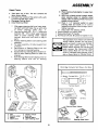
ASSEMBLY
UnpDck
Tractor
bushing.
Place steering wheel adapter on upper steering shaft.
9. With front wheels pointed straight ahead,
place steering wheel on steering wheel
adapter. Bars of steering wheel should point
straight across tractor.
10. Place 2 - 1/4" diameter washer on upper
steering shaft and install a 1/2" /ocknut
{washer and Iocknut found in bag of parts).
Tighten securely.
1 1. Snap insert into steering wheel.
e, Remove plastic on tractor hood.
f. Raise attachment
lift handle.
g. Roll Tractor off skid, Be careful of staples in skid.
8.
a.
Take items out of box. The box contains
the
items shown below,
b. Cut down four corners of the carton with a utility knife and fold down sides.
c, Disengage Parking Brake.
d. Install Steering Wheel
1.
2.
3.
4,
5.
6.
7.
Slide upper steering shaft over lower steer
ing shaft until bolt holes line up with slots
in
lower
steering
shaft
(Fig.
1).
Usetwohexbotts3/816x 1-1/4andtwo
Iocknuts
3/8 _ 16 to retain upper steering
shaft
to lower
steering
shaft.
Tighten
securely.
Bolts and nuts found in bag of
parts.
Position Steering Sleeve over steering shaft
assembly,
For easier assembly,
tilt tube towards
front
of tractor.
Place bottom
of Steering
Sleeve over two
front prongs on steering bushing,
Squeeze the two steering sleeve retainers inward to allow Steering Sleeve to pass over
retainers,
Push Steering Sleeve down aligning notch on
Steering
Sleeve
with
tab
on steering
The operation
foreign
which
of any tractor
objects
can result
Always
wear
safety
shields
before
starting
while
moving.
We
Vision
tacles
Safety
Mask
for
or standard
safety
able
Parts
at Sears
can result
Retail
Bag Contents
glasses
your
or
recommend
or Catalog
and
Wide
over the
glasses,
Not Shown
eye
tractor
spec _
avail-
Stores.
Ful! Size:
(21 Battery Carriage Bolts - 1/4-20 x 7-1/2
Terminal Guard
t5 ° Slope Instruction
@
Steering
a,
seat
b,
c.
d.
Steering
wheel
battery
battery acid
(2) Keys
Wheel Adapter
e, owner's
manual
f. parts bag
_.
Steering sleeve
upper steering shaft
And Instructions
5
in
thrown
into
the eyes,
in severe
eye damage,
.Steering Wheel Insert
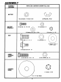
ASSEMBL Y
ASSEMBLY
PARTS
BAG CONTENTS
SHOWN
FULL SIZE
LOCATION
©
BATTER Y
(2) Lockwash_, 1/4 Int/Ext Tooth
(2) Wing
Nut, 1/4-20
©
BATTERY
TERMINALS
12) Hex Bolt, I/4
- 20 x 3/4
©
(2) Lockwasher
1/4
©
(2) Hex Nut, 1/4 - 20
(2) Washer 9/32 x 5/8 x 16 Ga,
©
F-
SEA T
(1) Hex Bolt, I/2 - 13 - x 1
(1) Lockwasher 1/2
m
(I) Washer 17/32 x I 3/16 x 12 Ga.
(1) Shoulder
bolt 5/16
- 18
©
"1
UPPER
STEERING
SHAFT
_HI]]]l]]ll]lllllllllll
{2) Hex Bolt 3/8 - 16 x 1 I/4
(2) Hex Locknut 3/8 - 16
STEERING
WHEEL
(1) Locknut, I/2-20
1/4" Dta. Washer
6
To assemble" tractor you
(21 7/16"
Wrenches
(1)
I/2"
Wrench
(2) 11/16" Wrenches
(1) 3/4"
Wrench
NOTE:
will need:
Tire Pressure
Screwdriver
Utllit V Knife
RIGHT HAND (R.H.! AND LEFT HAND
DETERMINED
FROM OPERATOR'S
WHILE SEATED ON THE TRACTOR,
WEAR EYE AND
ASSEMBL Y
Gauge
I 2
2
1/4
DIA
NUT
.
WASH_Ft
(LH.) ARE
POSITION
FACE SHIELD.
WASH HANDS
OR CLOTHING
IMMEDIA TEL Y IF ACCIDENTALLY
IN
CONTACT
WITH BATTERY ACID.
DO NOT SMOKE:
FUMES
FROM
CHARGED
BATTERY
ACID
ARE
EXPLOSIVE.
READ THE INSTRUCTIONS
INCLUDED WITH THE BATTERY VENT CAPS
IN THE BAG OF PARTS. ALWAYS
WEAR
GLOVES,
CLOTHING
AND
GOGGLES
TO PROTECT
YOUR
HANDS,
SKIN AND EYES.
STEERli
BUSHING
;TEERING
2.
Prepare
Battery
_/
Fill and charge battery
(before installing).
NOTE: SEE
DETAILED INSTRUCTIONS
PACKAGED
WITH BATTERY
VENT CAPS FOUND IN BAG OF PARTS.
a.
b.
c,
d.
e.
f.
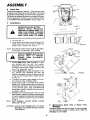
3.
Instafl
Seat.
STEERING
SLEEVE
RETAINER
k
SPraNG
\
SPRING
Seat position
should De adjusted
forward or backward
so that the operator can comfortably
reach Clutch, Brake
Pedal and safely operate tractor.
Fill each cell with battery acid. Add the acid until it reaches the bottom of the vent tubes (Fig,
3). Do not add the acid beyond this level or the
additional acid can come out when the battery
is charged.
After cells are filled, tilt battery
from side to
side to release air bubbles.
Allow battery to stand and settle for at least
thirty minutes,
If the level of acid falls below
the point described
in step (al, add more acid
until the correct level is reached. Install the battery caps, found in the bag of parts, to cover
the vent tubes. Wash the top of the battery
with water to remove any acid, then wipe dry.
Check battery case for leakage to make sure
that no damage
has occured
in handling.
Neutralize excess battery acid for disposal by
adding it to four inches of water in a five gallon
plastic container.
Stir with a wooden or plastic
paddle while adding baking soda until the addition of more soda causes no mf_re foaming,
It is recommended
that the battery be charged before use. Use a 12 volt battery charger.
Charge battery
at a rate of 6 amperes
for 1
hour.
NOTE:
OBSERVE
SAFETY
PRECAUTIONS, LISTED tN BOX ABOVE, REQUIRED
FOR BATTERY
CHARGING.
Check the acid
level after the battery is charged. If the acid has
fallen below the correct level, add distilled or
iron free water.
a.
Place seat on seat pan. Screw hex head machine
screw, iockwasher and flat washer into seat (Fig.
2). Screw shoulder bolt into seat (Fig. 2). Machine
screw, shoulder bolt and washers found in bag of
parts (shown full size on page 6).
b.
Tighten shoulder bolt using a 1/2" wrench. NOTE:
THE SHOULDER BOL T WILL BE LOOSE IN THE
SEA T PAN SL 07-.
c.
Tighten
washer
d,
Place seat in operating position. Sit on the seat
and press clutch/brake
pedal all the way down,
If operating position is not comfortable,
adjust
seat.
e.
To adjust: Raise seat. Loosen machine screw.
Slide seat to desired position.
Tighten machine
screw securely,
machine
screw, Iockwasher
using a 1/2"' wrench.
and ftat
I AIklLWASHER
MUST
BE TIGHTENED
SECUREI_MACHINE
SCREW-LOCKWASHER-FLAT
I
-LY
TO PREVENT MOVEMENT
OF SEAT.
7
Ill"
!
ASSEMBL Y
4.
Check Ttres
Check the a# pressure in the tires. Tires with too much
air pressure will cause the unit to ride rough. The wrong
air pressure will also keep the mower from cutting level.
The correct air pressure is shown on the side of the tires.
If the air pressure is not shown, set to pressures shown
in the REPAIR AND ADJUSTMENT
section (page 14).
5.
Install Battery
FIGURE 2
BEFORE INSTALLING BATTERY,
REMOVE
METAL
BRACELETS,
WRISTWATCH BANDS° RINGS, ETC.
FROM YOUR PERSON, TOUCHING
THESE ITEMS TO BATTERY TERMINALS COULD RESULT IN BURNS,
_'_jl
f
AWAy
BATTERY
GA P
VI{W
........
.,
VENT
_L_
L_IATTERY
TUaE
a. Lift seat (Fig. 2).
b . Lower battery into fender wel! with battery terminals toward front of tractor (Fig, 4). Make sure
battery
rests in battery
tray (Fig. 4).
NOTE:
BE SURE BATTERY DRAIN
ATTACHED
TO BATTERY
I
v_L
c{_ FIGURE3
TUBE IS SECURELY
TRAY DRAIN,
POSITIVETERMINALMUSTBECONSPARKS
FROM
NECTED
FIRST
GROUNDING.
ACCIDENTAL
TO
PREVENT
c.
Connect
RED battery cable to positive (+) battery terminal
with
hex bolt,
flat
washer,
Iockwasher and hex nut (shown full size on pg.
6) found in bag of parts. Tighten securely with
two 7/16"
wrenches.
(Fig. 4)
d. Connect BLACK ground cable to negative (-) battery terminal
with remaining
hex bolt, flat
washer, Iockwasher and hex nut (shown full size
on pg. 6) found in bag of parts. Tighten securely. (Fig, 4)
e. To prevent corrosion, apply grease to the battery terminals after installing cables.
f, Using the key hole on one side of the battery
support (Fig. 5) slide battery bolt into frame key
hole (head of bolt down). Fasten the battery bolt
to the terminal guard using internal/external
Iockwasher, wing nut, (shown full size on pg. 6)
as shown in Fig. 5.
g. Assemble the remaining battery
bolt to other
side of battery support and fasten terminal guard
to it with remaining internal/external
Iockwasher,
wing nut, (shown full size on pg. 6) as shown
in Fig. 5.
NOTE:
KEEP TERMINAL
ACCESS
DOORS
CLOSED
WHEN NOT IN USE,
CAUTION:
FIGURE 5
6.
DO NOT START ENGINE UNTIL YOU HAVE
REVIEWED THE OPERATION
SECTION OF
THIS MANUAL.
Maintenance
After
First
2
Hours
(Two
Mowing l
Changing oil after the first two hours (or two mowings)
will help eliminate
break-in residue which might be
damaging to your engine.
8
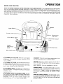
OPERA TION
KNOW
YOUR
TRACTOR
READ THIS OWNER'S MANUAL BEFORE OPERA TING YOUR LAWN TRACTOR. If you understand
the unit and its operation, you will achieve efficient
and peak performance
While reading the manual, compare the illustrations
with your
Lawn Tractor to familiarize
yourself with the location of various controls and adjustments.
Study the operating
instructions end safety precautions
thoroughly
to insure proper functioning
of your Lawn Tractor and to prevent injury to yourself
and others. Be sure to pay strict attention
to all warnings
and cautions:
they ar# included
for your safety. Save this
manual for future reference.
Ignition
Light
Switch
Throttle/Choke
Attachment
Lift Lever
Clutch
Brake
Pedal
t Clutch
Lever
Height
Adjustment
Knob
Gear Shift
_i
t
Lever
ATTACHMENT
CLUTCH LEVER: Push lever up to engage
attachment.
There will be an engine hesitation
as the
clutch
engages.
Parking
Brake
f2/
GEARSHIFT:
Press the clutch/brake
pedal down
and move gear shift lever to desired speed.
IGNITION: Place key in ignition
start. The switch
sprin 9 returns
ATTACHMENT
LIFT LEVER: Use the attachment
lift lever
to raise and lower the attachment
mounted to your trac
tot. Pull lever back slightly and push button,
then move
the lift lever forward
to lower attachment.
LIGHT
SWITCH:
Turns
ADJUSTMENT
KNOB: Use the
to adjust the mower height. With
in the "'up" position,
turn knob
raise
cutting
height
and
) to lower cutting
height.
THROTTLE/CHOKE
the headlights
CONTROL:
firmly
and turn to the right to
from the start positon,
PARKING BRAKE: To set the parking
clutch/brake
pedal completely
down.
brake lever in ,Engage"
position
and
from pedal,
Clutch/brake
pedal wilt
position.
CLUTCH/BRAKE
PEDAL: The pedal has 2 f_Jnctions; a
clutch and a brake, To engage the brake push the pedal
completely
down.
A TTA CHMENT HEIGHT
height adjustment
knob
the attachment
lift lever
clockwise
(F-_l
to
counterclockwise
(f-_
i,,,,
on and off.
brake, push the
Hold the parking
release pressure
remain
in brake
Use the throttle
control
to increase or decrease the speed of the engine, and to
choke the engine for starting.
Push lever to the right and
forward to choke.
9
OPERA TION
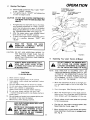
1.
Stopping
Your Tractor
NOTE: REMOVE KEY WHEN LEAVING
TO PREVENT UNAUTHORIZED
USE.
AIR
SCREEN
TRACTOR
a,
/
/
FUEL
•
FILLER
CAP
TANK
/
/
FIGURE
6
,
Push clutch-brake
pedal into full "'BRAKE'"
position.
Keep your foot on pedal.(Fig.7)
b. Place
attachment
clutch
lever
in
......
DISENGAGED
position.( Fi g; 7 )
,,
c, Move
gear shift
lever to
NEUTRAL
postion, (Fig.7)
d
Place parking brake in "'ENGAGED"
position and release pressure from clutch/brake.
Pedal should remain in "'BRAKE'" position.
(Fig.7)
e. Move
throttle
control
to "S'"
(slow)
position. (Fig,7)
f . Turn ignition key to "OFF"position.
Never
use choke to stop engine. (Fig.7)
Preparing The Engine
/
I
A
I
c3.
b.
LEARN TO START,
STOP ALARGE,
AND RE*
VERSEYOURTRACTORIN
OPEN AREA.
m I
This enginehasbeenahipped
f!lled with su
mer weight oi! (For cold weather operation
see
chart page 16). Check engine off level. Refer to
REPAIR AND ADJUSTMENT
section (page 16).
Fill fuel tank (Fig. 6), Use fresh, clean_ regular
unleaded gasoline.
Capacity
is 5 quarts.
FILL TO BOTTOM
OF GAS TANK
FILLER NECK.
DO NOT OVERFILL.
WIPE OFF ANY
SPILLED
OIL OR
FUEL. DO NOT STORE, SPILL OR USE
GASOLINE
NEAR AN OPEN FLAME.
CAUTION:
MOWER
CLUTE
8LADE
POSITION
NGAGED"
POSiTiON
HEADLIGHT
PARKING
BRAKE
"ENGAGED"
THROTTLE
"'--_CONTROL
_'LEVER
EXPERIENCE INDICATES
THAT ALCOHOL
BLENDED FUELS (CALLED GASOHOL
OR
USING ETHANOL OR METHANOL)
CAN AT
TRACT
MOISTURE
WHICH
LEADS
TO
SEPARATION
AND FORMATION
OF ACIDS
DURING
STORAGE.
ACIDIC
GAS
CAN
DAMAGE
THE
FUEL SYSTEM
OF AN
ENGINE WHILE IN STORAGE.
TO AVOID ENGINE PROBLEMS, THE FUEL
SYSTEM
SHOULD
BE EMPTIED
BEFORE
STORAGE
FOR 30 DAYS
OR LONGER.
DRAIN
THE GAS
TANK,
START
THE
ENGINE AND LET IT RUN UNTIL THE FUEL
LINES AND CARBURETOR
ARE EMPTY.
USE FRESH FUEL NEXT SEASON.
SEE
STORAGE
INSTRUCTIONS
FOR ADDITIONAL
INFORMATION.
POSITION
/
GEARSHIFT
LEVER
NEVER
USE ENGINE
OR CARBURETOR
CLEANER PRODUCTS
IN THE FUEL TANK
OR PERMANENT
DAMAGE
MAY OCCUR.
FIGURE
7
lO
I
3,
Starting
a'.
b.
d.
e.
I
4_
CAUTION:
OPERA TION
Engine
Move throttle control lever (Fig. 7) past "'FAST"
to the "CHOKE"
position.
Turn ignition key to "'START"
and release key
as soon as engine starts,
CAUTION;
c.
The
HEIGHT
ADJUSTMENT
KNOB
If engine does not start after four or five tries.
move throttle control lever to "'FAST" position,
wait a few minutes and try again. If the engine
does not start after four or five more tries, see
the TROUBLESHOOTING
Chart (page 25).
After
the engine starts move throttle
control
lever slowly
to the "SLOW"
position.
To start a hot engine move the throttle control
lever to a position
between
"FAST"
and
"SLOW".
i
/
DO NOT ADD ADDITIONAL
WEIGHT
TO
THE TRACTOR
OTHER THAN
THE OPTIONAL
WHEEL
WEIGHTS.
EXCESSIVE
WEIGHT MAY OVERLOAD
AND DAMAGE
THE TRANSAXLE.
FIGURE
.
Operating
1_ Read owner's
2. Know location
manual.
and function
OR
of all controls,
a,
6. Never carry children
or passengers.
7. Always
look behind machine
before backing.
8, Do t?ot mow where machine
can tip or slip.
9 ,, machine stops going uphill, stop blades and back
slowly
down.
! O. Be sure blades and engine have stopped before plac
ing hands or feet near the blades.
11, Remove key when leaving machine.
DEFLECTOR
SHIELD
IN PLACE]
THIS
TRACTOR
IS EQUIPPED
WITH
AN
OPERATOR PRESENCE SENSING SWITCH. ANY
ATTEMPT
BY THE OPERATOR TO LEAVE THE
SEAT WITH THE ENGINE RUNNING AND THE
ATTACHMENT
CLUTCH
LEVER
ENGAGED
WILL SHUT OFF THE ENGINE,
Move the attachment
lion and adjust height
Fig. 8.
the engine,
lift lever to the high pos_
of cut to mid range. See
Start
c.
Move the throttle
lever to mid range position.
Select a tow (_ st or 2nd) gear unlit you become
more familiar
with the operation
of the unit.
d.
11
THE
b.
BRAKE WILL HOLD
NEVER PLACE YOUR HANDS OR FEET IN
OR UNDER
ANY
POWERED
ATTACHMENT
OR NEAR ANY MOVING
PART
WHILE
TRACTOR
OR ANY
POWERED
ATTACHMENT
IS RUNNING
Tractor & Mower
DO NOT OPERATE THE MOWER WITHOUT
EITHER
THE
ENTIRE
GRASS
CATCHER,
ON MOWERS
SO EQUIPPED,
I
Keep guards, safety shield and switches
in place
and working.
Remove
objects that can be thrown by blades.
Do not mow when children and others are around.
MAKE SURE PARKING
TRACTOR
SECURE.
Your Lawn
8
!
I
|
NOTE:
A
LIFT LEVER
-'LOWEST
, POSITfOr_
OPERATION"
CAREFULLY FOR BEFORE
READ
THE
"RULES
SAFE
OPERATING
YOUR MOWER.
CAUTION
TO AVOID INJURY
4.
5.
CLUTCH
DO NOT RUN STARTER CONTINUOUSLY
FOR MORE THAN FIFTEEN SECONDS PER
MINUTE.
ALWAYS
WEAR SUBSTANTIAL
FOOTWEAR
AND
AVOID
LOOSE
FITTING
CLOTHING
THAT COULD GET CAUGHT
IN MOVING
PARTS.
q
ATTACHMENT
CLUTCH
LEVER "'DISENGAGED'"
POSITION
ATTACHMENT
LEVER"ENGAGED"
POSITION
Slowly release
to the mowing
(See Starting
clutch
area.
the Engine)
brake pedal
and proceed
e.
Stop the unit, then select a mowing
Speed Selection
Guide, page 12).
speed.
ISee
f.
Move throttle
lever to half throttle
and slowly
move attachment
clutch lever to engaged position, Fig. 8.
I
|
OPERA TION
g.
Slowly
h.
Move
i.
Observe
CAUTION:
release
throttle
clutch
lever
height
5.
NOTE:
brake pedal.
to fast position.
of cut and readjust
Mowing
Tips
TIRE CHAINS
CANNOT
MOWER ATTACHED.
BE USED
WI'PH THE
a,
Mower should be adjusted properly front to back
and side to side for good mowing performance.
Refer to REPAIR AND ADJUSTMENT
section
(page 22).
b.
Use the runner on the R.H. side as a guide; the
blade cuts approximately
an inch outside
the
runner (Fig, 8).
c,
Drive so that clippings
are discharged
onto the
area that has been cut. Have the cut area to the
right of the machine.
This wil! result in a more
even distribution
of clippings and more uniform
cutting.
d.
When mowing large areas (Fig. 9), start by turning to the right so that the clippings
will
discharge away from shrubs, fences, driveways,
etc. After two or three rounds, mow in the opposite direction
making
left hand turns until
finished.
e. If grass is extremely
taft, it should be mowed
twice. The first time cut relatively
high; the second time to the desired height.
f . The left hand side of mower should be used for
trimming,
g, See Speed Selection
Chart.
h.
Do not mow tall, dry (brown) grass over 6 inches tall. It is a fire hazard.
as desired,
BEFORE YOU MOVE
THE GEAR SHIFT
LEVER, COME TO A COMPLETE
STOP.
FAILURE TO DO SO CAN RESULT IN GEAR
BOX DAMAGE.
f
T
FIGURE
9
6.
Operating
The Tractor
On Hills
I
DO NOT DRIVE UP OR DOWN HILLS |
WITH SLOPES GREATER THAN 15 °
AND DO NOT DRIVE ACROSS ANY
SLOPE. REFER TO PAGE 51,
I
a.
b.
c,
Move gear shift lever to "" 1st" gear before star
ring up or down hills.
AVOID STOPPING
OR SHIFTING ON HILLS.
If slowing
is necessary,
move throttle
control
lever to slower position.
I
SPEED SELECTION
FUNCTION
GEARSHIFT
Normal
Mowing
2or
LEAVE ENOUGH ROOM WHEN STOPPING AND
STARTING
TO ALLOW
SLIGHT TRACTOR
ROLL DOWNHILL
AS CLUTCH-BRAKE
PEDAL MOVES
THROUGH
CLUTCH POSITION.
GUIDE
THROTTLE
3
d.
Heavy
Mowing
Snow
Blowing
Snow
I or2
1
e.
FAST
f.
|
I
If stopping
is absolutely
necessary,
push
clutch/brake
pedal quickly to brake position.
To restart tractor movement,
make sure tractor
is in the lowest speed range ("Ist'"
Gear) and
release clutch-brake
pedal SLOWLY.
Make all turns gradually.
Blade
7.
Transport
4-6
Transporting
Your Tractor
For pushing or towing your tractor, place Gear Shift Lever in
"iV" position. Do not tow or push at more than 6 MPH.
SLOWFAST
12
MAINTENANCE
To keep your tractor running better, longer, perform necessary
service
using the following
maintenance
schedule:
With
1.
2.
3,
Every
BEFORE MAKING ANY INSPECTION,
ADJUSTMENT, OR REPAIR:
1. PUSH CLUTCH/BRAKE PEDAL COMPLETELY DOWN.
2. MOVE'GEAR SHIFT CONTROL LEVER
TO NEUTRAL POSITION.
3. PLACE PARKING BRAKE IN "ENGAGED" POSITION. REMOVE FOOT FROM
PEDAL.
4, DISENGAGE ATTACHMENT CLUTCH
LEVER.
5. SHUT OFF THE ENGINE.
6. MAKE ABSOLUTELY
SURE THE
BLADES AND ALL MOVING PARTS
HAVE COMPLETELY STOPPED.
7. DISCONNECT THE SPARK PLUG WIRE
FROM THE SPARK PLUG AND KEEP
WIRE AWAY FROM THE SPARK PLUG
TO PREVENT INJURY FROM ACCIDENTAL STARTING. BE CAREFUL TO
AVOID TOUCHING HOT ENGINE OR
MUFFLER COMPONENTS.
Mowing
Make sure all nuts on bolts are tight and cotter pins
and retainer springs are secure.
Observe aft safety precautions,
Keep tractor
weft lubricated
(refer to page 17).
SERVICE RECORD
SERVICE
RECORD
Fill in dates
Blades
Brake
as you complete
Maintenance
SCHEDULE
regular
FIRST
EVERY
EVERY
EVERY
2
5
25
50
HOURS
HOURS
service
HOURS
HOURS
EVERY
1OO
HOUR_
Adjustment
Battery
Change
Engine
Check
Engine
Oil
Air Cleaner
Check
Muffler
Clean
Air
Clean
Front
_'_
Oil Leve_
Clean
Element
l_J
Screen
Lubricate
1_d
GrilI
Tractor
Replace
Spark
Replace
Air
Replace
Date
- sharpen
Check
Check
(Enter
Tire
Plug
Cleaner
I_
Eiement
Pressure
Fuel Filter
13
Performed)
REPAIR AND ADJUSTMENT
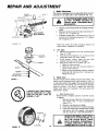
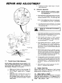
1.
Brake Adjustment
This tractor is equipped with an adjustable brake system
mounted on the right side of the transaxle
(Fig. !0).
I
IF TRACTOR REQUIRES MORE THAN I
SIX FEET STOPPING DISTANCE IN I
HIGHEST GEAR, THEN BRAKE MUST I
BE ADJUSTED.
a,
I
112
b.
(WITH PARKING
BPJ_K E ENGAGED)
c,
FIGURE
!0
Depress clutch/brake pedal and engage parking
brake.
Measure distance between brake operating arm
and nut "A"
on brake rod.
ff distance is other than l-l/2" loosen jam nut (Fig. 10)
and tum nut "A " until distance becomes 1-1/2", retighten
jam nut against nut "A"
Road test tractor for proper stopping
stated above, Readjust if necessary,
2,
ASSEMBLY
WASHER
FIGURE 11
A GRADE 5 HEAT TREATED BOLT
CAN BE IDENTIFIED
BY THREE
LINES ON THE BOLT HEAD AS
SHOWN AT LEFT.
tERS
l
distance
as
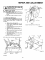
Tire Care
a . Maintain tire pressure in front at 14 PSi and rear
tires at 12 PSI.
b . Keep tires free of gasoline, oil, or insect control
chemicals
which can harm rubber.
c. Avoid stumps,
stones,
deep ruts and other
hazards that may cause tire damage.
d. Removing
wheel for tire repair (Fig. 12),
1 - Block up axle securely,
2 - Remove hub cap, klip ring and washer
to
allow wheel removal.
3 - Repair tire and reassemble,
Replace washers
and snap klip ring securely
in axle groove,
Replace hub cap.
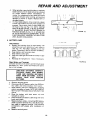
3.
Blade Care
For best results mower blades must be kept sharp, The
blades can be sharpened
with a few strokes of a file, or
on a grinding wheel. We suggest they be sharpened after
every 25 hours of mowing.
Do not attempt
to sharpen
while on mower.
If you mow in sandy soft check the
blades after each two mowings.
The sand wears the
blade away rapidly.
a. Blade Replacement
Raise mower
to highest position
to permit access
to blades.
1. Remove the hex head bolt, Iockwasher
and
flat washer
(Fig. 11) (turn counterclock
wise) ( F_).
2.
Remove and discard old blade.
3.
Clean top and bottom
of mower housing.
4.
Install new blade with SHARP EDGE DOWN
and secure with flat washer, Iockwasher
and hex head bolt, TIGHTEN SECURELY.
HUB
CAP
FIGURE 12
KLIP
RING
14
ALWAYS USE GRADE 5 HEAT TREATED BOLTS TO ATTACH
BLADES. DO
NOT USE PLATED
BOLTS.
CHECK
BOLTS IN BLADES OCCASIONALLY
TO MAKE SURE BOLTS ARE TIGHT,
TORQUE BOLTS TO 30-35 FT,-LBS.
i
I
REPAIR AND ADJUSTMENT
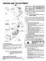
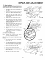
b .
c .
When grinding, care should be taken to maintain
blade balance and the blade should be checked
for proper
balance
before
reinstailation
on
mower. An unbalanced or bent blade will cause
excessive vibration
when running, and eventual
damage to mower or engine.
Replace bent or
damaged
blades.
To check blade balance, drive a nail into a beam
/
' I
i
or wail. Leave about one inch of the straight nail
exposed.
Place center hole of clean blade over
the head of the nail (Fig. 131. NOTE: CENTER
HOLE OF BLADE ON NAIL, IF BLADE IS PROPERLY BALANCED,
BLADE SHOULD
REMAIN
IN
POSITION SHOWN IN FIG. 13. IF EITHER END
OF THE BLADE MOVES DOWNWARD,
BLADE
IS NOT BALANCED. SHARPEN THE HEAVY END
UNTIL BLADE IS BALANCED.
4.
BATTERY
- °
BLADE
Rinse the battery
reinstall on tractor.
e .
Clean terminals and battery cable ends with wire
brush until bright.
Replace battery cables, connecting
RED battery
cable to positive terminal first, then BLACK battery cable to negative
terminal,
Coat terminal
connections
with grease after installation
of
cables.
Replace
with
plain
water,
dry
13.T_£A¥
CA,
Vt(W
-J
•
V[NT
TUBE
-_
]IATTE_Y
VEL
_LL
FIGURE14
Remove terminal
guard.
Disconnect
BLACK battery cable, then RED bat_
tery cable, and remove
battery
from tractor.
Wash battery
with four tablespoons
of baking
soda to one gallon of water. NOTE: BE CAREFUL
NOT TO GET THE SODA SOLUTION
INTO THE
CELLS.
d.
AWAy
L-----
LEAD-ACID
BATTERIES GENERATE
EXPLOSIVE GASES, KEEP SPARKS,
FLAME AND SMOKING MATERIALS
AWAY FROM SATTERIES. ALWAYS
SHIELD
YOUR
EYES
AROUND
BATTERIES.
g.
13
CARE
Clemn Battery, and Terminals
Corrosion and dirt on the battery and terminals cause
the battery to "'leak" power and hinders the opera
tion of the charger.
f .
i(
FIGURE
Et_T
c.
HOLE
j
Check Battery
a.
Battery acid solution level in each battery
cell
should be even with bottoms
of vent tubes in
cells (Fig. 14). Add ONLY distilled
or iron free
water if necessary,
NOTE: DO NOT OVERFILL,
b,
Keep battery and terminals
clean.
c.
Keep battery
bolts tight.
d.
Keep vent caps tight and small vent holes in caps
open.
e.
Recharge at 6 amperes for 1 hour if necessary.
a.
b.
CENTER
_'
and
terminal guard.
15
REPAIR AND ADJUSTMENT
• ,7 _
FUEL
W
_\
.20
6.
\
°
0 °
32 °
60 °
80 °
100 °
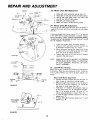
Check
Engine Oil Level
NOTE:
DO NOT CHECK ENGINE OIL LEVEL WITH
ENGINE RUNNING,
CAP
Several minutes after stopping engine, check engine oil
level with tractor on level ground, yVipe dipstick (Fig. 15)
clean, screw it down tight for a few seconds, remove
and read oil level. If necessary,
add oi! until "'FULL" mark
is reached.
(See chart
above).
NOTE:
DO
NOT
OVERFILL,
FIGURE15
ENGINE OIL
FILLER CAP
AND DIPSTICK
7.
AIR CLEANER
COVER
Clean Air Cleaner Element (Fig. 16)
a. Remove two cover knobs and remove air cleaner cover.
b.
Remove foam pro-cleaner.
-Wash pro-cleaner in liquid detergent and warm water to
remove dirt.
---
AIR
SCREEN
FOAM
ELEMENT
/
/
8.
AIR
NER
FIGURE
J
Clean Air Screen and Engine Cooling Fins.
|
BODY
ALWAYS
WEAR EYE AND FACE |
PROTECTION
WHEN USING COM-]
PRESSED
5.
Change
Engine Oil
The best time to change engine oil is at the end of a day's
operation when all dirt and foreign materials are suspended in the hot oil.
Capacity
is 1-1/2 quarts.
NOTE: DO NOT OVERFILL,
Dipstick
assembly must be securely tightened
into tube
at all times when engine is operating.
CAUTION:
Wrap pro-cleaner in cloth and squeeze dry.
Wipe foam with a light coat of engine oil. Do not saturate,
squeeze in rag or towel to remove excess oil.
c. Remove two nuts from top of cartridge,
d, Removecartridgeandcleanaircleanerbodycarefullyto
prevent dirt from entering carburetor,
e. Clean cartridge by gently tappmg on flat sudace, ff very
dirty, replace cartridge.
f.
Reassemble air cleaner.
NOTE: Nuts holding air cleaner cartridge must be installed with
fiber washers down on cartridge plate to prevent dirt from
entering carburator, T_hten nuts by hand, Overt_htening
could collapse cartridge.
NOTE: NEVER RUN ENGINE WiTH AIR CLEANER REMOVED.
a.
b.
c,
TO AVOID DAMAGE TO THE STARTING SYSTEM, USE SAE 5W30 OIL
WHEN THE TEMPERATURE
FALLS
BELOW 32 ° .
d.
e.
f.
Recommended
SAE Viscosity
Grades
Determine temperature
range expected before next off
change. All oil must meet A.P.I. service classification
SD,
SE or SF.
AIR.
/
Air screen and cooling fins (Figs. !6 and 1 7) must be
kept free of dirt and chaff to prevent engine damage from
overheating.
Clean with a wire brush or compressed
air
to remove dirt and dried gum fibers.
Remove hood (page 20).
Snap off air cleaner cover (Fig. 16).
Remove 3 screws securing air cleaner body (Figs. 16
and 17) and remove,
(Cover carburetor to prevent
entry of dirt.)
Remove oil dipstick
and cover opening to prevent
entry of dirt.
Remove 3 screws from blower housing and rift housing off engine (Fig, 17).
Use compressed
air or stiff bristle brush to thoroughly
clean engine cooling fins (Fig, t 7) and air screen (Fig.
16).
g. To reassemble,
reverse above procedure•
h . Be certain carburetor tube, breather tube, and gaskets
are in place (Fig. 1 71,
16
REPAIR AND ADJUSTMENT
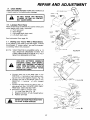
9.
Check
Muffler
Inspect and replace damaged
it could create a fire hazard
muffler and/or deflector
and/or damage.
as
I
DO NOT
TOUCH
HOT
CYLINDER
OR FINS AS
MAY CAUSE BURNS.
10.
Lubricate
Pivot Points
Place several drops of SAE 30 oil at points
move against each other, expeeially:
a. Front axle pivot
b. Hood hinges
c. Foot pedal shaft (both ends)
d. Lift shaft (both ends)
See Lubrication
Chart
page
MUFFLER,|
CONTACT
I
where parts
GASKET
24.
1 1. Starting
your Tractor
With a Weak Battery
If your battery is too weak to start the engine, it should
be recharged./f
"'jumper cables" are used for emergency starting,
follow this procedure:
NOTE:
YOUR TRACTOR
IS EQUIPPED WITH A 12
VOLT NEGATIVE
GROUNDED
SYSTEM. THE
OTHER VEHICLE MUST ALSO BE A 12 VOLT
NEGATIVE
GROUNDED
SYSTEM.
LEAD-ACID
BATTERIES GENERATE
EXPLOSIVE GASES. KEEP SPARKS,
FLAME AND SMOKING MATERIALS
AWAY FROM BATTERIES. ALWAYS
WEAR EYE PROTECTION
WHEN
AROUND BATTERIES.
a.
b.
c,
d.
Connect
each end of the RED cable to the
POSITIVE
(+) terminals
of each battery
(taking care not to short against chassis).
(Fig. 18)
Connect
one end of the BLACK cable to the
NEGATIVE
(-) terminal
of fully
charged
battery.
Connect the other end of the cable to the L,H,
side panel bolt (Fig, 19) NOTE: KEEP AWAY
FROM GAS TANK AND BATTERY.
Disconnect
cables in reverse order:
1 . LH. side Panel Bolt (Fig, 19)
2. Negative terminal
of fully charged battery
3. Positive terminals
/
/
17
REPAIR AND ADJUSTMENT
d.
13.
If holes do not align,
cable adjustment.
Carburetor
NOTE:
steps
in thr, ottle
adjustment
ADJUST THROTTLE CONTROL CABLE
BEFORE MAKING ANY ADJUSTMENT
TO CARBURETOR.
a, Withengineoffturnhighspeedmixturescrewc/ockwise ("'_)
closing finger tight ONL Y, and turn
counterclockwise
(_"_,)
I-3/_ turns (Fig. 20).
THROTTLE
LEVER
I
HOLES
repeat
*'A"
/
NOTE: THE SCREW
BY TURNING
-PLATE
b,
SEAT MAY BE DAMAGED
IT TOO FAR CLOCKWISE.
Turn idle mixture sere w clockwise
("'_)
closing
finger tight only, and turn counterclockwise
(_")
1-½ turns (Fig. 20),
Start engine and allow to warm for five minutes.
Make final adjustment
with engine running and
Gear Shift lever in "'NEUTRAL'" position.
With throttle
control lever
turn high speed
mixture
( "_-_)
until engine runs
counterclockwise
{'_--_ ) _
e,
JDLE
MIXTURE
FUEL
SCREW
_= FUEL
HIGH SPEED
MIX_FURE
i
FILTER
LINE
CLAMP
FIGURE 20
in "'FAST" position,
screw
clockwise
"rough"
then turn
turn.
With throttle
control lever in "'SLO W'" position,
turn /die mixture
screw
counterclockwise
(_""_)
until engine runs "rough°" and then turn
clock wise ('-'_) until engine begins to die. Turn
idle mixture
screw to a point midway between
these positions.
SCREW
030"
f. With throttle
control lever in "'SLO W'" position,
engine should idle at 1700 RPM. If engine idles
too slow, push throttle
control lever above idle
and turn idle speed screw one turn clockwise
('-_),
Set throttle controllever
at "'SL 0 W", Repeat until satisfactory
idle is attained.
FEELER
GAUGE
g.
FIGURE 21
1 2,
Throttle
Control
Cable
Adjustment
DO NOT MAKE UNNECESSARY
ADJUSTMENTS.
FACTORY SETTINGS ARE SATISFACTORY
FOR MOST APPLICATIONS
AND CONDITIONS.
IF ADJUSTMENTS
ARE NEEDED, PROCEED AS FOLLOWS,
a.
b,
c,
h.
If engine idles too fast with throttle control
in "SLOW"
position push throttle
control
above idle and turn idle speed screw one
counterclockwise
(_"_ ), Set throttle control
at "'SLOW".
Repeat until satisfactory
idle
tained.
High speed stop is factory adjusted.
ADJUSTDAMAGE
MAY RESULT,
lever
lever
turn
lever
is at-
DO NOT
1 4.
Replace
Spark Plug
Replace spark plug at the beginning
of each mowing
season or every 100 hours, whichever comes first, Gap
should be set a 0.030 inch (Fig, 21).
Make sure air cleaner is clean (see page 16)_
With engine not running,
place throttle
con
trol in "'FAST"
detent
(not in "CHOKE"
position),
Check that hole in throttle
lever and hole in
1 5. Adjust Vatves on Engine
After approximately
200 hours of operation, the engine
valves will require adjustment.
It is suggested that a
Sears Service Center do this work, Correct settings are:
Intake _ .002, Exhaust - .004.
plate line up (Fig. 20 - Insert),
tf holes "',4"
are not aligned, loosen clamp screw and move
throttle cable until holes are aligned. Tighten
clamp screw.
18
REPAIR AND ADJUSTMENT
ENG}NE
PULLEY
LEAKS AND THAT HOSE CLAMPS
BE SURE INSTALLED.
THERE ARE NO FUEL
PROPERLY
I • _k
/
DRIVE BELT
INSTALLATION
DECAL
ARE
LINE I
CLUTCH
16.
Replace
In-Line Fuel Filter
If fuel filter is clogged, obstructing
fuel flow to carburetor, replacement
is required.
a.
With engine cool, remove fitter and plug fuel line
sections which were remove(Jfrom both ends of fuel filter
(Fig. 20),
b.
Place new fuel filter in position
in fuel line.
PULLEY
L,H.
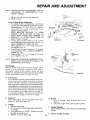
1 7. Motion Drive Belt Removal
The tractor drive belt may be replaced without tools. Park
the tractor on level area, Engage parking brake. NOTE:
A BELT INSTALLATION
DECAL iS UNDER LEFT
FOOTREST.
SIDE
BELT GUIDE
a.
b.
Remove mower. (See page 20).
Remove two retainer springs from belt guide
bracket
below
transaxle
pulley,
Remove
bracket (fig. 22).
c . Swing belt guides away from belt, toward rear
of tractor
(Fig. 22).
d. Roll belt over top of transaxle
pulley.
e, Roll belt over engine pulley and off idler (Fig,
23),
f . Release parking brake. Pull belt as far as possihie over top of clutch pulley.
g.
Reset parking
brake. Pull belt over top of
clutch pulley (Fig. 23).
h.
Pull belt out through shift gate to remove from
tractor
(Fig. 24).
Install belt by reversing
above procedure,
REAR
VIEWED
FROM BOTTOM
OF TRACTOR
FIGURE 23
NOTE: REPLACE ONLY WITH BELT LISTED IN MANUAL.
BELT
GUIDE
TRANSAXLE
PULLEY
SH_FT
GATE
FIGURE
/
_ I
RETAINER
BELT
SPR_NG
BRACKET
GUIDE
RETAINER
SPRING
FIGURE2 2
19
24
REPAIR AND ADJUSTMENT
18. Fuse Replacement
Replace with 30 amp automotive
- type plug-in
fuse holder is located under the dash.
fuse. The
1 9, Hood Removal
a.
To raise hood,
lift
b.
To remove hood, grill and side panels, raise
hood and loosen one screw on each side panel.
(This screw remains in the side panel) (Fig. 25).
c.
Unsnap
d.
Stand in front of tractor.
forward
and lift off (Fig.
e.
To reinstall,
headlight
at rear of hood,
connection
(Fig. 26).
Grasp
26).
hood
and
tilt
reverse above procedure.
SCRfW
20.
_IGURE25
/
NOTE:
CLUTCH
ROD
REAR
SUSPENSION
TRUNNIONS
LIFT
BRACKET
FIGURE27
20
Mower
Removal
a,
Remove
"'Mower
mower
belt per instructions
Drive Belt Removal"
through
under
step(c).
b,
Remove retainer
spring
clutch rod out of clutch
C,
Pull retainer springs out of rear suspension
nions. Remove rear suspension
trunnions
lift brackets
(Fig, 27).
d.
Pull retainer
spring
out of
Remove rear hinge pin. (Fig.
e,
Pull retainer
spring
Remove front hinge
f.
Use lift lever to raise suspension
mower
out from under tractor,
from clutch rod; pull
bracket.
(Fig. 27)
trunfrom
rear
27)
hinge
pin.
out of front
pin (Fig. 27).
hinge
pin.
arms,
Slide
IF AN ATTACHMENT
OTHER
THAN
THE
MOWER DECK IS TO BE MOUNTED
ON THE
TRACTOR,
THE L.H. AND R,H, SUSPENSION
ARMS ( FIG. 27) SHOULD BE REMOVED FROM
TRACTOR.
REPAIR AND ADJUSTMENT
21.
Mower
Installation
Your Mower
installs without
the use of tools. Raise Attachment Lift Lever (Fig, 28) to its highest position,
Turn
height adjustment
knob to lowest position
(Fig. 29).
a.
Slide Mower
R.H. Side.
under
tractor,
discharge
ATTACHMENT
CLUTCH
LEVER
-OISENGAGED
POSITION'*
guard to
LIFT LEVER
LOWEST
J POSIT_ON
b . Install front hinge pin through axle and parallel
rink (Fig, 30). Secure with retainer spring.
c.
Install
rear hinge
pin through
mower
brackets and parallel link (Fig. 30). Secure
retainer spring.
d,
Install
e,
Move Attachment
rift lever (Fig. 28) forward
to lower
suspension
arms.
Sfide trunnions
through rift bracket holes and secure with retainer springs (Fig. 27),
f .
clutch
rod in clutch
lever
(Fig.
lift
with
FIGURE 28
30).
ENGINE
\\
!BELT
Roll belt over engine pulley. Make sure belt is
inside
belt guides
(Fig. 29), See belt drive
schematic
decal on mower
housing,
PULLEY
\
\
!
22.
g,
Use Attachment
mower.
h,
Turn height adjustment
knob clockwise
(/"_1
to the middle of its travel, or to desired cut
height (Fig. 29).
Mower
NOTE:
REPLACE
MANUAL,
lift
lever
(Fig.
28)
!
to raise
Drive Belt Removal
MOWER
LOCATED
ONLY
BELT
INSTALLATION
ON MOWER HOUSING.
WITH
THE BELTS
SPECIFIED
DECAL
IN THIS
a.
Place attachment
clutch
position
(Fig. 281.
b.
Turn height adjustment
tion, Move Attachment
ward to lower mower
c.
Roll belt off
engine
d.
Pull belt
both
e,
Spring bett guide away
belt off idler pulley.
from idler pulJey and pull
f.
Slide
extension
belt
off
from
lever in "Disengaged"
CLUTCH
ROD
knob to lowest posilift lever (Fig. 28) forto its lowest position.
pulley
mower
under
FIGURE 29
(Fig.
deck
29).
pulleys.,
spring.
HINGE
PiN
FIGURE 30
21
REPAIR AND ADJUSTMENT
23.
Mower
DHve Belt Replacement
a. Slide belt under extension
spring (Fig. 31).
b . Place belt on rear side of both mandrel pulleys.
c, Spring idler belt guide down and place belt
around rear side of idler pulley.
d. Roll belt over engine pulley.
e, Make sure belt is inside all belt guides.
24.
Mower
Drive Belt Adjustment
Your tractor has been manufactured
with the ability to
readjust the mower belt drive to provide you with longer
belt life.
If the attachment
clutch lever travels 3- 1/2" up the slot
in the dash before spring resistance
is evident,
adjust
ment is necessary.
NOTE: CHECK FOR PROPER SPRING
TENSION WITH THE ENGINE OFF AND THE LIFT LEVER
IN THE HIGHEST POSITION.
EXTEN
SPRING '_
RH
PIVOT
BRACKET
a.
b.
ROD
BOLl
J
c,
L H PtVOT
BRACKE_T
FIGURE31
_
d.
_%
NOTE:
LIFT
LEVER
LEVER
PLUNGER
_._
soTroM :_
OFCURL,
WHEN INSTALLING
A NEW BELT, EXTENSION
SPRING MUST BE RETURNED TO LOWER END
OF SLOT {ORGINAL
POSITION)
ON ROCK
SHAFT ASSEMBLY.
r
25.
Level Mower
Housing
Adjust the mower while tractor is parked on level ground
or driveway.
Make sure tire pressures correct. If tires are
over or under inflated,
you will not properly
adjust your
mower.
--P-_:_. BOTTOM
_p--__==x._._-q[,/
_oFcurl
u.E
:ouNo
FIGURE32
I
NUT
SIDETO
SIDE
ADJUSTMENT
TRUNNION
Lower the mower
deck for easier access
Using (2) 7/16" wrenches,
remove the bolt, nut
& D-shaped
washers
(Fig, 31 - Inset).
Move extension
spring from lower end of slot
to upper end in rock shaft assembly
and install
bolt, nut & the D-shaped
washers.
Tighten bolt and nut to secure the D-shaped
washers
(fiat side down).
"'C"
-B..
FIGURE33
22
Side-to-Side
Mower Adjustment
a. Depress lift lever plunger and use lift lever to
raise mower
to maximum
cutting
height,
b, Measure height from bottom of curl to ground
line at front of mower. Distance "'A "" should be
the same on both sides (Fig. 32).
c. If distance
"A '" needs to be changed, snap out
access hole cover on L.H. side above footrest,
Use 11/16" wrench
on nuts "'B'" and "C" at
side-to-side
adjustment
trunnion
(Fig. 33).
d. To raise left side of mower, loosen nut "'B" and
tighten nut "C".
e, To lower left side of mower, loosen nut "'C" and
tighten nut "'B'.
REPAIR AND ADJUSTMENT
NOTE:
ONE R()TATION OF ADJUSTMENT
NUTS IS
EQUIVALENT
TO APPROXIMATELY
3/16"
HEIGHT CHANGE.
REAR
f,
g.
Be sure all nuts are securely
Replace cover.
tightened.
SUSPENSION
ARM
/
Front-To-Rear
Mower Adjustment
a.
To obtain the best cutting results,
your mower
housing should be adjusted so the front and rear
flange distance
"D'" (Fig. 34) is 1/2" lower in
front
when the mower
is positioned
in the
highest
cutting
position.
NOTE:
MEASURE
DISTANCE
"D"
FROM
GROUND
LINE TO BOTTOM
OF CURL ON
RIGHT
REAR FLANGE
AND
COMPARE
TO
DISTANCE
"D"
AT BOTTOM
OF CURL ON
RIGHT FRONT FLANGE.
b. To raise rear of mower, loosen nut "'E'" on both
rear suspension arms. Screw both nuts "'F'" up
EQUAL NUMBER OF TURNS (Fig. 35).
When distance
"'D'" is I/2" lower at front than
C.
rear tighten nuts "E".
d.
To lower rear of mower, loosen nut "F" on both
rear suspension
arms an EQUAL NUMBER OF
TURNS (Fig. 35).
When distance
"'D'" is 1/2" lower at front than
a.
rear, retighten
nuts "E".
NOTE:
LINE
GROUND
LINE
REAR
SUSPENSION
TRUNNION
FIGURE 34
/
REAR
SUSPENSION
NUTE
R£AR
SU_ENStON
TRUNNION
"_
WHEN ADJUSTING
REAR SUSPENSION
TRUNNIONS, ALWAYS ADJUST BOTH EQUALLY SO
MOWER WILL STAY LEVEL.
ARM
LIFT
BRACKET
NUT"F'
26, Storage
Remove mower from tractor
for winter storage,
When
mower
is to be stored
for a period of time, clean it
thoroughly,
remove all dirt, grease, leaves,
etc. give
blades and underside of housing a good coat of grease
or rust preventative.
Store in a clean dry area.
A,
Fuel System
It is important
to prevent gum deposits
from forming in essential
fuel system parts such as the carburetor,
fuel filter, fuel hose, or tank during storage.
Also, experience indicates that alcohol blended fuels
(called gasohol or using ethanol or methanol)
can at
tract moisture
which leads to separation
and formation of acids during storage. Acidic gas can damage
the fuel system of an engine while in storage,
To
avoid engine problems,
the fuel system should be
emptied
before storage
of 30 days or longer.
B.
Engine Off
Drain (with engine warm) and replace"
engine oil, (See chart page 16).
C*
Cylinder
1. Remove spark plug.
2. Pour one ounce of oi! through
to cylinder.
3, Turn ignition key to "START"
seconds
to distribute
oil.
4.
Replace
with
new
spark
plug.
with
FIGURE 35
clean
spark plug hole inposition
D,
Battery
1. Prior to storage,
clean terminals
and top of
battery
2. Disconnect
cable from positive side of battery.
E.
General Cleaning
Clean engine, battery,
matter.
seat,
for a few
F.
23
Store in a clean,
dry area.
finish,
etc. of all foreign
REPAIR AND ADJUSTMENT
LUBRICATIONCHART
AXLE
PIVOT
(_
SPINDLE
_
FRONT
BEARING WHEEL
_
,_
_FRONT WHEEL
BEARING
ENGINE
CLUTCH
PIVOT
l_J
CLUTCH/BRAKE
PIVOT
CLUTCH/BRAKE
PIVOT
_
A
TTACHMENT
ARM
LIFTATTACHMENT
LIFT ARM
1_
MOWER CLUTCH
PIVOT
SAE 30 MOTOR OIL
_GENERAL
(_
24
PURPOSE GREASE
REFER TO PAGE 16 FOR ENGINE
OIL SPECIFICATIONS.
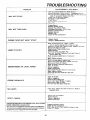
TROUBLESHOOTING
PROBLEM
CAUSE/REMEDY
Push
Clutch/Brake
Pedal
into
(SEE INDEX)
Brake
Position
Move
Attachment
Clutch
Leve_ to "Disengaged
Fill Fuel
Tank with
Gasoline
Check
Fuel Line
{clean
if necessary)
Replace
Fuel Filter
Check
fuse for fault and replace
• WILL NOT START
and
Po_ition
Carburetor
Recharge
or replace
Battery
*
Check
Wiring
Rep;ace Spark Plug a_d asl, ust DaP
Ao/ust valves
WILL NOT TURN
Charge Battery
Replace Ignition Switch
Depress Clutch/Bt_ke
Pedal
Disengage
Attachment
Clutch
Replace InteHock Switch
Replace Solenoid
Replace Fuse
Check Aft Wire Connections
OVER
Replace
ENGINE
HARD
CLICKS
BUT WON'T
START
Lever
Starter
Char_ or Repine Battery
Place Throttle Control in "'FAST" position
and run starter several times to clear out gas
Remove and clean Fuel Tank end lines. Replace Fuel Filter
Remove Air Filter and clean
Replace Spark Plug and adjust gap
Replace Battery
Check the wiring end Spark Plug
Drain Fuel Tank and Carburetor.
use fresh fuel and
replace Spark Plug
Make necessary
adjustments
to Carburetor
TO START
Major
Engine
Overhaul
Shift to a lower gear o_ reduce load
Remove and clean Fuel Tank; replace
Remove and clean Air Cleaner
ENGINE
MISSES
ENGINE
Make
Clean
OR LACKS POWER
Clean Air Screen
Add ot change o_t
Clean Engine Cooling Fins
Remove and clean Muffler
or t_place
Remove and clean Air Filter
Use fresh fuel and edjust Carburetor
OVERHEATS
Check Fuse. Switch
Headlight
Bulb5
and
wire connections
Repiace
Check
Fuse and replace
Replace Battery
Replace
Regula tot
Reolace Alternator
CHARGE
OPERA TOR PRESENCE
SYSTEM
WILL NOT SHUT
DOWN
WHEN
OPERATOR
LEAVES
SEAT.
Note: This _acter is equipped with an operatorpresenc, e senstt_eyslem.
Any attempt by the operator to lave the seat with the engine running and
the attachment
adjustments
Add or change oil
Replace Spark Plug
Check Spa_k Plug and check for loose wires
Major Engine OVerhaul
Drain Fuel Tank and Carburetor
and refill
NO LIGHTS
WON'T
necessary
carburetor
Ai, Screen
Fuel Filter
clutch engaged wiil shut down the engine.
25
Engage
Check
attachment
clutch
ell wire connections
Check
Check
seat
PTO
switch
Switch
Check
operator
presence
relay
TROUBLESHOOTING
Place
Check
Throttle
Control
in *'FAST"
air pressure
in tires
Check
front
merit
UNSATISFACTORY
MOWER PERFORMANCE
UNEVEN DISTRIBUTION
OF CLIPPINGS
Usa
to rear
a slower
ground
Check
engines
Rep4ace
mower
Reinstafl
Replace
Re-adjust
and
RPM's
blades
side
portion
re side
mower
adjust
speed
{refer
to
mower
blades
with
with proper
mower
mower
drive
belt
Carburetor
top of
blades
blade
Adju_tmentl
up
install new Mower Drive Belt
Reinstall Mower Ddve Belt
MOWER
BLADES
EXCESSIVE
WILL NOT ROTATE
MOWER
VIBRATION
WIND ROWING STRIPPING
OF GRASS CLIPPINGS
UNEVEN
Adjust Mower Drive Belt
OR DROPPING
Replace
Replace
Frozen
Frozen
Mandrel
Idler Pulley
Replace
Replace
Bent or Unbalanced
Mandrel,
Straighten
Blades
Deck or replace
Let grass dry out
Clean underside
Readjust Mower
CUT OR SCALPING
Readjust Mower
26
of Mower
Deck
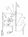
12 H.P. 38" RIDING
LAWN TRACTOR
- - MODEL NUMBER
917.254622
SCHEMATIC
12V
_°
ollllo
°_
[O_
RED
INTERLOCK
SWITCHES I
ATT MENT CLUTCH
CLUTCH/BRAKE
(PEDAL UP)
,CLUTCH
OFF)
__
$ WHITE
I
I
S
I
I
I
!
1
_
IGNITION
SWITCH
FUSE
L
T
OB
30 AMP
G
IGNITION SWITCH
;POSITION
CIRCUIT
OFF
M-G
ON
B-L
START
B-S
_
/
BLACK
,No_wI;_;,E
BLACK
O
SPARK
BLACK
L
I
SOLENOIDI
BLACK
M(
I
PLUG
DIODE
RED
_]
_
3 AMPS DC
AT 3600 RPMo BATTERY
ORANGE
CHARGING
COIL
20 VOLTS
IN LINE
AC (MINI
BROWN
LIGHT
SWITCH
O
<
WIRING INSULATED CLIPS
NOTE: IF WIRING INSULATED CLIPS
OR TIES WERE REMOVED FOR SERVICING OF UNIT. THEY SHOULD BE
REPLACED TO PROPERLY SECURE
YOUR WIRING.
27
CHASSIS
GROUND
U
\
\
\
2g
m
30
31
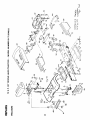
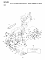
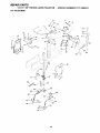
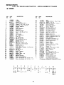
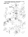
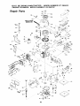
REPAIRS
12 H.P. 38"
RIDING
LAWN
TRACTOR
- - MODEL
NUMBER
917.254622,
DRIVE
HH
K
L
6\
63
19 {
66
-43
6581
_'_55
27
_75
22
62
18
2
30
57
3_
_
59
55
88
/
58
72
65
Spark
OPTIONAL
34
32
Attester
EQUIPMENT
t
REPAIR PARTS
,12
H.P.
38"
RIDING
LAWN
TRACTOR
- - MODEL
NUMBER
917.254622
DRIVE
KEY
NO,
PART
NO.
t
123088X
2
3
4
5
6
7
8
9
10
!1
12
13
14
105731X
120374X
STD551143
74770720
120302X
!08835X
2949R
101326L
71070510
STD551131
10120OK
2751R
17490628
15
16
STD551125
122372X
17
18
19
20
21
22
23
24
STD523727
73680600
STD580025
105703X
12000028
109167X
STD523710
17490512
25
26
27
28
29
30
31
32
33
34
35
36
37
38
39
4O
41
42
108171X
109368X
4921H
106190X
STD523107
73680500
109370X
109369X
STD523707
121748X
!06933X
105699X
71040412
106362X
STD561210
19151216
104777X
17490612
43
44
19131312
10573OX
A
DESCRIPTION
KEY PART
NO, NO.
Engine, 12 HP, Tecumseh
Model No. 143.396132
Pulley, Engine
Valve, Drain Oil
"Washer, Lock' 7/16
Bolt, Hex 7/16-20 x 1 !/4
V-Belt, Drive
Muffler
Gasket
Deflector, Muffler
Hex Hd. Cap Screw 5/16-18 x 5/8
*Washer, Lock 5/16
Spacer
Clip
Screw, Hex Washer Thd. Rolling
3/8-16 x 1-3/4
Bolt, Hex 3/8-16 x 2-3/4
Transaxle Tecumseh,
5 Speed, Model
143.920037
(see pages
parts breakdown)
* Bolt, Hex 3/8-16
× 2-3/4
Nut, Crownlock
3/8 16
40 and
* Key, Woodruff
No. 9 3/16
Pulley, Transaxle
Ring, Retainer
Bracket
Transaxle
*Bolt,
Hex 3/8-16
x 1
Screw,
5/16-18
Hex Washer
x 3/4
Support,
Keeper,
Battery
Belt, L.H.
Thread
4!
45
46
47
48
49
50
51
52
53
54
55
56
57
58
59
60
61
No. 62
for
63
64
65
66
x 3/4
67
68
69
70
71
Roiling
72
73
74
75
Retainer,
Spring
Clamp
* Bolt, Hex 5/16-18
x 3/4
Nut, Crownlock
5/16 18 × 3/4
Strap, Locator
76
77
78
79
80
Keeper, Belt, R.H.
* Bolt, Hex 3/8-16
× 3/4
Washer
25/32 x 1-5/8 x 16 Ga.
81
8 2
Knob, Shift
Rod, Shift
Bolt - Hex 1/4-28
× 3/4
Washer
- Shift Plate
"Cotter
Pin, t/8 x 1
Washer
15/32 x 3/4 x 16 Ga.
83
84
85
86
87
88
Retainer,
Belt
69
Screw,
Hex Washer
Thd. Rolling
16 x 3/4
Washer
13/32 x 13116 x 12 Ga
Keeper,
Belt, Engine
0
C
D
30
90
109070X
Retainer
4470J
4859J
106298X
Spacer
idler, Flat
Pulley, idler
105705X
STD523715
E
F
_18(_)43
G
42
_43
@89
Belt
Bellcrank
Assembly
(Inc.
"Bolt,
Hex 3/8 16 x 1-!/2
105709X
1108 ! 2X
Spring,
Washer,
12000039
1057tOX
76020412
105724X
110437X
Ring, Klip
Link, Clutch
Pin, Cotter
1/8 x 3!4
Bracket,
Clutch
Rod, Brake
106888X
73350600
Spring,
Rod, Brake
Nut - Jam 3/8-16
19131316
Washer
105758X
71673
109037X
8883R
Rod, Brake, Parking
Cap - Plunger
Shaft,
Foot Pedal
Cover - Pedal
121749X
STD571810
106918X
STD580105
104757X
59192
65139
106268X
106108X
109501X
6404J
12000001
121520X
STD533707
110422X
105706X
106499X
17030808
10570OX
108843X
19091210
11050600
7152J
121851X
19111116
74760544
"STANDARD
33
9
3/8
DESCRIPTION
d
J
_11
_)18
Key No,
Return, Clutch
Hardened
13/32
x 13116
x 16 Ga
Washer
25/32
x 1 1/4 x 16 Ga
*Pin,
Rotl, 3/16 x 1
Arm, Brake
"Key,
Square 3/16 x 2
Cap, Hub
Cap, Valve
Stem, Valve
Tire, Rear - 18 x 9.50 × 8
Rim Assembly,
Rear
Spacer
Spacer
Engine
E Ring
Strap, Torque,
Pulley
Transaxle
* Bolt, Carriage 3/8-16 x 3/4
Spring
Brake
Bearing
Retainer Belt
Screw
Spider Lock No.8-16
X 1t2 ABTPS
Spring
Plate, Shift
Washer 9/32 x 3/4 x 10 Ga.
Washer, Lock, Ext Tooth 3/8
Tube, Tire (not furnished with tractor)
Spark Arrester
Washer 11/32 x 11/16 x 16 Ga.
Bolt, Hex 5/16 - 18 x 2 3/4
HARDWARE--PURCHASE
K
L
LOCALLY
M
23
012
33
86)
REPAIR PARTS
12 H.P. 38"
STEERING
12
AND
FRONT
RIDING
LAWN
TRACTOR
- - MODEL
NUMBER
AXLE
f19
44
23
%A
D
D
46
51
56
55
59
/
49
34
917.254622
REPAIR PARTS
12 H.P. 38"
STEERING
KEY
NO.
AND
FRONT
RIDING
DESCRIPTION
1
2
3
4
109283X0!4
74180512
73510500
109816X
Dash
Screw
5
6
121299X
17080408
7
8
105621X
17190508
109226XO13
17490608
11
!2
13
14
15
16
17
18
19
20
21
22
2751R
105810X
100710L
73940800
100712K
100713N
100711L
109285X
105643X
STD523712
73680600
17041008
23
24
25
26
108456X
109284X
109432X
17490612
27
28
29
30
31
32
33
34
35
6266H
108684X
106126X
12000029
101930X
109068X
2882J
74580
71208
TRACTOR
- - MODEL
NUMBER
917.254622
AXLE
PART
NO.
9
10
LAWN
KEY
NO.
PART
NO.
DESCRIPTION
36
37
108683X
105663X
NutKeps 5/16 - 18
Nyliner,
Snap In
Control
- T,hrottle
Screw
Hex Thread Cut
1/420
x 1/2
Dash - Lower
38
39
40
4!
42
43
105664X
74761060
105669X
110438X
73901000
17490508
Rod
Steering
Support
Saddle, Rear
Support
Saddle, Front
Bolt
Hex 5/8 11 x 33/4
Axle
Front
Screw
5/1618
Saddle
Hex Thread
x 1/2
44
45
108686X
3366R
Screw
Hex
46
!05716X
Rolling
3/8-16
x 1/2
Clip
Insulated
Decal - Steering
Wheel Cap
Insert
Steering
Whee_
Nut - Hex Jam Lock 1/2_20
47
48
49
50
51
120754X
1913!416
76020412
STD55!137
STD541137
Washer
52
1 O5727X
53
54
55
56
57
!O5656X
105654X
278H
9040H
106732X
Truss
Hd
5/16-18
x 3/4
Cut
Washer
Hd,
Thread
Wheel - Steering
Adapter
- Steering
Wheel
Sleeve - Steering
Shaft
Steering
Upper
*Bolt
Hex 3/8 16 x 1 1/4
Nut, Crownlock
3/8 16
Screw
Hex
Spacer,
Bearing,
Front Axte
Nut
Lock, Flange 5/8 11
Screw
Hex Washer
Thread
5/16 18 x 1/2 Type TT
Gear, Pinior,
Self Tap,
No,
Rolling
Bearing
Rod - Tie
Bushing
Washer
13/32 x 7/8 x 16 Ga
Pm- Cotter
1/8 x 3/4
* Washer
Lock 3/8
• Nut - Hex 3/8 - 24
Link
Drag
Spindle
- L H.
Spindle
RH
Fitting
Grease
Bearing
Flange
Rim
6"
Front
No 56)
Cap
Stem
Tire
(Inc
2 Each
Key
Valve
Valve
58
59192
59
60
61
62
63
65139
106222X
12t749X
104757×
59904
64
65
11OI30X
11150500
Key - Woodruff
66
1 !0307X
Klip Ring
Washer,
Hardened
67
68
121748X
19272016
Retainer,
Steering
Washer,
Lock, tnt Tooth 5/16
Stop - Mower,
Clutch
Lever
Washer
25/32 x 1-5'8 x 16 Ga
Washer
27/32 x 1 1/4 x 16 Ga
69
121232X
Spindle
!0 t6 x 1/2 Type ABTPS
Decal
instruction,
Uperating
Bushing
Steering
Bracket
- Steering
Screw
Hex Washer
Thread
3/8-!6
x 3/4 Type TT
Bearing
Thrust
Gear
Sector
Shaft
Steering.
Pin - Drive 3/16
Spacer
Bushing
A
627
Lower
x 1
x .88
8
Roiling
x
*STANDARD
695
C
O
E
F
G
Washer
HARDWARE
H
2
_21
35
25/32
x 1 1/4
Cap
Hub, Front
Tube
Front (Not
tractor)
O 65
_3
x 16 Ga
furnished
with
Cap
-PURCHASE
LOCALLY
REPAIR PARTS
12 H.P. 38"
RIDING
LAWN
TRACTOR
- - MODEL
NUMBER
917.254622
LIFT ADJUSTMENT
30
I
,
36
34
/_'
54
REPAIR PARTS
1£ H.P.
38"
RIDING
LAWN
TRACTOR
- - MODEL
NUMBER
917.254622
LIFT ADJUSTMENT
KEY
NO.
PART
NO.
DESCRIPTION
KEY
NO.
PART
NO.
DESCRIPTION
1
2
3
4
6
6
7
106448X
!06447X
121221X
32
33
34
35
36
37
38
39
40
41
42
43
44
45
46
47
48
49
50
51
105723X
I09413X
4939M
110029X
110447X
1!0448X
121598X
!O5848X
121599X
106308X
STD841250
9135R
19171516
4921H
105864X
106444X
STD523707
I09728X
76020412
106446X
Plunger
Grip, Handle
8
9
10
11
12
13
14
Lever,
Clutch,
Mower
Knob
Bolt, Shoulder
Nut, Crownlock
3/8 16
Bracket,
Switch,
Interlock
Washer
17/32 x t 1/16 x 13 Ga
Screw
Hex, Tapping,
No 1024
x
12
Support,
Lever, Clutch
Cap, Fuel
Tank, Fuel
Line, Fuel
Grommet
Clamp - Hose
Screw,
Hex Washer
Thd Rolling
3/8 16 x 3/4
Clamp
Tank, Fuel
Panel, Dash, L.H
Cover, Access
Panel, Dash, R H
Washer
E Ring
Knob
52
53
19131410
105764X
54
55
56
57
58
59
60
61
62
105767X
106810X
72140606
108236X
110807X
110739X
73980600
73360700
73710700
15
!6
17
18
19
2O
21
22
23
24
25
26
27
28
29
30
31
106932X
106451X
73680600
106452X
19171713
17021008
109202X
101335K
9151R
6999R
17490612
106901X
106920X
121794X
!06921X
19292016
12000022
100734K
STD541237
1!0809X
76020308
2876H
19131016
110810X
19151216
12000037
120420X
!05768X
29/32
x I
14
x t6
Ga
• Nut
Hex Jam 3/8 16
Rod, Adjus[,
Lift
Pin, Cotter
3_32 x t 2
Spring
Washer
13/32 × 5/8 x 16 Ga
Trunnion
Depth Stop
Washer
16/32
x 3/4 x 16 Ga
Klip Ring
Shaft,
Lift
Lever. Assembly
Retainer,
Link, Lift
Trunnion,
C
B
D
Retainer,
Washer
@59-
37
Spring
17i32
x 15/16
x 16 Ga
Retainer,
Spring
Bracket
Suspension
Bracket,
Bellcrank
• Bolt, He× 3/8 16 x 3/4
Bellcrank
Assembly
Pin, Cotter,
1/8 x 34
Rod, Clutch,
Primary
Washer
13/32 x 7/8 x 10 Ga
Rod Assembly
Lever, Lift
(Includes
Key 32)
Pin
Groove
Spring
- Extension
Screw
3/8-16
x 3/4
Bracket
_ Switch
Nut
Special
Washer
- Spring
Nut
Flangelock
3/8-16
Nut, Hex Jam 7/16-20
Nut, Crownlock
7/16 20
HARDWARE
E
1. )i 39 ii 48
Q4
Lift
Link, Lift, Adiustabte
Arm, Suspension,
R H
Bolt, Shoulder,
3/8 16
Arm, Suspension
L.H
Trunnion,
Lift, Lower
*Nut
Hex 1/2-13
*STANDARD
A
Srping
_.
4
PURCHASE
LOCALLY
REPAIR PARTS
12 H,P. 38"
RIDING
LAWN
TRACTOR
- - MODEL
NUMBER
917.254622
Zz
38" MOWER
30
--29
15
_C
53
!
17
54
/
_5 _ _---_o
59
4.
40
41
40
38
41
REPAIR PARTS
12 H.P. 38"
3_"
KEY
NO.
1
2
3
4
5
6
7
8
9
10
11
12
13
14
15
16
17
!8
19
2O
21
22
23
24
25
26
27
28
29
3O
31
32
33
34
35
36
37
RIDING
LAWN
TRACTOR
- - MODEL
NUMBER
917.254622
I
PART
NO,
DESCRIPTION
1O6085X
121259X
8417J
73680600
19111216
72140505
105896X
11 O452X
106734X
" 106735X
!O6736X
105814X
105304X
105662X
105744X
105872X
109835X
STD523707
73680500
109598X
109597X
STD533107
3713J
1O9503X
109504X
12!317X
STD523720
lO8832X
106902X
121316X
106513X
102_9X
121887X
100668L
17490612
17490620
A
KEY
NO.
V-Belt
Housing
38
39
Runner, R.H.
Nut, Crownlock
3/8_16
Washer
11/32
x 3/4 x 16 Ga.
Bolt, Cart., 5/16 - 18 x 5/8
Bracket, Deflector
40
41
42
43
44
Pushnut
Spring, Deflector
Rod - Hinge
Deflector
- Shield
Decal, V-Belt Mower
Drive
Cap
Link, Parallel
Pin
Hinge, Front
Stop, Link
Pin - Hinge, Rear
Bdtt 3/8-16
x 3/4
Nut, Crownlock
5/16-16
Bracket,
Lift, R.H.
45
46
47
48
49
50
51
52
53
54
55
56
57
Bracket, Lift, L.H.
Bdlt, Carr. 5/16-16
x 3/4
Instruction
Caution
Decal
Support,
Arm
58
59
60
61
Stop, Deck, Front
Decal - Safety Standard
- Not Serviced
Guide Belt
BOlt 3/8-16
x 2
Arm, Idler
Spacer - Retainer
Pulley - Idler
Washer,
Wear, 1/16
Keeper, Belt
Mandrel Assembly
Prate, Support Mandrel
Screw,
Hex Washer
Hd. 3/8 16 x 3/4
Screw, Hex Washer Hd. 3/8 16 x 1-1/4
62
63
64
65
66
_"
58
69
70
71
72
..
B
C
D
E
F
PART
NO.
,
G
DESCRIPTION
121263X
Blade
19132012
Washer
13/32 x 1 1/4 x 12 Ga.
STD551137
Wfasher, Lock 3/8
STD623715
Bdlt, Hex, 3/8-24
x 1 1/2 Gr. 5
10825OX
Spring, Extension
108235×
Rod - Clutch,
Mower
4921H
Spring - Retainer
STD560907
PiI'L Cotter
3/32 x 3/4
109892X
Rock Shaft Assembly
76020616
Pin, Cotter,
3/16 x 1
108247X
Rod, Brake, Primary
72140606
BSlt, Carr. 3/8-16
x 3/4
108243X
Bracket, Pivot, R.H,
10824tX
Bracket, Pivot, L.H.
105857X
Bracket, Suspension,
Rear, R.H.
108673X
Bracket, Suspension,
Rear, L.H.
106578X
Brake Assembly
106463X
Rod, Brake, Secondary,
LH.
108249X
Rod, 6rake, Secondary,
RH.
106456X
Bracket, Brake, Pivot
100672K
Spacer,
Brake
1OO673L
• Bracket, Support
19131614
- Washer 13/32 x 1 x 14 Ga.
74760688
Bolt, 3/8-16
x 5=1/2
7631J
Runner, L.H.
Washer
11/32 x 5/8 x 16 Ga.
19111016
72140610
Bolt, 3/8_16
x 1-1/4
121343X
Decal - Warning
122314X
•
Spacer
76020308
Pin, Cotter,
3/32 x 1/2
72110506
Bolt, Carriage
5/16-18
x 3/4
STD522507
Bdlt Hex !/4-20
x 3/4
109893X
Washer,
Special
73680400
Nut, Crowniock
1/4-20
110445x
L.H. Mandrel
Support
122215X
Mower Assembly,Complete
"STANDARD
HARDWARE-_PURCHASE
LOCALLY
H
J
K
L
M
Q4
61
_5
_)19
_19
36
37
Q19
(t_ _ 4
LJ
o
19
_
4
4
_70
71
39
REPAIR PARTS
12 H.P. 38"
RIDING
TRANSAXLE
LAWN
TRACTOR
TECUMSEH
- - MODEL
- MODEL NUMBER
NUMBER
917.,254622
143.920037
€;z_..---27
21 -,-e
_
_,--- 29
_,_..,_
¢
tl
71
e
3O
51
3O
3O
75
47
57
58
74
31
4O
REPAIR
PARTS
12-H.P.
38"
TRANSAXLE
Part
No.
5
6
7
8
9
10
1
2
3
4
5
6
7
8
8A
20
21
22
23
25
772094
78O086
770O82
776260
776219
778139
778136
792123A
784216
784340
778229
778113A
778221
778068
778165
786101
786040
786121
786122
792077
792078
792079
788061
792073
26
27
28
29
3O
3!
32
33
34
35
36
37
38
792125
792035
78804O
780072
78O108
780001
792001
78_051
780105A
780118A
790OO3
7900O7
790006
RIDING
LAWN
TECUMSEH
TRACTOR
- - MODEL
- MODEL NUMBER
Ref.
Part Name
Cover, Transaxle
Bearing, NeedM
Case, Transaxle
Shaft, Counter
Shaft [t Pinion Assy., Output
Gear, Output
Gear, Spur (15 teeth)
Key
Collar, Shifter
Rod _ Fork Assy., Shift
Gear, Bevel (42 teeth)
Bevel Pinion, input
Gear, Bevet
Gear, Bevel pinion
Gear, Ring
Block, Bearing
Pin, Drive
Spacer, Neutral
Spacer
Ball, Steel (5/!6" dia.)
Set Screw, 3/8-16 x 3/8
Spring
Ring, Felt
Screw,
Flanged hex hd. thread forming, 1/420 x 1-1/4
Ring, Retainer (4 red,, pkg. of 2)
Ring, Retainer
Ring, Retainer
Washer, Thrust
Washer, Thrust
Washer
"O'" Ring
Seal, Square cut
Bushing,
Flanged
Bushing,
FIanged
Disk, Brake
Plate, Brake pad
Pad, Brake
41
42
NUMBER
143.920037
Part
No.
786O26
792076
792128
790047
792073
61
62
6,1
55
66
67
792075
790025
776273
776135
774680
774691
778191
778124A
778123A
778122A
778209
7782.3O
778126A
778127A
778128A
778163
786(_1
78_3_2
786107
792074
780109
786067
792085
68
69
70
71
72
74
75
7860_
780051
786118
788069
786116
786071
786O72
43
44
45
46
47
48
49
50
51
52
55
56
57
58
917.254622
Part Name
J
Pin, Dowel
Washer, Fiat
Washer, Flat
Lever, Brake
Screw, Flanged hex hd. thread formiing,
1/4-20 x 1-I/4
Nut, Lock, 5/16_24
Holder, Brake pad
Shaft, Brake
Shall
input
Axle (11-15/16 long)
Axle (16 1/2" long)
Gear, Spur (37 teeth)
Gear, Spur (30 teeth)
Gear, Spur (25 teeth)
Gear, Spur {22 teeth)
Gear, Spur (19 teeth)
Gear, Spur (12 teeth)
Gear, Spur (20 teeth)
Gear, Spur (25 teeth)
Gear, Spur (28 teeth)
Gear, Spur (31 teeth)
Chain, Roller INn, 41 chain, 24 links_
Sprocket
(9 teeth)
Sprocket
(18 teeth)
Plug, Hex hd., 9/16-18 thread
Washer, Thrust
Spacer
Screw,
Flanged hex hd. thread forming t/4-20 x 2-1/4
Bracket, Brake lever
Washer, Thrust
Spacer
Seal, Square cut
Disk
Spacer
Spacer
12 H.P. 38" RIDING
LAWN TRACTOR
- - MODEL NUMBER
ENGINE TECUMSEH
- MODEL NUMBER
143.396132
Repair Parts
119/_
119A _
I
81
73
42
917.254622
Repair Parts
t2 H.P. 38" RIDING
LAWN TRACTOR
- - MODEL NUMBER
ENGINE TECUMSEH
- MODEL NUMBER
143.396132
Ref.
No.
1
2
3
4
5
6
11
12
13
14
t5
16
17
18
19
19
19
19A
!9A
19A
20
20
20
23
23A
24
25
26
27
28
28A
31
32
33
34
35
36
%
41
42
49
Part
No.
I Ref.
Part Name
No.
35323A
28277
35324
35520
29916
650548
35521
35319
35326
650561
Cylinder Assy. (Incl. Nos. 8 8- 13)
Washer. Fiat
Rod, Governor
Lever, Governor
Clamp, Throttle lever
Screw, Hex washer hd., 8-32 x 5/16
Spring, Extension
Seat, Oil
8affle, Slower housing
Screw, Hexwasherhd
Dur!ok, !/4 20
x 5/8
35336A Crankshaft Assy tCounterbatance)
35327
Gear, Counterbalance
27652
Pin, Dowel
29826
Screw, Hex washer hd, 10 32 x 3/4
30322
Nut _t Lockwasher,
8-32
29918
Washer, E,T. Lock
29216
Nut, Lock, 10 32
29642
Ring, Retaining
35339A Piston, Pin _ Ring Assy, (Std,) (incl,
Nos, 19A, 20 8_ 21)
35340
Piston, Pin 8 Ring Assy, (O!O over
I size) (Inc!, Nos 19A, 20 _ 211
35341
Piston, Pin 8 Ring Assy, (.020 over
size) (IncL Nos, 19A, 20 8 21)
35329
Piston 8- Pin Assy, (Std.) (Incl. No 21)
35430
Pston
Et Pin Assy. LOI0 oversize]
(Inck No. 21)
35431
Piston 8 Pin Assy
1.020 oversize_
(tncl, No 211
34866A
Ring Set, Piston (Std.)
34867
Ring Set Piston L010 oversize)
34868
Ring Set, Piston (.020 oversize)
31919
Ring, Piston pin retaining
35330A
Rod Assy., Connecting
(incl Nos 23
8 23AI
650908
Soit, Connecting
rod
650882
Solt, Connecting
rod
35313
Lifter, Valve
35314A
Camshaft
(Mechanicat
Compression
Release} gncl, No. 24)
35315
Weight Assy, Counterbalance
35316
Extension, Blower housing
30063
Screw, Hex washer hd. Seres, 1/4-20
x 1/2
650128
Screw, Hex hd. Seres, 10-24 x 1,2
*35317
Gasket, Moun6ng flange
35711
Flange, Mounting (Inck Nos 32, 33 _t
34)
31356
Pump Assy, Off
31927
Plug. OiI drain
35319
Sea!, Oil
35712
Shaft, Govemor
31707A
Spacer, Governor gear
35479
Washer, Flat
35321
35322
29193
650833
32589
611093
650880
650881
35135
610118
650872
650814
"35306A
I Gear Assy, Governor
, Spool, Governor
Ring, Retaining
Screw,
Hex washer hd, Powerlok,
1/4-20 x 1-3/16
Key, Flywhee!
Flywheel (wring
gear)
Washer, Lock
Nut, Flywheel
Sot}d State Assy,
Cover. Spark plug
Stud, Solid state assy.
Screw, Torx hex washer hd, Seres,
10-24 x t
Gasket, Cylinder head
52
53
&3
54
54
59
Part
No,
35307
730218
792035
35308
35433
35309
35432
650691
650690
650746
650692
34046
60
61
1"33481
35475
35310
t "33484
650168
326!0A
66
67
1*33509
t'34410
33510
33507
33508
1"35295
35296
650878
35297
35298
t'28264
35466
1"35299S
35300
t'650879
7O
71
72
73
74
75
78
79
8O
81
91
92
t'650£03
"27896A
28423
28424
28425
35350
34148
650128
35301
650128
650517
35043
*33263
35304
35522
35524
_E
94F
94G
95A
96A
33802
650177
35525
35523
650902
97
!00
792028
"33515A
35288
650738
10t
102
103
104
*'35338A
30063
29747S
3529O
917.254622
Part Name
Head Assy., Cylinder
Valve Guide Kit (Incl 2 of No. 52)
Ring, Retaining
Valve, Exhaust (Std.)
Valve, Exhaust (1 "32" oversize)
Valve, Intake iStd)
Vatve, intake (t/32"
oversizel
Washer, Flat
Washer, SelteviHe
Screw, Hexhd,
5,1618×
3 8
Screw, Hex hd, 5/15 18x !-3 4
Resistor Spark plug (Chamr.,o,86C or equivaient_
"O" Ring
Tube, Push rod
Housing, Rocker arm
"O" Ring
Washer, Flat
Screw,
Flanged hex hd,
1 _, 20 •
29/32
"O" Ring (Intakel
"0" Ring (Exhaust]
Cap, Valve spring
Spring, Valve
Cap, Valve spring keeper
"0" Ring
Guide, Push rod
Stud, Rocker arm
Arm, Rocker
Bearing, Rocker arm
Nut Assy., Lock (tncl No. 81]
Rod, Push
"0" Ring Assy, find
No, 80]
Cover, Rocker arm housing
Screw,
Truss
hd,
w/sealing
Iockwasher, 8-32 x 1/2
Nut, Hex Jam
Gasket, Valve cover
Body, Breather
Element, Breather
Cover, Vaive spring box
Tube, Breather
Spring, Coil
Screw, Hex hd, Seres, 10-24 x 1/2
Extension, Biower housing
Screw, Hex hd. Seres. !024 x !/2
Screw, FiI hd Seres, 1/4-20 x 27/32
Tube Assy, Carburetor
Gasket, Carburetor to intake pipe
Pipe, Intake
Link, Governor
Bracket Assy, Override control ilnci
Nos. 94E _ 94F]
Spring. Compression
Screw, Fil hd,, 6-32 x 21/32
Link, Control bracket
Link, Choke
Screw, Hex washer hd., Seres, 10 32 x
7/16
Screw, Hex hd, Sems, 5/!6 18 x 78
Gasket, Intake pipe
Brace, Intake pipe
Screw,
Hex
washer
spintock
hd
thread forming,
1/420 x 5/8
Housing. Slower
Screw, Rex hd Seres, 1/4-20
Screw, Hex hd. Seres, 5/16-24
Cover, Cylinder head
• Indicates Part Included in
Gasket Set, Ref. No. 174.
43
x 1,2
× 21 _32
12 H.P. 38" RIDING
LAWN TRACTOR
- - MODEL NUMBER
ENGINE TECUMSEH
- MODEL NUMBER
143.396132
Repair Parts
917.254622
./_
1:>¢,_
I03_
._
.J
139
.....
136
43_
157 j
j
MODELlindSERIAL
NUMBERSHERE
51
62
40--
!
Repair Parts
12 H,P. 38" RIDING
LAWN TRACTOR
- - MODEL NUMBER
ENGINE TECUMSEH
- MODEL NUMBER
143.396132
No
Part
No.
105
I0_
6502_
30063
115
116
118
119
119
120
121
35411
29774
26460
34279A
27793
28942
Re_
125
126
127
t
129
130
132 I
134
136
137
/
139
140
141
35574
35576
35499
35402A
35404
35403
650875
*33629
35286
*35408
35405
650885
650825
650886
35406
35407
35417
650887
CARBURETOR
Put
No.
Ref.
NO,
Part Name
Screw, Hex hd. Seres, 5/16-18 x 5/8
Screw, Hex washer hd. Sems, 1/4-20
x 1/2
Rivet, Pop (Can be purchased Iocallyl
Screen, Blower housing
Line, Fuel"
Clamp, Fuel line
Fitter, Fuel
Clip, Conduit
Screw, Hex washer hd. Sems, 10 32 x
3/8
Tube, Oil tilt
Dipstick, Oil
"O" Ring
Body, Air cleaner
Filter, Po]y pre cleaner
Element, Air cleaner (ind. No. t38)
Screw, Fil hd, Seres, 10-32 x 5 !/4
Gasket, Air cleaner elbow
Adpater, Air cleaner
Gasket, Air cleaner to housing
Cover, Air cleaner
Screw, Truss hd,, 1/420 x 3-1/2
Nut _ Lockwasher,
!/4-20 (Sea!ing/
Nut, Wing 1/4-20
Fitting, Breather tube
"0" Ring
Plate, Support
Screw, Hex washer hd. self-drill, selftap, 1/4-20 x 1
160
151
650873
611113
152
153
154
157
158
159
160
169
610935
610921
610922
33997
35437
27275
34113
30063
170
171
t73
174
176
34346
632490
33605
35331B
35332
917.254622
Part Name
Screw, Hex hd. Seres, 1/4-20 x 3/4
Coil Assy., Alternator
(3 Amp D.C.}
(Incl. Nos. 152, !53 8` 154)
Diode
Connector,
Body
Terminal, Female
Clip, Oi filI tube
Clip, Oil fill tube
Clip, Wire
Plug. BIower housing
Screw, Hexwasher
hd Seres. ! 42C
x 1,'2
Decal, Instruction
Carburetor
(Ind No, 911
Starter Motor (t2 Volt)
Gasket Set (loci. items marked *)
"O" Ring Kit (Inc!, items marked t_
RPM Speed Settings:
Low !700; High 3500
*Indicates Parts Included if_
Gasket Set. Ref No, 174
tIndicates
Parts tnciuded
"O" Ring Kit, Ref. No,
**In original production,
housing screen _s riveted
housing
Replacement
threaded
studs.
Order
(29752) when remounting
housing screen.
in
175,
the blower
to the blower
housing
has
four
nuts
the blower
NO. 632490
_,,,,
Ref.
No.
P_t
No.
63249o
1
632471
2
6322_
3
632517
650506
630766
5A 6307_
6
650417
7
_72
8
632473
9
_24_A
10
"6307_
!1
*_1_7
12
13
14
15
16
21
22
24
631022
632019
*631024
"631_67
27110
"632239
23
630740
24
"632281
25
*631028
27
631184
29
631971
29A
631183
30
630739
31
631775
32
632347
45
Part
Name
_arburetor
Shaft 8- Lever Assy, Throttle
Spring, Throttle return
Shutter, Throttle
Screw, Rd. hd., 440 x 3/16
Spring
Idle tegulating screw
Spring, Main adjustment screw
Screw, Idle regulating
Shaft 8` Lever Assy., Choke
Spring, Return
Shutter, Choke
Plug, Welch
Plug, Welch
Inlet Needle, Seat 8` Clip Assy
{IncI. No. 13)
C!}p, Inlet needle
Float, Carburetor
Shaft, Float
Bowl, Float
Gasket, Bowl_to*body
Adjustment
Screw
Assy.,
Main
adjustment
screw (loci
Nos 5A,
21, 23 8 30)
"O" Ring
Screw, Idle adjustment
Gasket, Bowl to-body
Washer
Seal, Dust
Seal, Dust
Washer, Flat
Fitting. Fuel
Repair Kit (Incl. items marked ")
REPAIR PARTS
12 H.P. 38" RIDING
LAWN TRACTOR
- - MODEL NUMBER
ENGINE TECUMSEH
- MODEL NUMBER
143,396132
917.254622'
ENGINE
STARTER
MOTOR
NO,
33606
Part Name
336O5
9
8
2
\5
46
1
2
3
4
33451
33842
3343O
33431
5
6
7
8
33432
33433
33450
33434
9
10
11
12
33703
33759
33712
33705
13
14
15
16
17
18
!9
33440
59(To_
33449
33706
650168
650723
34685
Starting Motor, Complete
Cover, Dust
Ring, Retainer
Retainer, Spring
Spring, Anti-drift
Gear
Nut, Engaging
Nut, Lock
Cap Assy., Drive end
Armature
Housing Assy.
Card Assy., Brush (Incl. No. 12)
Brush _ Spring Kit (Incl, 4 pc,s. o
No. 13)
Spring, Brush
Washer, Thrust
Bolt, 10-32 x 4-1/4
Cap Assy., Commutator end
Washer, Fiat
Nut, Hex
Terminal insulators
/
z
('_..
/
I/
\
i
ill
I---,
I
I
51
I:RRFTSMRN
SWARS
OWNER'S
MANUAL
LT 12 HP ELECTRIC START
5 SPEED - 38" MOWER
LAWN TRACTOR
MODEL NO.
917.254622
The model
number
will be found on the Model
the seat. Always provide the Model Number
vice or repair parts for your Lawn Tractor.
All parts listed herein may be ordered from
Center/Departments
and most Sears Stores,
Plate located under
when requesting
any
Sears
set
Servic_
WHEN ORDERING REPAIR PARTS, ALWAYS GIVE THE FOLLOWING INFORMATION:
*
Q
•
•
HOW TO ORDER
REPAIR PARTS
THE
THE
THE
THE
PART NUMBER
PART DESCRIPTION
MODEL NUMBER
NAME OF MERCHANDISE
Your Sears merchandise has added value when you consider that
Sears has service units nationwide
staffed with Sears trained
technicians_ .professional
technicians specifically trained on Sears
products, having the parts, tools and the equipment to insure that
we meet our pledge to you, We Service What We Sell.
SEARS,
ROEBUCK
AND
CO.,
Chicago,
IL.
60684
U.S.A.
123309XOE
1.09.89
Printed in U.S.A.