1
Cat.No. V058–E1–1
NT4S/NT15S/NT18S
Programmable Terminal
MULTI-VENDOR CONNECTIONS
i
ii
NT4S/NT15S/NT18S
Programmable Terminal
Multi-vendor connections
Produced March 1999
iii
iv
OMRON Product References
All OMRON products are capitalized in this manual. The word ‘Unit’ is also capitalized when it refers to an
OMRON product, regardless of whether or not it appears in the proper name of the product.
The abbreviation ‘Ch,’ which appears in some displays and on some OMRON products, often means ‘word’
and is abbreviated ‘Wd’ in documentation in this sense.
The abbreviation ‘PC’ means Programmable Controller and is not used as an abbreviation for anything else.
The abbreviation ‘Host’ means a controller such as an FA computer which controls a PT (programmable
terminal).
Visual Aids
The following headings appear in the left column of the manual to help you locate different types of information.
Note
1, 2, 3...
Indicates information of particular interest for efficient and convenient operation of
the product.
1. Indicates lists of one sort or another, such as procedures, checklists, etc.
e OMRON, 1999
All rights reserved. No part of this publication may be reproduced, stored in a retrieval system, or transmitted, in any
form, or by any means, mechanical, electronic, photocopying, recording, or otherwise, without the prior written permission of OMRON.
No patent liability is assumed with respect to the use of the information contained herein. Moreover, because OMRON is
constantly striving to improve its high-quality products, the information contained in this manual is subject to change
without notice. Every precaution has been taken in the preparation of this manual. Nevertheless, OMRON assumes no
responsibility for errors or omissions. Neither is any liability assumed for damages resulting from the use of the information contained in this publication.
v
vi
TABLE OF CONTENTS
PRECAUTIONS . . . . . . . . . . . . . . . . . . . . . . . . . . . . . . . . . . . . . .
1
2
3
xiii
Intended Audience . . . . . . . . . . . . . . . . . . . . . . . . . . . . . . . . . . . . . . . . . . . . . . . . . . . . . . . . . . . . . . .
General Precautions . . . . . . . . . . . . . . . . . . . . . . . . . . . . . . . . . . . . . . . . . . . . . . . . . . . . . . . . . . . . . .
Safety Precautions . . . . . . . . . . . . . . . . . . . . . . . . . . . . . . . . . . . . . . . . . . . . . . . . . . . . . . . . . . . . . . . .
xiv
xiv
xiv
SECTION 1
Siemens PU (AS511). . . . . . . . . . . . . . . . . . . . . . . . . . . . . . . . . . .
1
1.1
1.2
1.3
1.4
1.5
1.6
1.7
General Information . . . . . . . . . . . . . . . . . . . . . . . . . . . . . . . . . . . . . . . . . . . . . . . . . . . . . . . . . . . . . .
Technical Description . . . . . . . . . . . . . . . . . . . . . . . . . . . . . . . . . . . . . . . . . . . . . . . . . . . . . . . . . . . . .
Protocol Parameters Siemens PU AS511 . . . . . . . . . . . . . . . . . . . . . . . . . . . . . . . . . . . . . . . . . . .
Data Type Structure . . . . . . . . . . . . . . . . . . . . . . . . . . . . . . . . . . . . . . . . . . . . . . . . . . . . . . . . . . . . . .
Additional Functions. . . . . . . . . . . . . . . . . . . . . . . . . . . . . . . . . . . . . . . . . . . . . . . . . . . . . . . . . . . . . .
Error Messages . . . . . . . . . . . . . . . . . . . . . . . . . . . . . . . . . . . . . . . . . . . . . . . . . . . . . . . . . . . . . . . . . . .
Guidance for the Employment of CPUs with 2 PU Interfaces . . . . . . . . . . . . . . . . . . . . . . .
3
4
4
5
8
9
10
SECTION 2
GE Fanuc SNP . . . . . . . . . . . . . . . . . . . . . . . . . . . . . . . . . . . . . . . .
11
2.1
2.2
2.3
2.4
2.5
2.6
General Information . . . . . . . . . . . . . . . . . . . . . . . . . . . . . . . . . . . . . . . . . . . . . . . . . . . . . . . . . . . . . .
Protocol Parameters GE Fanuc SNP . . . . . . . . . . . . . . . . . . . . . . . . . . . . . . . . . . . . . . . . . . . . . . .
Configuring the PLC . . . . . . . . . . . . . . . . . . . . . . . . . . . . . . . . . . . . . . . . . . . . . . . . . . . . . . . . . . . . . .
Data Types . . . . . . . . . . . . . . . . . . . . . . . . . . . . . . . . . . . . . . . . . . . . . . . . . . . . . . . . . . . . . . . . . . . . . . .
Additional Functions. . . . . . . . . . . . . . . . . . . . . . . . . . . . . . . . . . . . . . . . . . . . . . . . . . . . . . . . . . . . . .
Error Messages . . . . . . . . . . . . . . . . . . . . . . . . . . . . . . . . . . . . . . . . . . . . . . . . . . . . . . . . . . . . . . . . . . .
13
14
14
15
15
16
SECTION 3
Mitsubishi FX . . . . . . . . . . . . . . . . . . . . . . . . . . . . . . . . . . . . . . . . .
17
3.1
3.2
3.3
3.4
3.5
3.6
General Information . . . . . . . . . . . . . . . . . . . . . . . . . . . . . . . . . . . . . . . . . . . . . . . . . . . . . . . . . . . . . .
Technical Description . . . . . . . . . . . . . . . . . . . . . . . . . . . . . . . . . . . . . . . . . . . . . . . . . . . . . . . . . . . . .
Protocol parameters Mitsubishi FX . . . . . . . . . . . . . . . . . . . . . . . . . . . . . . . . . . . . . . . . . . . . . . . .
Data Types . . . . . . . . . . . . . . . . . . . . . . . . . . . . . . . . . . . . . . . . . . . . . . . . . . . . . . . . . . . . . . . . . . . . . . .
Additional Functions. . . . . . . . . . . . . . . . . . . . . . . . . . . . . . . . . . . . . . . . . . . . . . . . . . . . . . . . . . . . . .
Error Messages . . . . . . . . . . . . . . . . . . . . . . . . . . . . . . . . . . . . . . . . . . . . . . . . . . . . . . . . . . . . . . . . . . .
19
20
20
20
21
22
SECTION 4
SINEC L1 . . . . . . . . . . . . . . . . . . . . . . . . . . . . . . . . . . . . . . . . . . . . .
23
4.1
4.2
4.3
4.4
4.5
4.6
Protocol Parameters SINEC L1 . . . . . . . . . . . . . . . . . . . . . . . . . . . . . . . . . . . . . . . . . . . . . . . . . . .
Data Types . . . . . . . . . . . . . . . . . . . . . . . . . . . . . . . . . . . . . . . . . . . . . . . . . . . . . . . . . . . . . . . . . . . . . . .
Configuring the PLC . . . . . . . . . . . . . . . . . . . . . . . . . . . . . . . . . . . . . . . . . . . . . . . . . . . . . . . . . . . . . .
Error Messages . . . . . . . . . . . . . . . . . . . . . . . . . . . . . . . . . . . . . . . . . . . . . . . . . . . . . . . . . . . . . . . . . . .
SINEC L1-Data Handling Software for S5 115U . . . . . . . . . . . . . . . . . . . . . . . . . . . . . . . . . . .
SINEC L1 Data Handling Software for S5 135U with CP530 . . . . . . . . . . . . . . . . . . . . . . . .
26
26
28
28
30
32
SECTION 5
3964/RK512 . . . . . . . . . . . . . . . . . . . . . . . . . . . . . . . . . . . . . . . . . . .
35
5.1
5.2
5.3
General Information . . . . . . . . . . . . . . . . . . . . . . . . . . . . . . . . . . . . . . . . . . . . . . . . . . . . . . . . . . . . . .
Technical Description . . . . . . . . . . . . . . . . . . . . . . . . . . . . . . . . . . . . . . . . . . . . . . . . . . . . . . . . . . . . .
Protocol parameters 3964/RK512 . . . . . . . . . . . . . . . . . . . . . . . . . . . . . . . . . . . . . . . . . . . . . . . . . .
37
38
38
vii
5.4
5.5
5.6
5.7
5.8
5.9
5.10
5.11
5.12
5.13
Data Type Structure . . . . . . . . . . . . . . . . . . . . . . . . . . . . . . . . . . . . . . . . . . . . . . . . . . . . . . . . . . . . . .
Additional Functions. . . . . . . . . . . . . . . . . . . . . . . . . . . . . . . . . . . . . . . . . . . . . . . . . . . . . . . . . . . . . .
3964 Procedure . . . . . . . . . . . . . . . . . . . . . . . . . . . . . . . . . . . . . . . . . . . . . . . . . . . . . . . . . . . . . . . . . . .
Message Request of Data . . . . . . . . . . . . . . . . . . . . . . . . . . . . . . . . . . . . . . . . . . . . . . . . . . . . . . . . .
Message Transmission of Data . . . . . . . . . . . . . . . . . . . . . . . . . . . . . . . . . . . . . . . . . . . . . . . . . . . .
Protocol 3964R - Restrictions . . . . . . . . . . . . . . . . . . . . . . . . . . . . . . . . . . . . . . . . . . . . . . . . . . . . .
Function Block for Siemens 115 U . . . . . . . . . . . . . . . . . . . . . . . . . . . . . . . . . . . . . . . . . . . . . . . . .
Application Example for CP525 in 115U . . . . . . . . . . . . . . . . . . . . . . . . . . . . . . . . . . . . . . . . . . .
Initialization of Module K43 of EBERLE PLS514 . . . . . . . . . . . . . . . . . . . . . . . . . . . . . . . . . .
Error Messages . . . . . . . . . . . . . . . . . . . . . . . . . . . . . . . . . . . . . . . . . . . . . . . . . . . . . . . . . . . . . . . . . . .
39
41
42
43
45
47
47
48
49
57
SECTION 6
Klöckner Moeller SUCOM1. . . . . . . . . . . . . . . . . . . . . . . . . . . .
59
6.1
6.2
6.3
6.4
6.5
6.6
General Information . . . . . . . . . . . . . . . . . . . . . . . . . . . . . . . . . . . . . . . . . . . . . . . . . . . . . . . . . . . . . .
Technical Description . . . . . . . . . . . . . . . . . . . . . . . . . . . . . . . . . . . . . . . . . . . . . . . . . . . . . . . . . . . . .
Protocol Parameters SUCOM1 . . . . . . . . . . . . . . . . . . . . . . . . . . . . . . . . . . . . . . . . . . . . . . . . . . . .
Data Types . . . . . . . . . . . . . . . . . . . . . . . . . . . . . . . . . . . . . . . . . . . . . . . . . . . . . . . . . . . . . . . . . . . . . . .
Additional Functions. . . . . . . . . . . . . . . . . . . . . . . . . . . . . . . . . . . . . . . . . . . . . . . . . . . . . . . . . . . . . .
Error Messages . . . . . . . . . . . . . . . . . . . . . . . . . . . . . . . . . . . . . . . . . . . . . . . . . . . . . . . . . . . . . . . . . . .
61
62
62
62
63
64
SECTION 7
Bosch PU Interfacing via BUEP19 . . . . . . . . . . . . . . . . . . . . .
65
7.1
7.2
7.3
7.4
7.5
7.6
General Information . . . . . . . . . . . . . . . . . . . . . . . . . . . . . . . . . . . . . . . . . . . . . . . . . . . . . . . . . . . . . .
Technical Description . . . . . . . . . . . . . . . . . . . . . . . . . . . . . . . . . . . . . . . . . . . . . . . . . . . . . . . . . . . . .
Protocol Parameters BUEP19 . . . . . . . . . . . . . . . . . . . . . . . . . . . . . . . . . . . . . . . . . . . . . . . . . . . . .
Data Type Structure . . . . . . . . . . . . . . . . . . . . . . . . . . . . . . . . . . . . . . . . . . . . . . . . . . . . . . . . . . . . . .
Additional Functions. . . . . . . . . . . . . . . . . . . . . . . . . . . . . . . . . . . . . . . . . . . . . . . . . . . . . . . . . . . . . .
Error Messages . . . . . . . . . . . . . . . . . . . . . . . . . . . . . . . . . . . . . . . . . . . . . . . . . . . . . . . . . . . . . . . . . . .
67
68
68
69
70
70
SECTION 8
Bosch PU Interfacing via BUEP19E . . . . . . . . . . . . . . . . . . . .
73
8.1
8.2
8.3
8.4
8.5
8.6
General Information . . . . . . . . . . . . . . . . . . . . . . . . . . . . . . . . . . . . . . . . . . . . . . . . . . . . . . . . . . . . . .
Technical Description . . . . . . . . . . . . . . . . . . . . . . . . . . . . . . . . . . . . . . . . . . . . . . . . . . . . . . . . . . . . .
Protocol Parameters BUEP19E . . . . . . . . . . . . . . . . . . . . . . . . . . . . . . . . . . . . . . . . . . . . . . . . . . .
Data Type Structure . . . . . . . . . . . . . . . . . . . . . . . . . . . . . . . . . . . . . . . . . . . . . . . . . . . . . . . . . . . . . .
Additional Functions. . . . . . . . . . . . . . . . . . . . . . . . . . . . . . . . . . . . . . . . . . . . . . . . . . . . . . . . . . . . . .
Error Messages . . . . . . . . . . . . . . . . . . . . . . . . . . . . . . . . . . . . . . . . . . . . . . . . . . . . . . . . . . . . . . . . . . .
75
75
76
76
77
78
SECTION 9
Allen Bradley - Interfacing via DF1. . . . . . . . . . . . . . . . . . . . .
81
9.1
9.2
9.3
9.4
9.5
9.7
General Information . . . . . . . . . . . . . . . . . . . . . . . . . . . . . . . . . . . . . . . . . . . . . . . . . . . . . . . . . . . . . .
Technical Description . . . . . . . . . . . . . . . . . . . . . . . . . . . . . . . . . . . . . . . . . . . . . . . . . . . . . . . . . . . . .
Protocol Parameters Allen Bradley . . . . . . . . . . . . . . . . . . . . . . . . . . . . . . . . . . . . . . . . . . . . . . . .
Data Type Structure . . . . . . . . . . . . . . . . . . . . . . . . . . . . . . . . . . . . . . . . . . . . . . . . . . . . . . . . . . . . . .
Additional Functions. . . . . . . . . . . . . . . . . . . . . . . . . . . . . . . . . . . . . . . . . . . . . . . . . . . . . . . . . . . . . .
Error Messages . . . . . . . . . . . . . . . . . . . . . . . . . . . . . . . . . . . . . . . . . . . . . . . . . . . . . . . . . . . . . . . . . . .
83
83
84
84
85
86
SECTION 10
Mitsubishi MelsecA . . . . . . . . . . . . . . . . . . . . . . . . . . . . . . . . . . . .
87
10.1
10.2
viii
General Information . . . . . . . . . . . . . . . . . . . . . . . . . . . . . . . . . . . . . . . . . . . . . . . . . . . . . . . . . . . . . .
Technical Description . . . . . . . . . . . . . . . . . . . . . . . . . . . . . . . . . . . . . . . . . . . . . . . . . . . . . . . . . . . . .
89
89
10.3
10.4
10.5
10.6
10.7
Protocol Parameters Mitsubishi MelsecA . . . . . . . . . . . . . . . . . . . . . . . . . . . . . . . . . . . . . . . . . .
Parameters of the AJ71C24 . . . . . . . . . . . . . . . . . . . . . . . . . . . . . . . . . . . . . . . . . . . . . . . . . . . . . . .
Data Types . . . . . . . . . . . . . . . . . . . . . . . . . . . . . . . . . . . . . . . . . . . . . . . . . . . . . . . . . . . . . . . . . . . . . . .
Additional Functions. . . . . . . . . . . . . . . . . . . . . . . . . . . . . . . . . . . . . . . . . . . . . . . . . . . . . . . . . . . . . .
Error Messages . . . . . . . . . . . . . . . . . . . . . . . . . . . . . . . . . . . . . . . . . . . . . . . . . . . . . . . . . . . . . . . . . . .
90
90
91
92
92
SECTION 11
AEG - PU (KS-Functions) . . . . . . . . . . . . . . . . . . . . . . . . . . . . .
95
11.1
11.2
11.3
11.4
11.5
11.6
General Information . . . . . . . . . . . . . . . . . . . . . . . . . . . . . . . . . . . . . . . . . . . . . . . . . . . . . . . . . . . . . .
Technical Description . . . . . . . . . . . . . . . . . . . . . . . . . . . . . . . . . . . . . . . . . . . . . . . . . . . . . . . . . . . . .
Protocol Parameters AEG-KS. . . . . . . . . . . . . . . . . . . . . . . . . . . . . . . . . . . . . . . . . . . . . . . . . . . . .
Data Type Structure . . . . . . . . . . . . . . . . . . . . . . . . . . . . . . . . . . . . . . . . . . . . . . . . . . . . . . . . . . . . . .
Additional Functions. . . . . . . . . . . . . . . . . . . . . . . . . . . . . . . . . . . . . . . . . . . . . . . . . . . . . . . . . . . . . .
Error Messages . . . . . . . . . . . . . . . . . . . . . . . . . . . . . . . . . . . . . . . . . . . . . . . . . . . . . . . . . . . . . . . . . . .
97
98
98
98
99
100
SECTION 12
JETTER PASE/PCOM5 . . . . . . . . . . . . . . . . . . . . . . . . . . . . . . .
103
12.1
12.2
12.3
12.4
12.5
12.6
12.7
General Information . . . . . . . . . . . . . . . . . . . . . . . . . . . . . . . . . . . . . . . . . . . . . . . . . . . . . . . . . . . . . .
Technical Description . . . . . . . . . . . . . . . . . . . . . . . . . . . . . . . . . . . . . . . . . . . . . . . . . . . . . . . . . . . . .
Protocol Parameters Jetter . . . . . . . . . . . . . . . . . . . . . . . . . . . . . . . . . . . . . . . . . . . . . . . . . . . . . . . .
Data Types . . . . . . . . . . . . . . . . . . . . . . . . . . . . . . . . . . . . . . . . . . . . . . . . . . . . . . . . . . . . . . . . . . . . . . .
Address Input (Number of the Variable). . . . . . . . . . . . . . . . . . . . . . . . . . . . . . . . . . . . . . . . . . .
Additional Functions. . . . . . . . . . . . . . . . . . . . . . . . . . . . . . . . . . . . . . . . . . . . . . . . . . . . . . . . . . . . . .
Error Messages . . . . . . . . . . . . . . . . . . . . . . . . . . . . . . . . . . . . . . . . . . . . . . . . . . . . . . . . . . . . . . . . . . .
105
105
106
107
107
108
109
SECTION 13
SUCOM1 - PS4-201. . . . . . . . . . . . . . . . . . . . . . . . . . . . . . . . . . . .
111
13.1
13.2
13.3
13.4
13.5
13.6
General Information . . . . . . . . . . . . . . . . . . . . . . . . . . . . . . . . . . . . . . . . . . . . . . . . . . . . . . . . . . . . . .
Technical Description . . . . . . . . . . . . . . . . . . . . . . . . . . . . . . . . . . . . . . . . . . . . . . . . . . . . . . . . . . . . .
Protocol Parameters SUCOM1 PS4-201. . . . . . . . . . . . . . . . . . . . . . . . . . . . . . . . . . . . . . . . . . . .
Data Types . . . . . . . . . . . . . . . . . . . . . . . . . . . . . . . . . . . . . . . . . . . . . . . . . . . . . . . . . . . . . . . . . . . . . . .
Additional Functions. . . . . . . . . . . . . . . . . . . . . . . . . . . . . . . . . . . . . . . . . . . . . . . . . . . . . . . . . . . . . .
Error Messages . . . . . . . . . . . . . . . . . . . . . . . . . . . . . . . . . . . . . . . . . . . . . . . . . . . . . . . . . . . . . . . . . . .
113
113
114
114
114
115
SECTION 14
Idec Micro3. . . . . . . . . . . . . . . . . . . . . . . . . . . . . . . . . . . . . . . . . . . .
117
14.1
14.2
14.3
14.4
14.5
14.6
General Information . . . . . . . . . . . . . . . . . . . . . . . . . . . . . . . . . . . . . . . . . . . . . . . . . . . . . . . . . . . . . .
Technical Description . . . . . . . . . . . . . . . . . . . . . . . . . . . . . . . . . . . . . . . . . . . . . . . . . . . . . . . . . . . . .
Protocol Parameters IDEC Micro 3. . . . . . . . . . . . . . . . . . . . . . . . . . . . . . . . . . . . . . . . . . . . . . . .
Data Type Structure . . . . . . . . . . . . . . . . . . . . . . . . . . . . . . . . . . . . . . . . . . . . . . . . . . . . . . . . . . . . . .
Additional Functions. . . . . . . . . . . . . . . . . . . . . . . . . . . . . . . . . . . . . . . . . . . . . . . . . . . . . . . . . . . . . .
Error Messages . . . . . . . . . . . . . . . . . . . . . . . . . . . . . . . . . . . . . . . . . . . . . . . . . . . . . . . . . . . . . . . . . . .
119
119
120
120
121
122
SECTION 15
ABB CS31. . . . . . . . . . . . . . . . . . . . . . . . . . . . . . . . . . . . . . . . . . . . .
123
15.1
15.2
15.3
15.4
15.5
15.6
General Information . . . . . . . . . . . . . . . . . . . . . . . . . . . . . . . . . . . . . . . . . . . . . . . . . . . . . . . . . . . . . .
Technical Description . . . . . . . . . . . . . . . . . . . . . . . . . . . . . . . . . . . . . . . . . . . . . . . . . . . . . . . . . . . . .
Protocol Parameters ABB CS31 . . . . . . . . . . . . . . . . . . . . . . . . . . . . . . . . . . . . . . . . . . . . . . . . . . .
Data Type Structure . . . . . . . . . . . . . . . . . . . . . . . . . . . . . . . . . . . . . . . . . . . . . . . . . . . . . . . . . . . . . .
Additional Functions. . . . . . . . . . . . . . . . . . . . . . . . . . . . . . . . . . . . . . . . . . . . . . . . . . . . . . . . . . . . . .
Error Messages . . . . . . . . . . . . . . . . . . . . . . . . . . . . . . . . . . . . . . . . . . . . . . . . . . . . . . . . . . . . . . . . . . .
125
125
125
126
127
128
ix
SECTION 16
ABB T200 . . . . . . . . . . . . . . . . . . . . . . . . . . . . . . . . . . . . . . . . . . . . .
16.1
16.2
16.3
16.4
16.5
x
131
General Information . . . . . . . . . . . . . . . . . . . . . . . . . . . . . . . . . . . . . . . . . . . . . . . . . . . . . . . . . . . . . .
Technical Description . . . . . . . . . . . . . . . . . . . . . . . . . . . . . . . . . . . . . . . . . . . . . . . . . . . . . . . . . . . .
Protocol Parameters ABB T200 . . . . . . . . . . . . . . . . . . . . . . . . . . . . . . . . . . . . . . . . . . . . . . . . . . .
Data Type Structure . . . . . . . . . . . . . . . . . . . . . . . . . . . . . . . . . . . . . . . . . . . . . . . . . . . . . . . . . . . . . .
Error Messages . . . . . . . . . . . . . . . . . . . . . . . . . . . . . . . . . . . . . . . . . . . . . . . . . . . . . . . . . . . . . . . . . . .
133
133
134
135
138
INDEX. . . . . . . . . . . . . . . . . . . . . . . . . . . . . . . . . . . . . . . . . . . . . . . .
141
About this Manual:
This manual describes how to connect the NT4S, NT15S and NT18S to non Omron PLC’s.
Please read this manual carefully and be sure you understand the information provided before attempting to
install and operate the NT-series programmable terminal NT4S/NT15S/NT18S.
xi
Related Manuals and Their Contents:
The related manuals are listed below.
The n symbol at the end of the manual number is the revision history number.
[Connecting the NT4S/NT15S/NT18S to PLC’s other than Omron.]
N NT4S/NT15S/NT18S Programmable terminal, multi-vendor connections
(V058-E1-n) . . . . . . . . . . . . . . . . . . . . . . . . . . . . . . . . . . . . . . . . . . . . . . . . . . . . This manual
The NT4S/NT15S/NT18S can also be connected to other PLC’s then Omron only.
This manual describes how to connect to other PLC’s.
[Operating the programmable terminal and communicating with the host]
N NT4S/NT15S/NT18S Programmable Terminal Operation Manual
(V056-E1-n)
This operation manual is the manual for the NT4S/NT15S/NT18S itself.
This operation manual describes the functions and handling of both the programmable terminal body and the host interface function.
xii
PRECAUTIONS
This section provides general precautions for using the Programmable Terminal.
The information contained in this section is important for the safe and reliable application of the Programmable
Terminal. You must read this section and understand the information contained before attempting to set up or
operate a Programmable Terminal.
1
2
3
Intended Audience . . . . . . . . . . . . . . . . . . . . . . . . . . . . . . . . . . . . . . . . . . . . . . . . . . . . . . . . . . . . . . . . . .
General Precautions . . . . . . . . . . . . . . . . . . . . . . . . . . . . . . . . . . . . . . . . . . . . . . . . . . . . . . . . . . . . . . . . .
Safety Precautions . . . . . . . . . . . . . . . . . . . . . . . . . . . . . . . . . . . . . . . . . . . . . . . . . . . . . . . . . . . . . . . . . . .
xiv
xiv
xiv
xiii
Precautions
1
Intended Audience
This manual is intended for the following personnel, who must also have knowledge of electrical systems (an electrical engineer or the equivalent).
N Personnel in charge of introducing FA systems into production facilities.
N Personnel in charge of designing FA systems.
N Personnel in charge of installing and connecting FA systems.
N Personnel in charge of managing FA systems and facilities.
2
General Precautions
The user must operate the product according to the performance specifications
described in the operation manuals.
Before using the product under conditions which are not described in the manual or
applying the product to nuclear control systems, railroad systems, aviation systems, vehicles, combustion systems, medical equipment, amusement machines,
safety equipment, and other systems, machines and equipment that may have a
serious influence on lives and property if used improperly, consult your OMRON
representative.
Make sure that the ratings and performance characteristics of the product are sufficient for the systems, machines, and equipment, and be sure to provide the systems, machines, and equipment with double safety mechanisms.
This manual provides information for using the Programmable Terminal. Be sure to
read this manual before attempting to use the software and keep this manual close
at hand for reference during operation.
3
WARNING
It is extremely important that Programmable Terminals and related devices be
used for the specified purpose and under the specified conditions, especially in
applications that can directly or indirectly affect human life. You must consult with
your OMRON representative before applying Programmable Terminals to the
above-mentioned applications.
WARNING
Do not use input functions such as PT keys for applications where danger to human
life or serious damage is possible, or for emergency switch applications.
Safety Precautions
Read these safety precautions carefully and make sure you understand them before using the Programmable Terminal so that you can use it safely and correctly.
Safety Conventions and
their Meanings
xiv
This operation manual uses the following conventions and symbols to indicate
cautions, warnings, and dangers in order to esure safe use of the NT4S/NT15S/
NT18S.
The caustions, warnings, and dangers shown here contain important information
related to safety. This instructions in these cautions, warnings, and dangers must
be observed.
Precautions
The conventions used and their meanings are presented below.
WARNING
Indicates information that, if not heeded, could possibly result in loss of life or serious injury.
CAUTION
Indicates information that, if not heeded, could result in relatively serious or minor
injury, damage to the product, or faulty operation.
Explanation of Symbols
This manual uses the following symbols to indicate notes and hazardous situations.
Notes for the User
General Danger
Specific Danger
xv
xvi
SECTION 1
Siemens PU (AS511)
1.1
1.2
1.3
1.4
1.5
1.6
1.7
General Information . . . . . . . . . . . . . . . . . . . . . . . . . . . . . . . . . . . . . . . . . . . . . . . . . . . . . . . . . . . . . . . . . . . . . . . .
Technical Description . . . . . . . . . . . . . . . . . . . . . . . . . . . . . . . . . . . . . . . . . . . . . . . . . . . . . . . . . . . . . . . . . . . . . . .
Protocol Parameters Siemens PU AS511 . . . . . . . . . . . . . . . . . . . . . . . . . . . . . . . . . . . . . . . . . . . . . . . . . . . . .
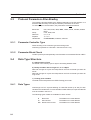
1.3.1 Parameter Maximum Waiting Time for Response . . . . . . . . . . . . . . . . . . . . . . . . . . . . . . . . . . . . .
1.3.2 Parameter Delay Until Connection Setup . . . . . . . . . . . . . . . . . . . . . . . . . . . . . . . . . . . . . . . . . . . . .
1.3.3 Parameter Fast Data Block Access . . . . . . . . . . . . . . . . . . . . . . . . . . . . . . . . . . . . . . . . . . . . . . . . . . .
Data Type Structure. . . . . . . . . . . . . . . . . . . . . . . . . . . . . . . . . . . . . . . . . . . . . . . . . . . . . . . . . . . . . . . . . . . . . . . . .
1.4.1 Data Types . . . . . . . . . . . . . . . . . . . . . . . . . . . . . . . . . . . . . . . . . . . . . . . . . . . . . . . . . . . . . . . . . . . . . . . . . .
1.4.2 Special Simatic Data Formats . . . . . . . . . . . . . . . . . . . . . . . . . . . . . . . . . . . . . . . . . . . . . . . . . . . . . . . .
Additional Functions . . . . . . . . . . . . . . . . . . . . . . . . . . . . . . . . . . . . . . . . . . . . . . . . . . . . . . . . . . . . . . . . . . . . . . . .
Error Messages . . . . . . . . . . . . . . . . . . . . . . . . . . . . . . . . . . . . . . . . . . . . . . . . . . . . . . . . . . . . . . . . . . . . . . . . . . . . .
Guidance for the Employment of CPUs with 2 PU Interfaces . . . . . . . . . . . . . . . . . . . . . . . . . . . . . . . . .
3
4
4
5
5
5
5
7
7
8
9
10
1
Section 1-1
General Information
1.1
General Information
The operating terminals can be conveniently connected to the Siemens PLCs S90 S155 thus making the operating terminals the perfect man-machine-interface for
your Siemens PLC.
The operating terminal is connected to the PU (programming unit) interface of the
PLC. An additional communications module is not necessary. The data communication on the interface is handled by the PU protocol AS511.
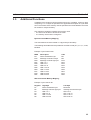
Connections to the following Simatic S5 PLC types are supported:
SIMATIC S5-90U (8-bit CPU)
SIMATIC S5-95U (8-bit CPU)
SIMATIC S5-100U
CPU 100 (8-bit CPU)
CPU 102 (8-bit CPU)
CPU 103 (8-bit CPU)
SIMATIC S5-115U
CPU 941 (8-bit CPU)
CPU 942 (8-bit CPU)
CPU 943 (8-bit CPU)
CPU 944 (8-bit CPU)
CPU 945 (8-bit CPU with 20-bit address range)
SIMATIC S5-135U
CPU 922 (16-bit CPU)
CPU 928 (16-bit CPU)
CPU 928B (16-bit CPU)
SIMATIC S5-155U
CPU 948 (20-bit CPU)
Connection to the following Simatic S5 PLC type is not supported:
SIMATIC S5-135U
CPU 921 (16-bit CPU)
The software components of the system are fully adapted to the parameters and
marginal conditions of the PU interface.
This offers the user the following advantages:
- Random read and write access to all data within the PLC. Data from existing
PLC programs can be displayed and modified directly on the operating terminal.
Since the communication data do not need to be stored in a specified address
area or data type area, it is not necessary to adapt the PLC program to the
operating terminal in any respect.
- The operating terminal automatically polls the freely definable data areas for
cyclic data.
- Use of a PU multiplexer allows simultaneous connection of the operating terminal and Siemens programming unit (PU).
3
Section 1-2
Technical Description
- No configuration required within the PLC.
- The PU protocol is handled entirely by the firmware of the PLC. A PLC program
(function blocks, etc.) in the PLC is not required to handle the communication.
- The protocol provides error control. Transmission errors are detected and, if possible, eliminated by repeating the transmission. An electrically isolated, noiseimmune interface hardware in accordance with the 20 mA current loop interface
standard permits the application even in a harsh industrial environment.
- The parameters of the interface SER1 are assigned in the programming software in a protocol-specific manner and are stored in the application description.
The parameters can also be modified in the setup mask or any other I/O mask of
the terminal.
- The programming system provides a maximum of support to the operator in
programming the operating terminal. The definitions (abbreviations) used here
are identical with the definitions used within the PLC program.
1.2
Technical Description
The PU protocol is used to connect the operating terminal to the Siemens PLCs.
The PU protocol AS511 allows random read and write access to all PLC data. Any
byte-structured data types can also be accessed in bit-mode. The size of the address area depends on the respective PLC.
Access to the individual bytes of a data word within a data block is also possible.
A read access must be performed before individual bits or bytes of a data word
within a data block can be accessed for a write operation. Subsequently, a write
access is possible to the entire data structure. When accessing individual bits or
bytes, special care needs to be taken to ensure that neither the terminal nor the
PLC modify individual bits within one byte (or individual bits within one data word,
respectively).
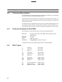
1.3
Protocol Parameters Siemens PU AS511
To ensure proper communication, the parameters must not be altered.
Baud rate:
Parity:
Data length:
Stop bits:
Handshake:
300, 600, 1200, 2400, 4800, 9600, 19200, 38400, 375000,
500000 Baud
none, even, odd
5, 6, 7, 8
1, 1.5, 2
no handshake, Hardware, Software
The operating terminal adapts to the default parameters of the PU interface. It is
therefore not necessary to modify the interface parameters in the PLC. This allows
communication between the operating terminal and Siemens PLC without requiring any configuration.
4
Section 1-4
Data Type Structure
1.3.1
Parameter Maximum Waiting Time for Response
This timer indicates the length of time that the operating terminal (master) waits for
the response from the PLC (slave).
Permitted values are in the range of 0 ms to 65535 ms.
The default value is 500 ms.
This value must be increased when using a CPU with two PU interfaces (see „Guidance for the employment of CPUs with 2 PU interfaces”).
1.3.2
Parameter Delay Until Connection Setup
Specifies the period of time that the terminal allows to elapse after an unsuccessful
attempt to establish the connection and before making another attempt.
Permitted values are in the range of 5000 ms to 255000 ms.
The default value is 10000 ms.
1.3.3
Parameter Fast Data Block Access
The base address for each data block being used is determined only once and this
information is stored temporarily in a local buffer with 10 positions. Any subsequent
accesses continue to operate with the information stored in the local buffer. The
information in the buffer is erased upon restarting the terminal or upon a resynchronization after a communication error.
Important:
In this case, do not modify the size of data blocks or compress the PLC memory
while the connection between the terminal and the PLC is still being established!
If a terminal and a programming unit are simultaneously connected to the PLC by
means of a multiplexer, then any value of the data block that is altered via the
programming unit and transferred into the PLC, also results in a change of the
address location of the data block. In this case, the cache should be deactivated.
1.4
Data Type Structure
a) Alphanumerical Texts
Are stored in the memory byte for byte in ascending address order.
b) Counter
A distinction is made between variables which have been assigned a counter address and variables which have been assigned another PLC address.
Counter address
When accessing counter addresses, the count value is interpreted in the binary
format and the control bits of the counter are masked out. Therefore, to avoid control bits from being erased, counter addresses should be accessed in the readmode only.
5
Section 1-4
Data Type Structure
All other addresses
The count value is interpreted in BCD-code. This allows transfer of this value within
the PLC program to the counter by means of the accumulator. This service should
be used for indirect write-operations of count values since the values are available
in the Siemens conforming format.
c) Timer
Timer functions consist of a time value and a time base. The terminal operates with
imaginary unsigned 4-byte variables even though the data stored in the PLC comprise only 2 bytes.
When read-accessing timers, the terminal converts the time value and time base
into a terminal-internal unsigned 4-byte variable which represents the time value in
reference to the time base of 0.01 second.
Example : A range of 10 (time base is 1.0 second) and a time value of 999 are
represented or edited in the terminal by the value 99900. Scaling of this value to
other value ranges is possible by specifying a factor and divisor within the variable
definition.
Before writing a timer variable to the PLC, a terminal-internal unsigned 4-byte value
is converted to a time value and the smallest possible time base.
In addition, a distinction is made between variables which have been assigned a
timer address or another PLC address.
Timer address
When accessing timer addresses, the time value is interpreted in binary format. To
avoid timer control bits from being erased, this service should be used in the readmode only.
All other addresses
The time value is interpreted BCD-coded. Because the values are available in the
Siemens conforming format, this service should be used for indirect write-operations of time values.
d) Floating Point Number
The data are interpreted in the Siemens floating point format.
e) Binary Variables with a Length of 1, 2 or 4 Bytes
Data with a length of 2 bytes are interpreted in the PLC-conforming byte order for
words.
Data with a length of 4 bytes are interpreted in the PLC-conforming byte order for
long words.
6
Section 1-4
Data Type Structure
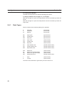
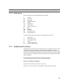
1.4.1
Data Types
Direct accessing of the following data types is possible:
E
A
M
input bits
output bits
flag bits
(bit access, read-only)
(bit access)
(bit access)
EB
AB
MB
input bytes
output bytes
flag bytes
(byte access, read-only)
(byte access)
(byte access)
EW input word
AW output word
MW flag word
(word access, read-only)
(word access)
(word access)
ED
AD
MD
input double word
output double word
flag double word
(double word access, read-only)
(double word access)
(double word access)
DW
DL
DR
DD
data word
data word, left (high)
data word, right (low)
data double word
(word access)
(word access)
(word access)
(double word access)
T
Z
timer
counter
(word access, read-only)
(word access, read-only)
The size of each data area depends on the CPU of the PLC.
1.4.2
Special Simatic Data Formats
The following data formats are supported in the editors:
KB 0 to 255
Variable in byte format
KF -32768 to +32767
Variable in 16-bit fixed point number format
KH 0000 to FFFF
Variable in 4-digit hexadecimal number format
DH 00000000 to FFFFFFFF
Variable in 8-digit hexadecimal number format
KC !! to zz (2 ASCII-characters each)
Variable represented by 2 characters in ASCII format
KT 000.0 to 999.3
Variable represented as a time value
KZ 000 to 999
Variable represented as a count value
KG ±1.2*10-38 to .±3.4*10+38
Variable in 32-bit floating point number format
KM 00000000 00000000 to 11111111 11111111
Variable in bit pattern format
7
Section 1-5
Additional Functions
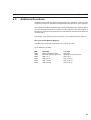
1.5
Additional Functions
In addition to the random read and write access to PLC variables, a 11-byte memory area is specified in the application description as a poll area. The location of this
memory area can also be specified in the application description.
The only marginal conditions regarding this memory area is that the PLC must be
able to access in bit-mode and the terminal in byte-mode and the memory area
must be contiguous.
Access modes of the PLC to the poll area are:
Byte-structured Memory Mapping
The maximum size for the data area is 11 bytes.
Example:
The cyclic poll area is set to flag byte (MB) 12 in the programming system.
Access to the PLC occurs via:
Byte address
Byte address +0
Byte address +1
Byte address +2
Byte address +3
Byte address +4
Byte address +5
Byte address +6
Byte address +7
Byte address +8
Byte address +9
Byte address +10
MB
MB12
MB13
MB14
MB15
MB16
MB17
MB18
MB19
MB20
MB21
MB22
Description
Write coordination byte
Message channel low-byte
Message channel high-byte
Function key LED 1 to 4
Function key LED 5 to 8
Function key LED 9 to 12
Function key LED 13 to 16
Function key LED 17 to 20
Function key LED 21 to 24
Function key LED 25 to 28
Function key LED 29 to 32
Word-structured Memory Mapping
The maximum size for the data area is 6 words or 12 bytes.
Example:
The cyclic data area is set to DW21 in the programming system.
8
Word address
Word address +0
Word address +1
DW
DW21
DW22
High-byte
Write coordination byte
Message channel high-byte
Word address +2
Word address +3
Word address +4
Word address +5
DW23
DW24
DW25
DW26
Function key LED 1 to 4
Function key LED 9 to 12
Function key LED 17 to 20
Function key LED 25 to 28
Low-byte
Reserved
Message channel
low-byte
LED 5 to 8
LED 13 to 16
LED 21 to 24
LED 29 to 32
Section 1-6
Error Messages
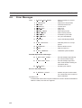
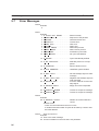
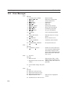
1.6
Error Messages
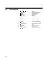
Code
1
2
3
4
E
E
E
E
SLAVE NOT READY . . . . . . . . . .Slave not ready
PROTOKOL . . . . . . . . . . . . . . . . . . . .Sequence of the packets
FRAME . . . . . . . . . . . . . . . . . . . . . . . . .Protocol frame error
TIMEOUT. . . . . . . . . . . . . . . . . . . . . . .Timeout error
6
7
8
9
10
E
E
E
E
E
PARITY. . . . . . . . . . . . . . . . . . . . . . . . .Parity error
SEND ABORT . . . . . . . . . . . . . . . . .Send process aborted
REC ABORT . . . . . . . . . . . . . . . . . . .Receive process aborted
BUF SIZE . . . . . . . . . . . . . . . . . . . . . .Insufficient cyclic buffer
NO DEFINE . . . . . . . . . . . . . . . . . . . .No cyclic data defined
12 E DEFINE . . . . . . . . . . . . . . . . . . . . . . . .Cyclic data already defined
15 E NO PROTOCOL . . . . . . . . . . . . . . .Selected protocol is not supported
16 E OVERRUN. . . . . . . . . . . . . . . . . . . . . .Receive buffer overrun
17 E NAK . . . . . . . . . . . . . . . . . . . . . . . . . . . .NAK from PLC despite repetition
40 E SYS ADDRESS . . . . . . . . . . . . . . . .Undefined system variable
Siemens-specific error messages
50 E BST RANGE . . . . . . . . . . . . . . . . . . .Address outside of the range of
the data block
51 E RECEIVE COUNT. . . . . . . . . . . . . .Number of data received is incorrect
52 E FUN NOT KNOWN . . . . . . . . . . . .Unknown function
53 E WRONG MODE . . . . . . . . . . . . . . . .Wrong mode of operation
54 E DATA BLOCK NOT KNOWN. .Data block does not exist
55 E HIGH LEVEL . . . . . . . . . . . . . . . . . . .Communication has reached
higher level
56 E LOW LEVEL . . . . . . . . . . . . . . . . . . .Communication has reached
lower level
57 E MESSAGE CONNECT . . . . . . . . .Invalid feedback received from
the PLC during the connection
setup phase
58 E MESSAGE TRANSFER . . . . . . . .Invalid feedback received from
the PLC during the transfer
phase
59 E MESSAGE DISCONNECT. . . . . .Invalid feedback received from
the PLC during the disconnect
phase
60 E CPU TYP 921 . . . . . . . . . . . . . . . . .A CPU of the type 921 has been
detected. The operating terminal does not support this CPU
type.
61 E WRONG ADDR . . . . . . . . . . . . . . . .Wrong addressing used for job.
The requested address level is
not fully available.
9
Guidance for the Employment of CPUs with 2 PU Interfaces
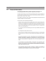
1.7
Section 1-7
Guidance for the Employment of CPUs with 2 PU
Interfaces
CPUs with 2 PU interfaces (e.g. 928B with PU module) are used during system
commissioning thus keeping the PU interface available for program debugging.
Please note that the interfaces are interacting (see Siemens CPU manual). For
example, if a PLC program is analysed by means of the STATUS-function on the
first interface of the CPU, this will cause the speed of protocol handling on the
second interface to decrease significantly. With the STATUS-function, the PLC
program can, so to speak, be operated in the single-step-mode, i.e. the result of
every program line is displayed on the screen.
In order to maintain the connection, the timeout period must be increased to 5
seconds. Using the regular timeout period results in the terminal generating a communication error message.
In this case, each transmission requires 3-4 seconds, in contrast to a regular communication cycle which requires approximately 60 ms. This means a slow-down of
the interface by a factor of 50!
10
SECTION 2
GE Fanuc SNP
2.1
2.2
2.3
2.4
2.5
2.6
General Information . . . . . . . . . . . . . . . . . . . . . . . . . . . . . . . . . . . . . . . . . . . . . . . . . . . . . . . . . . . . . . . . . . . . . . . .
Protocol Parameters GE Fanuc SNP . . . . . . . . . . . . . . . . . . . . . . . . . . . . . . . . . . . . . . . . . . . . . . . . . . . . . . . . .
2.2.1 Parameter Maximum Waiting Time for Response . . . . . . . . . . . . . . . . . . . . . . . . . . . . . . . . . . . . .
2.2.2 Parameter Delay Until Connection Setup . . . . . . . . . . . . . . . . . . . . . . . . . . . . . . . . . . . . . . . . . . . . .
Configuring the PLC . . . . . . . . . . . . . . . . . . . . . . . . . . . . . . . . . . . . . . . . . . . . . . . . . . . . . . . . . . . . . . . . . . . . . . . .
2.3.1 CPU - ID. . . . . . . . . . . . . . . . . . . . . . . . . . . . . . . . . . . . . . . . . . . . . . . . . . . . . . . . . . . . . . . . . . . . . . . . . . . .
Data Types . . . . . . . . . . . . . . . . . . . . . . . . . . . . . . . . . . . . . . . . . . . . . . . . . . . . . . . . . . . . . . . . . . . . . . . . . . . . . . . . .
Additional Functions . . . . . . . . . . . . . . . . . . . . . . . . . . . . . . . . . . . . . . . . . . . . . . . . . . . . . . . . . . . . . . . . . . . . . . . .
Error Messages . . . . . . . . . . . . . . . . . . . . . . . . . . . . . . . . . . . . . . . . . . . . . . . . . . . . . . . . . . . . . . . . . . . . . . . . . . . . .
13
14
14
14
14
14
15
15
16
11
Section 2-1
General Information
2.1
General Information
The operating terminals allow for a simple connection to every GE FANUC PLC of
the 90 series thus making the operating terminals the perfect man-machine-interface for your FANUC PLC.
The operating terminal is connected to the Programming and Communications
Port of the PLC-CPU. An additional communications module is not necessary. The
data communication on the interface is handled by the FANUC-Series 90 protocol
(SNP-protocol).
The software components of the system are fully adapted to the parameters and
marginal conditions of the SNP interface.
This offers the user the following advantages:
- Random write and read access to any data within the PLC. Data of existing PLC
programs can be displayed and modified directly in the operating terminal. It is
not necessary to adapt the PLC program to the operating terminal in any respect
since it is not required that communications data be stored in a specified address area or data type area.
- The operating terminal automatically polls the freely definable data areas for
cyclic data.
- Configuration of a bus topology is possible. Use of a SNP multiplexer allows
simultaneous connection of the operating terminal and the hand-held programming unit (HHP) or the Logicmaster (PC with LM90 software), respectively.
- Only a minimum of configuration is required in the PLC. Point-to-point connections require no configuration at all in the PLC. A bus topology will require setting
of only one parameter for the communication, namely the slave identifier (CPUID) for the PLC. This slave identifier is entered once with the LM90.
- The SNP protocol is handled entirely by the operating system of the PLC. A PLC
program in the PLC is not required for the handling of the communication.
- The protocol provides error control. Transmission errors are detected and, if
possible, eliminated by repeating the transmission. A noise-immune interface
hardware in accordance with the RS485 interface standard permits the application even in a harsh industrial environment.
- The parameters of the interface SER1 are assigned in the programming software in a protocol-specific manner and are stored in the application description.
Modifying of the parameters is possible in the setup mask or in each other I/Omask of the terminal at any time.
- The programming system provides a maximum of support to the operator in
programming the operating terminal. The definitions (abbreviations) used here
are identical with the definitions used within the PLC program (e.g. %M3 corresponds to flag 3).
13
Section 2-2
Protocol Parameters GE Fanuc SNP
2.2
Protocol Parameters GE Fanuc SNP
The parameters of the interface SER1 are set to the following values:
Baud rate:
Parity:
Data length:
Stopbits:
Handshake:
300, 600, 1200, 2400, 4800, 9600, 19200, 38400, 357000,
500000 Baud
none, even, odd
5, 6, 7, 8 bits
1, 1.5, 2
No handshake, Hardware, Software
The default parameters of the programming software are printed bold.
The operating terminal adapts to the default parameters of the SNP protocol.
Therefore it is generally not necessary to alter the interface parameters in the PLC.
2.2.1
Parameter Maximum Waiting Time for Response
This timer indicates the length of time that the operating terminal (master) will wait
for the response from the PLC (slave).
Permitted values are in the range of 50 ms to 65535 ms.
The default value is 1000 ms.
2.2.2
Parameter Delay Until Connection Setup
Specifies the period of time that the terminal allows to elapse after an unsuccessful
attempt to establish the communication and before making another attempt.
Permitted values are in the range of 5000 ms to 255000 ms.
The default value is 10000 ms.
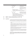
2.3
Configuring the PLC
Before any communication between the operating terminal and FANUC-PLC is
possible, it will be necessary to set the CPU ID parameter with the aid of a LM90.
2.3.1
CPU - ID
The operating terminal considers the PLC a slave and, thus, references it via a
slave number. This slave number is assigned to the variable during the creation of
the application definition. Valid slave numbers range from value 1 to value 253.
Having defined a slave number 1 to 253 in the application definition will require that
the same CPU-ID consisting of 3 characters must be specified in the PLC. Any
blank digits will be filled in with zeros (slave number 23 corresponds to the CPUidentifier 023).
It is also possible to work without a CPU-identifier by specifying the slave identifier
254 in the application definition. In this event it must be ensured that the connection
between terminal and PLC is a point-to-point-connection.
14
Section 2-5
Additional Functions
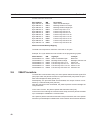
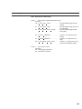
2.4
Data Types
User references are bit, byte, or word-structured.
Reference type
Discrete Inputs
Discrete Outputs
Temporary Coils
Internal Coils
System Status References
Discrete Globals
Analog Inputs
Analog Outputs
Registers
Sign
%I
%Q
%T
%M
%SA, %SB, %SC, %S
%G
%AI
%AQ
%R
Orientation
Bit / Byte
Bit / Byte
Bit / Byte
Bit / Byte
Bit / Byte
Bit / Byte
Word / Double word
Word / Double word
Word / Double word
The size of each reference area is governed by the size of the PLC’s CPU.
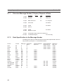
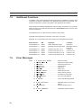
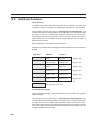
2.5
Additional Functions
In addition to the random write and read access to PLC variables, a memory area
comprising 11 or 12 bytes is specified in the application definition as poll area. The
location of this memory area is specified in the application definition.
Only marginal conditions regarding this memory area:
- the PLC must be able to access in bit-mode and the SNP in byte-mode
- the memory area must be contiguous.
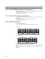
Byte-structured Memory Mapping
The data area comprises a maximum of 11 bytes
The start address must be located on a physical byte boundary.
The following start addresses are possible in accordance with (8 * n) + 1 ; n =
0, 1 , 2 : M1, M9, M17.
Example: Cyclic Data starts at %M1
MSB
%M8
%M16
%M24
%M32
%M40
%M48
%M56
%M64
%M72
%M80
%M88
Description
Write Coordination Byte
Message Channel Low byte
Message Channel High byte
LED 1 to 4
LED 5 to 8
LED 8 to 12
LED 13 to 16
LED 17 to 20
LED 21 to 24
LED 25 to 28
LED 29 to 32
LSB
%M1
%M9
%M17
%M25
%M33
%M41
%M49
%M57
%M65
%M73
%M81
Word-structured Memory Mapping
The data area comprises a maximum of 6 words or 12 bytes.
15
Section 2-6
Error Messages
Example: The cyclic data on %R1
Register
%R1
%R2
%R3
%R4
%R5
%R6
2.6
High byte
Write Coordination Byte
Message Channel High byte
LED 1 to 4
LED 9 to 12
LED 17 to 20
LED 25 to 28
Low byte
Reserved
Message Channel Low byte
LED 5 to 8
LED 13 to 16
LED 21 to 24
LED 29 to 32
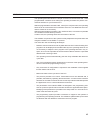
Error Messages
Code
1 E SLAVE NOT READY . . . . . . . . . .Slave not ready or incorrect
CPU-ID
2 E PROTOKOL . . . . . . . . . . . . . . . . . . . .Sequence of the packets
3 E FRAME . . . . . . . . . . . . . . . . . . . . . . . . .Character frame error
4 E TIMEOUT. . . . . . . . . . . . . . . . . . . . . . .Timeout error
5 E CRC BCC. . . . . . . . . . . . . . . . . . . . . .CRC error
6 E PARITY. . . . . . . . . . . . . . . . . . . . . . . . .Parity error
7 E SEND ABORT . . . . . . . . . . . . . . . . .Abort send process
8 E REC ABORT . . . . . . . . . . . . . . . . . . .Abort receive process
9 E BUF SIZE . . . . . . . . . . . . . . . . . . . . . .Insufficient cyclic buffer
10 E NO DEFINE . . . . . . . . . . . . . . . . . . . .No cyclic data defined
12 E DEFINE . . . . . . . . . . . . . . . . . . . . . . . .Cyclic data already defined
14 E SLAVE ADDRESS . . . . . . . . . . . . .Invalid slave address (e.g. 0x00
master-address)
15 E NO PROTOCOL . . . . . . . . . . . . . . .Selected protocol is not supported
16 E OVERRUN. . . . . . . . . . . . . . . . . . . . . .Receive buffer overrun
18 E NAK 0 . . . . . . . . . . . . . . . . . . . . . . . . .BCC or parity error from PLC
19 E NAK 0 . . . . . . . . . . . . . . . . . . . . . . . . .Overrun or framing error from
PLC
20 E NAK 0
Sequence error from PLC
21 E NAK 0 . . . . . . . . . . . . . . . . . . . . . . . . .Bad Next Message Length error
from PLC
40 E SYS ADDRESS . . . . . . . . . . . . . . . .Undefined system variable or
invalid slave number 255
Fanuc-specific error messages
Code 50 - 138
178 - 25
16
Major error status code. . . . . . .The error number consists of
the constant 50 and the error
status
Minor error status code of the SNP-partner-module
SECTION 3
Mitsubishi FX
3.1
3.2
3.3
3.4
3.5
3.6
General Information . . . . . . . . . . . . . . . . . . . . . . . . . . . . . . . . . . . . . . . . . . . . . . . . . . . . . . . . . . . . . . . . . . . . . . . .
Technical Description . . . . . . . . . . . . . . . . . . . . . . . . . . . . . . . . . . . . . . . . . . . . . . . . . . . . . . . . . . . . . . . . . . . . . . .
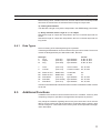
Protocol parameters Mitsubishi FX . . . . . . . . . . . . . . . . . . . . . . . . . . . . . . . . . . . . . . . . . . . . . . . . . . . . . . . . . .
3.3.1 Parameter Maximum Waiting Time for Response . . . . . . . . . . . . . . . . . . . . . . . . . . . . . . . . . . . . .
3.3.2 Parameter Delay Until Connection Setup . . . . . . . . . . . . . . . . . . . . . . . . . . . . . . . . . . . . . . . . . . . . .
Data Types . . . . . . . . . . . . . . . . . . . . . . . . . . . . . . . . . . . . . . . . . . . . . . . . . . . . . . . . . . . . . . . . . . . . . . . . . . . . . . . . .
Additional Functions . . . . . . . . . . . . . . . . . . . . . . . . . . . . . . . . . . . . . . . . . . . . . . . . . . . . . . . . . . . . . . . . . . . . . . . .
Error Messages . . . . . . . . . . . . . . . . . . . . . . . . . . . . . . . . . . . . . . . . . . . . . . . . . . . . . . . . . . . . . . . . . . . . . . . . . . . . .
19
20
20
20
20
20
21
22
17
Section 3-1
General Information
3.1
General Information
The operating terminals allow for a simple connection to every Mitsubishi PLC of
the FX series thus making the operating terminals the perfect man-machine-interface for your Mitsubishi PLC.
The operating terminal is connected to the programming unit interface of the
PLC. An additional communications module is not necessary. The data communication on the interface is handled by the Mitsubishi FX protocol.
The software components of the system are fully adapted to the parameters and
marginal conditions of the interface.
This offers the user the following advantages:
- Random write and read access to any data within the PLC. Data of existing PLC
programs can be displayed and modified directly in the operating terminal. It is
not necessary to adapt the PLC program to the operating terminal in any respect
since it is not required that communications data be stored in a specified address area or data type area.
- The operating terminal automatically polls the freely definable data areas for
cyclic data.
- No configuration is required in the PLC.
- The protocol is handled entirely by the operating system of the PLC. A PLC
program in the PLC is not required for the handling of the communication.
- The protocol provides error control. Transmission errors are detected and, if
possible, eliminated by repeating the transmission. A noise-immune interface
hardware in accordance with the RS485 interface standard permits the application even in a harsh industrial environment.
- The parameters of the interface SER1 are assigned in the programming software in a protocol specific manner and are stored in the application description.
Modifying of the parameters is possible in the setup mask or in each other I/Omask of the terminal at any time.
- The programming system provides a maximum of support to the operator in
programming the operating terminal. The definitions (abbreviations) used here
are identical with the definitions used within the PLC program (e.g. M3 corresponds to flag 3).
19
Section 3-2
Technical Description
3.2
Technical Description
The interfacing of the operating terminal to the Mitsubishi-FX Series- PLCs is effected by means of the FX protocol.
The FX protocol allows random read and write access to all PLC (programmable
logic controller) data. Any byte-structured data types can also be accessed in bitmode. The size of the address area depends on the respective PLC.
3.3
Protocol parameters Mitsubishi FX
The parameters of the interface SER1 are set to the following values:
Baud rate:
Parity:
Data length:
Stopbits:
Handshake:
300, 600, 1200, 2400, 4800, 9600, 19200, 38400, 375000,
500000 Baud
none, even, odd
5, 6, 7, 8 bits
1, 1.5, 2
No Handshake, Hardware, Software
The default parameters of the programming software are printed in bold.
3.3.1
Parameter Maximum Waiting Time for Response
This timer indicates the length of time that the operating terminal (master) will wait
for the response from the PLC (slave).
Permitted values are in the range of 0 ms to 65535 ms.
The default value is 5000 ms.
3.3.2
Parameter Delay Until Connection Setup
Specifies the period of time that the terminal allows to elapse after an unsuccessful
attempt to establish the communication and before making another attempt.
Permitted values are in the range of 5000 ms to 255000 ms.
The default value is 10000 ms.
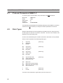
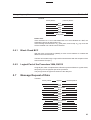
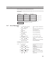
3.4
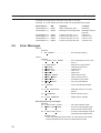
Data Types
Type
S
X
Y
M
T
T
C
C
M
D
20
Description
Step flag operand (status)
Inputs
Outputs
Flags
Timer flags
Time Value
Count Flags
Count Values
Flag
(also Special Flag)
Data Register
(also Special Data Register)
Access
access in bit and byte mode
access in bit and byte mode
access in bit and byte mode
access in bit and byte mode
access in bit and byte mode
access in word mode
access in bit and byte mode
access in word (double word) mode
access in bit and byte mode
access in word (double word) mode
Section 3-5
Additional Functions
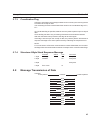
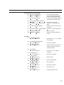
3.5
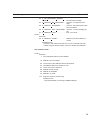
Additional Functions
In addition to the random write and read access to PLC variables, a memory area
comprising 11 or 12 bytes is specified in the application description as cyclic data
area. The location of this memory area is specified in the mask definition and must
be located on a byte boundary.
Only marginal conditions regarding this memory area:
- the PLC must be able to access in bit-mode
- the memory area must be contiguous.
Byte-structured Memory Mapping
The start address must be located on a physical byte boundary.
The following start addresses are possible in accordance with (8 * n) n = 0, 1, 2 : M0,
M8 M16.
Example: Cyclic Data on M0
MSB
M7
M15
M23
M31
M39
M47
M55
M63
M71
M79
M87
Description
Write coordination byte
Message channel low byte
Message channel high byte
LED 1 to 4
LED 5 to 8
LED 9 to 12
LED 13 to 16
LED 17 to 20
LED 21 to 24
LED 25 to 28
LED 29 to 32
LSB
M0
M8
M16
M24
M32
M40
M48
M56
M64
M72
M80
Word-structured Memory Mapping
Example: Cyclic data on D1
Register
D1
D2
D3
D4
D5
D6
High-byte
Write coordination byte
Message channel high-byte
LED 1 to 4
LED 9 to 12
LED 17 to 20
LED 25 to 28
Low-byte
Reserved
message channel low-byte
LED 5 to 8
LED 13 to 16
LED 21 to 24
LED 29 to 32
21
Section 3-6
Error Messages
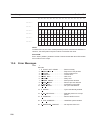
3.6
Error Messages
Code
1 E SLAVE NOT READY . . . . . . . . . .Slave not ready or incorrect
CPU-ID
2 E PROTOKOL . . . . . . . . . . . . . . . . . . . .Sequence of the packets
3 E FRAME . . . . . . . . . . . . . . . . . . . . . . . . .Character frame error
4 E TIMEOUT. . . . . . . . . . . . . . . . . . . . . . .Timeout error
5 E CRC BCC. . . . . . . . . . . . . . . . . . . . . .CRC error
6 E PARITY. . . . . . . . . . . . . . . . . . . . . . . . .Parity error
7 E SEND ABORT . . . . . . . . . . . . . . . . .Abort send process
8 E REC ABORT . . . . . . . . . . . . . . . . . . .Abort receive process
9 E BUF SIZE . . . . . . . . . . . . . . . . . . . . . .Insufficient cyclic buffer
10 E NO DEFINE . . . . . . . . . . . . . . . . . . . .No cyclic data defined
12 E DEFINE . . . . . . . . . . . . . . . . . . . . . . . .Cyclic data already defined
15 E NO PROTOCOL . . . . . . . . . . . . . . .Selected protocol is not supported
16 E OVERRUN. . . . . . . . . . . . . . . . . . . . . .Receive buffer overrun
17 E NAK . . . . . . . . . . . . . . . . . . . . . . . . . . . .NAK from the PLC
40 E SYS ADDRESS . . . . . . . . . . . . . . . .Undefined system variable
22
SECTION 4
SINEC L1
4.1
4.2
4.3
4.4
4.5
4.6
Protocol Parameters SINEC L1 . . . . . . . . . . . . . . . . . . . . . . . . . . . . . . . . . . . . . . . . . . . . . . . . . . . . . . . . . . . . . .
Data Types . . . . . . . . . . . . . . . . . . . . . . . . . . . . . . . . . . . . . . . . . . . . . . . . . . . . . . . . . . . . . . . . . . . . . . . . . . . . . . . . .
4.2.1 Data Type Structure . . . . . . . . . . . . . . . . . . . . . . . . . . . . . . . . . . . . . . . . . . . . . . . . . . . . . . . . . . . . . . . . .
Configuring the PLC . . . . . . . . . . . . . . . . . . . . . . . . . . . . . . . . . . . . . . . . . . . . . . . . . . . . . . . . . . . . . . . . . . . . . . . .
4.3.1 Status Data Area . . . . . . . . . . . . . . . . . . . . . . . . . . . . . . . . . . . . . . . . . . . . . . . . . . . . . . . . . . . . . . . . . . . .
Error Messages . . . . . . . . . . . . . . . . . . . . . . . . . . . . . . . . . . . . . . . . . . . . . . . . . . . . . . . . . . . . . . . . . . . . . . . . . . . . .
SINEC L1-Data Handling Software for S5 115U . . . . . . . . . . . . . . . . . . . . . . . . . . . . . . . . . . . . . . . . . . . . . .
4.5.1 Installation . . . . . . . . . . . . . . . . . . . . . . . . . . . . . . . . . . . . . . . . . . . . . . . . . . . . . . . . . . . . . . . . . . . . . . . . . .
4.5.2 Interface to the Application Software . . . . . . . . . . . . . . . . . . . . . . . . . . . . . . . . . . . . . . . . . . . . . . . . .
4.5.3 Initialization Function Block FB200 . . . . . . . . . . . . . . . . . . . . . . . . . . . . . . . . . . . . . . . . . . . . . . . . . .
4.5.4 Communications Function Block FB201 . . . . . . . . . . . . . . . . . . . . . . . . . . . . . . . . . . . . . . . . . . . . . .
SINEC L1 Data Handling Software for S5 135U with CP530 . . . . . . . . . . . . . . . . . . . . . . . . . . . . . . . . . .
4.6.1 Installation . . . . . . . . . . . . . . . . . . . . . . . . . . . . . . . . . . . . . . . . . . . . . . . . . . . . . . . . . . . . . . . . . . . . . . . . . .
4.6.2 Interface to the Application Software . . . . . . . . . . . . . . . . . . . . . . . . . . . . . . . . . . . . . . . . . . . . . . . . .
4.6.3 Initialization Function Block FB200 . . . . . . . . . . . . . . . . . . . . . . . . . . . . . . . . . . . . . . . . . . . . . . . . . .
4.6.4 Communications Function Block FB201 . . . . . . . . . . . . . . . . . . . . . . . . . . . . . . . . . . . . . . . . . . . . . .
4.6.5 Parameterizing the CP530 . . . . . . . . . . . . . . . . . . . . . . . . . . . . . . . . . . . . . . . . . . . . . . . . . . . . . . . . . . . .
26
26
27
28
28
28
30
30
31
31
32
32
32
33
33
34
34
23
Section 4
SINEC L1
The operating terminals allow for a simple connection to the Siemens S95 - S155
programmable controllers thus making the operating terminals the perfect manmachine-interface for your Siemens PLC.
With the programmable controllers 95U, 100U (CPU 103) and 155U, the operating
terminal can be connected to the PU interface of the PLC. An additional communications module is not necessary.
With the programmable controllers 115U, 135U and 155U, a connection is possible
via a CP530 communications processor.
In either case, the operating terminal is the master of the bus.
The software components of the system are fully adapted to the parameters and
marginal conditions of the SINEC L1 protocol.
This offers the user the following advantages:
- Random write and read access to any data within the PLC. Data of existing PLC
programs can be displayed and modified directly in the operating terminal. It is
not necessary to adapt the PLC program to the operating terminal in any respect, since it is not required that communications data be stored in a specified
address area or data type area.
- The operating terminal automatically polls the freely definable data areas for
cyclic data.
- Use of a PU multiplexer allows simultaneous connection of the operating terminal and a hand-held programming unit (PU).
- Only a minimum of configuration is required for the installation of the supplied
function blocks into the PLC.
- Minimal increase of the cycle time of the PLC.
- The protocol provides error control. Transmission errors are detected and, if
possible, eliminated by repeating the transmission. A noise-immune interface
hardware in accordance with the 20 mA current loop interface standard permits
the application even in a harsh industrial environment.
- The parameters of the interface SER1 are assigned in the programming software in a protocol-specific manner and are stored in the application description.
Modifying of the parameters is possible in the setup mask or in each other I/Omask of the terminal at any time.
- The programming system provides a maximum of support to the operator in
programming the operating terminal. The definitions (abbreviations) used here
are identical with the definitions used within the PLC program.
25
Section 4-1
Protocol Parameters SINEC L1
4.1
Protocol Parameters SINEC L1
To ensure proper communication, the parameters must not be altered.
Baud rate:
Parity:
Data length:
Stopbits:
Handshake:
9600 Baud
even
8
1
no handshake
The operating terminal adapts to the default parameters of the SINEC L1 interface.
Therefore it is not necessary to modify the interface parameters in the PLC.
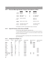
4.2
Data Types
Random read and write access is possible to any data in the PLC. All byte-structured data types can also be accessed in bit-mode. The size of the address area
depends on the PLC being used.
Access to the individual bytes of a data word within a data block is also possible.
Direct access is possible to the following data types:
E
A
M
input bits
output bits
flag bits
(read-only)
EB
AB
MB
input bytes
output bytes
flag bytes
(read-only)
EW
AW
MW
input word
output word
flag word
(read-only)
ED
AD
MD
input double word
output double word
flag double word
(read-only)
DW
DL
DR
DD
data word
data word, left-hand (high)
data word, right-hand (low)
data double word
T
Z
timer
counter
(read-only)
(read-only)
The size of each data area is governed by the CPU of the PLC.
26
Section 4-2
Data Types
4.2.1
Data Type Structure
a) Alphanumerical Text
Is stored in the memory byte for byte in ascending address order.
b) Counter
A distinction is made between variables which have been assigned a counter address and variables which have been assigned another PLC address.
Counter address
When accessing counter addresses, the count value is interpreted in the binary
format, the control bits of the counter are masked out. Therefore, to avoid control
bits from being erased, counter addresses should be accessed in the read-mode
only.
All other addresses
The count value is interpreted in BCD-code. This allows the transfer of this value
within the PLC program to the counter by means of the accumulator. This function
should be used for indirect write-operations of count values since the values are
available in the Siemens conformal format.
c) Timer
Timer functions consist of a time value and a time base. The terminal operates with
imaginary unsigned 4-byte variables, even though the data stored in the PLC comprise only 2 bytes.
When read-accessing the timer, the terminal converts the time value and time base
into a terminal-internal unsigned 4-byte number, which represents the time value in
reference to the time base of 0.01 seconds.
Example: A range of 10 (time base is 1.0 second) and a time value of 999, are
represented or edited, respectively, in the terminal by the value 99900. Scaling of
this value to other value ranges is possible by specifying a factor and divisor within
the variable definition.
Before writing a timer variable to the PLC, the time value and the smallest possible
time base are formed from the terminal-internal unsigned 4-byte value.
In addition, a distinction is made between variables which have been assigned a
timer address and variables which have been assigned another PLC address.
Timer address
When accessing timer addresses, the time value is interpreted in the binary format.
To avoid timer control bits from being erased, this access should occur in the readmode only.
All other addresses
The time value is interpreted BCD-coded. This access should be used for indirect
write-operations of time values since the values are available in the Siemens conformal format.
27
Section 4-3
Configuring the PLC
d) Floating Point Number
The data are interpreted in the Siemens floating point format.
e) Binary Variables with a Length of 1, 2 or 4 Bytes
Data with a length of 2 bytes are interpreted in the PLC-conformal byte order for
words.
Data with a length of 4 bytes are interpreted in the PLC-conformal byte order for
long words.
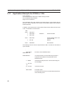
4.3
Configuring the PLC
Before a communication between the operating terminal and the Siemens PLC is
possible, the supplied function blocks must be installed and executed during the
PLC start-up or at cyclic intervals, respectively, and a communications data block
must be specified in the RAM of the PLC.
4.3.1
Status Data Area
In addition to the random read and write access to PLC variables, an area comprising 6 words (DW70 - DW75) is available in the data block which allows the PLC to
influence the terminal (status data area). The transmission of the entire area to the
terminal is activated as soon as the value 128 is written into DL69. After the transmission, DL69 will be reset to 0 by the FB201.
The status data area is word-structured and has been assigned to fixed addresses:
DL70 :
DR70 :
DW71 :
DW72 - DW76 :
4.4
28
Write coordination byte
Reserved
Sequential message channel
LED-bits for function keys
Error Messages
Code 1
E SLAVE NOT READY . . . . . . . . . .The slave address has been
sent, however, no response has
been received within the specified time period of 5 seconds.
Possible causes for the error:
- Incorrect slave address.
- No hardware connection.
2
E FRAME . . . . . . . . . . . . . . . . . . . . . . . . .The SIO has detected a framing
error.
Possible cause for the error:
- Incorrect interface parameter in the terminal or in the PLC.
4 E TIMEOUT. . . . . . . . . . . . . . . . . . . . . . .After successful completion of
the addressing phase and after
sending the telegram from the
terminal to the PLC, the response telegram from the PLC
has not been received within
the bus monitoring time period
of 300 ms.
Error Messages
Section 4-4
5 E CRC BCC. . . . . . . . . . . . . . . . . . . . . .Checking of BCC1 or BCC2 has
revealed a transmission error.
6 E PARITY. . . . . . . . . . . . . . . . . . . . . . . . .Detection of a parity error.
16 E OVERRUN. . . . . . . . . . . . . . . . . . . . . .The interrupt service routine
has not picked up the received
characters quickly enough from
the SIO.
Possible cause for the error:
- Programming error in the terminal.
17 E NAK . . . . . . . . . . . . . . . . . . . . . . . . . . . .Error bit in ZBS has been set.
Possible causes for the error:
- The PLC has detected that an error (e.g. parity error) has occurred
during transmission of the telegram from the Terminal to the PLC.
- PLC is in the stop-mode.
40 E SYS ADDRESS . . . . . . . . . . . . . . . .Undefined system variable or
invalid slave number 255
51 E POLL NR . . . . . . . . . . . . . . . . . . . . . .After transmitting a write or read
request to the function block in
the PLC, no response has been
received within the maximum
number of poll attempts (100).
Possible causes for the error:
- Function block FB201 in the PLC is not being executed.
- PLC is in the stop mode.
- PLC is overloaded and is therefore not capable of assembling the
response quickly enough (unlikely).
52 E RECV ADDR . . . . . . . . . . . . . . . . . . .The address received during
the addressing phase does not
correspond to the transmitted
address.
Possible cause for the error:
- Transmission error not identified
despite of parity check.
53 E QV BIT. . . . . . . . . . . . . . . . . . . . . . . . .The request bit (ZBS) for internode communication is set to
logic 1.
Possible cause for the error:
- The SINEC L1 interface in the PLC is not accessed by the function
block FB201 exclusively (PLC-application program error).
29
Section 4-4
Error Messages
54 E RECV LEN. . . . . . . . . . . . . . . . . . . . .The length of the data received,
exceeded 64 bytes.
55 E DEST. . . . . . . . . . . . . . . . . . . . . . . . . . .The destination in the telegram
from the PLC to the terminal
does not correspond to 0 (master address).
Possible cause for the error:
- The SINEC L1 interface in the PLC is not accessed by the function
block FB201 exclusively (PLC-application program error).
56 E DATA TYPE . . . . . . . . . . . . . . . . . . .An attempt was made to read a
data type which is not supported by the function block FB201.
Possible causes for the error:
- Function block FB201 has been reduced in order to save memory
space and no longer supports all data types.
- Attempt to write-access inputs, timers or counters.
- Mask definition in the FLASH-EPROM contains errors.
4.5
SINEC L1-Data Handling Software for S5 115U
4.5.1
Installation
The interfacing of the operating terminals to the Simatic S5 115U via the PU-interface
by means of the SINEC L1 protocol requires the installation of the supplied data
handling software into the PLC. To install the software, carry out the following steps:
- The four supplied function blocks FB200, FB201, FB202 and FB203 must be
installed.
- A data block (L1DB) must be created in the RAM of the PLC. The minimum size
required for this data block is 77 data words. The data block can either be created with the aid of the programming unit or through the start-up OBs. This
process must be carried out before one of the function blocks mentioned above
is executed for the first time.
- FB200 must be executed through the start-up blocks OB21 and OB22. FB200
will parameterize the system data area for the SINEC L1 communication and
perform the required initialization of data in L1DB.
- FB201 must be executed through OB1. FB201 controls the data exchange with
the operating terminal. When necessary, it will execute FBs 202 or 203 for this
process. These two function blocks may not be executed directly by the application software.
The function blocks use flag words FW252 and FW254 as scratch flags. This
means that if you wish to retain the information in the flags, it will be necessary to
transfer the contents of these flag words before the communications function
blocks are executed.
30
Section 4-5
SINEC L1-Data Handling Software for S5 115U
4.5.2
Interface to the Application Software
The interface to the PLC application software is not of a very complex design. This
is due to the fact that the supplied function blocks handle the entire data exchange
process with the operating terminal via the send mail box and receive mail box. The
function blocks merely need to be executed as described above.
The function blocks also control every access, read-access as well as write-access, to data in the PLC. Again, there is no need for an application software for this
process.
The only task remaining for the application software is the transfer of the status
data area. For this process, an area comprising 6 words (DW70 to DW75) has been
reserved in the communications data block L1DB. This area allows the PLC to
influence the terminal.
The entire area will be transferred to the terminal whenever the value 1 is written
into DL69. After the transmission has been completed, the supplied function blocks
will reset DL69 to 0. Thus DL69 represents a coordination byte which is used to
control the points of time at which the status data area is to be transferred or indicates whether the transfer has already been effected.
The coordination byte can also be used by the application software for the function
communication monitoring. This is possible since the coordination byte is reset to 0
after a specified period of time only if the PLC is still connected to the operating
terminal. The timeout period should logically be greater than 1 second.
All other data of the L1DB, with the exception of the data mentioned above, may not
be accessed by the application software.
4.5.3
Initialization Function Block FB200
The process of executing FB200 through the start-up blocks OB21 and OB22 must
be carried out only once. Prior to this, however, the communications data block
L1DB must have been created since access to certain words of this data block is
required for the execution process.
This function block initializes the system data area of the PLC using SINEC L1
communication parameters.
The following values are entered for the parameters:
PU-number:
Slave-number:
KBE:
KBS:
Receive mail box:
Send mail box:
not relevant here
as specified during programming of the terminal
DW1 in L1DB
DW0 in L1DB
DW36 to DW68 in L1DB
DW2 to DW34 in L1DB
In addition, FB200 performs the required initialization processes in L1DB.
The only parameter to be defined for FB200 is the number of the communications
data block L1DB.
31
SINEC L1-Data Handling Software for S5 115U
4.5.4
Section 4-5
Communications Function Block FB201
FB201 must be executed by OB1 at cyclic intervals. The handling of the data exchange with the operating terminal is performed entirely by this function block. This
process involves that the FB, each time it is being executed, verifies whether a read
or write request has been received from the terminal and carries out such a request, if necessary. To carry out a read or write request, it will execute FB202 or
FB203, respectively, which are responsible for reading or writing to variables, respectively.
In the event that the terminal has not sent a request, the FB will check whether the
status data area is to be transferred to the terminal and will, if necessary, carry out
this process.
The only parameter to be defined for FB201 is the number of the communications
data block L1DB.
4.6
SINEC L1 Data Handling Software for S5 135U with CP530
4.6.1
Installation
The interfacing of the operating terminals to the Simatic S5 135U via the CPU 530
requires the installation of the supplied data handling software into the PLC. To
install the software, carry out the following steps:
- The four supplied function blocks FB200, FB201, FB202 and FB203 must be
installed.
- A data block (L1DB) must be created in the RAM of the PLC. The minimum size
required for this data block is 93 data words. The data block can either be created with the aid of the programming unit or through the start-up OBs. This
process must be carried out before one of the function blocks mentioned above
is executed for the first time. The block must be assigned the number 15, since
this is the number that is being used for the parameterization of the SEND and
RECEIVE data handling block FB201. In the event that DB-number 15 has already been used elsewhere, another option is to alter the DBNR parameter
when executing the data handling blocks in FB 201.
- FB200 must be executed through start-up blocks OB20, OB21 and OB22. FB
200 will handle the synchronization with the CP530 and also carry out the required initialization of the data in L1DB.
- FB201 must be executed through OB1. FB 201 controls the data exchange with
the operating terminal. When necessary, it will execute FBs 202 or 203 for this
process. These two function blocks may not be executed directly by the application software.
The function blocks use flag words FW248 to FW254 as scratch flags. This means
that if you wish to retain this information, it is necessary to transfer the contents of
these flag words before the communications function blocks are executed.
32
SINEC L1 Data Handling Software for S5 135U with CP530
4.6.2
Section 4-6
Interface to the Application Software
The interface to the PLC application software is not of a very complex design which
is due to the fact that the supplied function blocks handle the entire data exchange
process with the operating terminal via the send mail box and receive mail box. The
function blocks merely need to be executed as described above.
The function blocks also control every access, read as well as write access, to data
in the PLC. Again, there is no need for an applications software for this process.
The only task remaining for the application software is the transfer of the status
data area. For this process, an area comprising 6 words (DW70 to DW75) has been
reserved in the communications data block L1DB. This area allows the PLC to
influence the terminal.
The entire area will be transferred to the terminal whenever the value 80H is written
into DL69. After the transmission has been completed, the supplied function blocks
will reset DL69 to 0. Thus, DL69 represents a coordination byte which is used to
control the points of time at which the status data area is to be transferred or indicates whether the transfer has already been completed.
The coordination byte can also be used by the application software for the function
communication monitoring. This is possible since the coordination byte is reset to 0
after a specified period of time only if the PLC is still connected to the operating
terminal. The timeout period should logically be greater than 1 second.
All other data of the L1DB, with the exception of the data mentioned above, may not
be accessed by the application software.
4.6.3
Initialization Function Block FB200
The process of executing the FB200 through the start-up blocks OB20, OB21 and
OB22 must be carried out only once. Prior to this, however, the communications
data block L1DB must have been created since access to certain words of this data
block is required for the execution process.
This function block synchronizes the CP530. The interface number which is required for the synchronization must be assigned to the FB as parameter.
FB200 also carries out the initialization processes required in L1DB. The number
(SSNR) of the L1DB must be assigned to the FB as parameter as well.
The error output (FEHL) is set, whenever an error has occurred during the process
of synchronization.
33
SINEC L1 Data Handling Software for S5 135U with CP530
4.6.4
Section 4-6
Communications Function Block FB201
FB201 must be executed by OB1 at cyclic intervals. The handling of the data exchange with the operating terminal is performed entirely by this function block. This
process involves that the FB, each time it is being executed, verifies whether a read
or write request has been received from the terminal and carries out such a request
if necessary. To carry out a read or write request, FB will execute FB202 or FB203,
respectively, which are responsible for reading or writing to variables, respectively.
In the event that the terminal has not sent a request, the FB will verify whether the
status data area is to be transferred to the terminal and will, if necessary, carry out
this process.
The only parameter to be defined for FB201 is the number of the communications
data block L1DB.
4.6.5
Parameterizing the CP530
Addressing of the communications processor CP530 must occur using the interface number specified during the execution of FB200.
In addition, the CP530 must be operated as a SINEC L1 slave. The slave number
assigned to the communications processor must coincide with the number defined
during the programming of the operating terminal (preferably 1).
Programming of polling lists and interrupt lists is not required for a SINEC L1 slave.
34
SECTION 5
3964/RK512
5.1
5.2
5.3
5.4
5.5
5.6
5.7
5.8
5.9
5.10
5.11
5.12
5.13
General Information . . . . . . . . . . . . . . . . . . . . . . . . . . . . . . . . . . . . . . . . . . . . . . . . . . . . . . . . . . . . . . . . . . . . . . . .
Technical Description . . . . . . . . . . . . . . . . . . . . . . . . . . . . . . . . . . . . . . . . . . . . . . . . . . . . . . . . . . . . . . . . . . . . . . .
Protocol parameters 3964/RK512 . . . . . . . . . . . . . . . . . . . . . . . . . . . . . . . . . . . . . . . . . . . . . . . . . . . . . . . . . . . .
5.3.1 PLC Configuration. . . . . . . . . . . . . . . . . . . . . . . . . . . . . . . . . . . . . . . . . . . . . . . . . . . . . . . . . . . . . . . . . . .
Data Type Structure. . . . . . . . . . . . . . . . . . . . . . . . . . . . . . . . . . . . . . . . . . . . . . . . . . . . . . . . . . . . . . . . . . . . . . . . .
5.4.1 Data Types . . . . . . . . . . . . . . . . . . . . . . . . . . . . . . . . . . . . . . . . . . . . . . . . . . . . . . . . . . . . . . . . . . . . . . . . . .
5.4.2 Special Simatic-Data Formats . . . . . . . . . . . . . . . . . . . . . . . . . . . . . . . . . . . . . . . . . . . . . . . . . . . . . . . .
Additional Functions . . . . . . . . . . . . . . . . . . . . . . . . . . . . . . . . . . . . . . . . . . . . . . . . . . . . . . . . . . . . . . . . . . . . . . . .
3964 Procedure. . . . . . . . . . . . . . . . . . . . . . . . . . . . . . . . . . . . . . . . . . . . . . . . . . . . . . . . . . . . . . . . . . . . . . . . . . . . . .
5.6.1 Block Check BCC . . . . . . . . . . . . . . . . . . . . . . . . . . . . . . . . . . . . . . . . . . . . . . . . . . . . . . . . . . . . . . . . . . .
5.6.2 Logical Part of the Procedure 3964, RK512 . . . . . . . . . . . . . . . . . . . . . . . . . . . . . . . . . . . . . . . . . . .
Message Request of Data. . . . . . . . . . . . . . . . . . . . . . . . . . . . . . . . . . . . . . . . . . . . . . . . . . . . . . . . . . . . . . . . . . . .
5.7.1 Structure Message Header (10 bytes) Request of Data. . . . . . . . . . . . . . . . . . . . . . . . . . . . . . . . .
5.7.2 Data Specification in the Message Header . . . . . . . . . . . . . . . . . . . . . . . . . . . . . . . . . . . . . . . . . . . .
5.7.3 Coordination Flag . . . . . . . . . . . . . . . . . . . . . . . . . . . . . . . . . . . . . . . . . . . . . . . . . . . . . . . . . . . . . . . . . . .
5.7.4 Structure 4-Byte Sized Response Message. . . . . . . . . . . . . . . . . . . . . . . . . . . . . . . . . . . . . . . . . . . . .
Message Transmission of Data . . . . . . . . . . . . . . . . . . . . . . . . . . . . . . . . . . . . . . . . . . . . . . . . . . . . . . . . . . . . . .
5.8.1 Structure Message Header (10 bytes) Transmission of Data . . . . . . . . . . . . . . . . . . . . . . . . . . . .
5.8.2 Special Features of the Protocol 3964R . . . . . . . . . . . . . . . . . . . . . . . . . . . . . . . . . . . . . . . . . . . . . . .
5.8.3 Assignment of Bytes 1-4 . . . . . . . . . . . . . . . . . . . . . . . . . . . . . . . . . . . . . . . . . . . . . . . . . . . . . . . . . . . . .
Protocol 3964R - Restrictions . . . . . . . . . . . . . . . . . . . . . . . . . . . . . . . . . . . . . . . . . . . . . . . . . . . . . . . . . . . . . . .
Function Block for Siemens 115 U . . . . . . . . . . . . . . . . . . . . . . . . . . . . . . . . . . . . . . . . . . . . . . . . . . . . . . . . . . .
Application Example for CP525 in 115U . . . . . . . . . . . . . . . . . . . . . . . . . . . . . . . . . . . . . . . . . . . . . . . . . . . . .
Initialization of Module K43 of EBERLE PLS514 . . . . . . . . . . . . . . . . . . . . . . . . . . . . . . . . . . . . . . . . . . . .
Error Messages . . . . . . . . . . . . . . . . . . . . . . . . . . . . . . . . . . . . . . . . . . . . . . . . . . . . . . . . . . . . . . . . . . . . . . . . . . . . .
37
38
38
38
39
40
41
41
42
43
43
43
44
44
45
45
45
46
46
46
47
47
48
49
57
35
Section 5-1
General Information
5.1
General Information
Via the serial procedure 3964, the operating terminals can be connected to a programmable controller.
The logical part of the 3964 protocol, RK512, is adapted to the communication with
a Siemens PLC via a CP525, or compatible, communications processor.
The software components of the system are fully adapted to the parameters and
marginal conditions of the protocol 3964/ RK512.
This offers the user the following advantages:
- Random read and write access to any data within the PLC. Data of existing PLC
programs can be displayed and modified directly in the operating terminal. It is
not necessary to adapt the PLC program to the operating terminal in any respect
since it is not required that communications data be stored in a specified address area or data type area.
- The operating terminal automatically polls the freely definable data areas for
cyclic data.
- Simultaneous connection of the operating terminal and the programming unit
(PU) is possible.
- Only a minimum of configuration is required for the installation of the data handling block required in the PLC in addition to the protocol function blocks.
- Minimal increase of the cycle time in the PLC.
- The protocol provides error control. Transmission errors are detected and, if
possible, eliminated by repeating the transmission. A noise-immune interface
hardware in accordance with the 20 mA current loop interface standard permits
the application even in a harsh industrial environment.
- The parameters of the interface SER1 are assigned in the programming software in a protocol specific manner and are stored in the application description.
Modifying of the parameters is possible in the setup-mask or in each other I/Omask of the terminal at any time.
- The programming system provides a maximum of support to the operator in
programming the operating terminal. The definitions (abbreviations) used here
are identical with the definitions used within the PLC program.
37
Section 5-2
Technical Description
5.2
Technical Description
The terminal is always the active partner which either requests data from or sends
data to the partner.
Direct read-access is possible to all PLC data.
Direct write-access is limited to data blocks only.
The installation of the supplied function block allows an indirect write-access to all
PLC data types.
All byte-structured data types can also be accessed in bit-mode.
It is also possible to access all individual bytes of a data word within a data block.
5.3
Protocol parameters 3964/RK512
The parameters of the interface SER1 are set to the following values:
Baud rate:
Parity:
Data length:
Stop bits:
Handshake:
300, 600, 1200, 2400, 4800, 9600, 19200, 38400, 375000,
500000 Baud
none, even, odd
5, 6, 7, 8 Bits
1, 1.5, 2
no handshake, hardware, software
The default parameters of the programming system are printed in bold.
The following protocol parameter settings are also available for interface SER1:
- communications block number
- data word offset
- coordination flag number
- coordination flag bit
- protocol with/without coordination flag
- block check
- CPU number
The interface parameters of the communications module must comply with the
parameters of the operating terminal.
5.3.1
PLC Configuration
To allow write-access to all PLC data, it is merely necessary to install the supplied
function block and to execute it at cyclic intervals.
In addition, a coordination flag must be defined and a data block must be created as
communications block with a size of 128 bytes.
This communications block and coordination flag must be specified to the supplied
function block as parameter.
38
Section 5-4
Data Type Structure
5.4
Data Type Structure
a) Alphanumerical Texts
Are stored in the memory byte for byte in ascending address order.
b) Counter
A distinction is made between variables which have been assigned a counter address and variables which have been assigned another PLC address
Counter address
When accessing counter addresses, the count value is interpreted in the binary
format, the control bits of the counter are masked out. Therefore, to avoid control
bits from being erased, counter addresses should be accessed in the read-mode
only.
All other addresses
The count value is interpreted in BCD-code. This allows the transfer of this value
within the PLC program to the counter by means of the accumulator. This function
should be used for indirect write-operations of count values since the values are
available in the Siemens conformal format.
c) Timer
Timer functions consist of a time value and a time base. The terminal operates with
imaginary unsigned 4-byte variables, even though the data stored in the PLC comprise only 2 bytes.
When read-accessing the timer, the terminal converts the time value and time base
into a terminal-internal unsigned 4-byte number, which represents the time value in
reference to the time base of 0.01 second.
Example: A range of 10 (time base is 1.0 second) and a time value of 999, are
represented or edited, respectively, in the terminal by the value 99900. Scaling of
this value to other value ranges is possible by specifying a factor and divisor within
the variable definition.
Before writing a timer variable to the PLC, the time value and the smallest possible
time base are formed from the terminal-internal unsigned 4-byte value.
In addition, a distinction is made between variables which have been assigned a
timer address or another PLC address.
Timer address
When accessing timer addresses, the time value is interpreted binary format. To
avoid timer control bits from being erased, this access should occur in the readmode only.
All other addresses
The time value is interpreted BCD-coded. This access should be used for indirect
write-operations of time values since the values are available in the Siemens conformal format.
39
Section 5-4
Data Type Structure
d) Floating Point Number
The data are interpreted in the Siemens floating point format.
e) Binary Variables with a Length of 1, 2 or 4 Bytes
Data with a length of 2 bytes are interpreted in the PLC-conformal byte order for
words.
Data with a length of 4 bytes are interpreted in the PLC-conformal byte order for
long words.
5.4.1
Data Types
Direct accessing of the following data types is possible:
E
A
M
input bits
output bits
flag bits
(bit access)
(bit access)
(bit access)
EB
AB
MB
input bytes
output bytes
flag bytes
(byte access)
(byte access)
(byte access)
EW
AW
MW
input word
output word
flag word
(word access)
(word access)
(word access)
ED
AD
MD
input double word
output double word
flag double word
(double word access)
(double word access)
(double word access)
DW
DL
DR
DD
data word
data word, left-hand (high)
data word, right-hand (low)
data double word
(word access)
(word access)
(word access)
(double word access)
T
Z
timer
counter
(word access)
(word access)
The size of each data area is governed by the CPU of the PLC.
40
Section 5-5
Additional Functions
5.4.2
Special Simatic-Data Formats
The following data formats are supported in the editors:
KB
0 to 255
Variable in byte-format
KF
-32768 to +32767
Variable in 16-bit fixed point number-format
KH
0000 to FFFF
Variable in 4-digit hexadecimal number-format
DH
00000000 to FFFFFFFF
Variable in 8-digit hexadecimal number-format
KC
!! to zz (2 ASCII-characters each)
Variable represented by 2 characters in ASCII-format
KT
000.0 to 999.3
Variable represented as time value
KZ
000 to 999
Variable represented as count value
KG
±1.2*10-38 to ±3.4*10+38
Variable in 32-bit floating point number-format
KM
00000000 00000000 to 11111111 11111111
Variable in bit pattern-format
5.5
Additional Functions
In addition to the random write and read access to PLC variables, a memory area
comprising 11 (12) bytes is specified in the mask definition as poll area. The location of this memory area can also be specified in the mask definition.
Only marginal conditions regarding this memory area:
- the PLC must be able to access in bit-mode and the terminal in byte-mode
- the memory area must be contiguous.
Byte-structured Memory Mapping
The data area comprises a maximum of 11 bytes
Example: The cyclic poll area is set to flag byte MB12 in the programming system.
41
Section 5-6
3964 Procedure
Access to the PLC occurs via:
Byte address
Byte address +0
Byte address +1
Byte address +2
Byte address +3
Byte address +4
Byte address +5
Byte address +6
Byte address +7
Byte address +8
Byte address +9
Byte address +10
MB
MB12
MB13
MB14
MB15
MB16
MB17
MB18
MB19
MB20
MB21
MB22
Description
Write Coordination Byte
Message Channel Low byte
Message Channel High byte
Function Key LED 1 to 4
Function Key LED 5 to 8
Function Key LED 9 to 12
Function Key LED 13 to 16
Function Key LED 17 to 20
Function Key LED 21 to 24
Function Key LED 25 to 28
Function Key LED 29 to 32
Word-structured Memory Mapping
The data area comprises a maximum of 6 words or 12 bytes.
Example: The cyclic data area is set to DW21 in the programming system.
Word address
Word address +0
Word address +1
Word address +2
Word address +3
Word address +4
Word address +5
5.6
DW
DW21
DW22
DW23
DW24
DW25
DW26
High byte
Write Coordination Byte
Message Channel High
Function Key LED 1 to 4
Function Key LED 9 to 12
Function Key LED 17 to 20
Function Key LED 25 to 28
Low byte
Reserved
Message Channel Low
LED 5 to 8
LED 13 to 16
LED 21 to 24
LED 29 to 32
3964 Procedure
To initiate the communication setup, the active partner will transmit the signal STX
(02h) upon which the partner will have to respond with DLE (10h) within the specified acknowledgement delay period (2 s).
Subsequently, the procedure data are transmitted, the receipt of which is monitored by a character delay time (220 ms).
After the data have been transmitted, the passive partner will acknowledge the
receipt with DLE.
In the event of errors, the passive partner will transmit a NAK (15h).
In the event of errors during the communication setup, the active partner will make
up to 3 attempts to establish the communication.
If the passive partner transmits a NAK after receipt of the data, the active partner
will make up to 6 attempts to establish the communication and to transmit the data.
42
Section 5-7
Message Request of Data
Terminal
active partner
,
,
passive partner
.
STX
DLE (NAK)
Data
DLE
ETX
BCC (selectable)
DLE (NAK)
.
.
.
.
Please note:
If the character 1016 is to be transmitted but not to be evaluated as a DLE, the
transmitting device will add another 1016.
If the receiving device detects a 1016 (DLE) twice, it will accept 1016 only once and
will not evaluate it as a DLE control character.
5.6.1
Block Check BCC
With the block check method (3964R), a block check character is created and
added to the end of the block.
The BCC is formed through a logic XOR of all characters with the exception of the
start character STX (0216).
5.6.2
Logical Part of the Procedure 3964, RK512
A logical part, which complies with the Siemens protocol RK512 to a great extent,
has priority over the physical part of the procedure.
This part governs the type and contents of the data part.
5.7
Message Request of Data
Terminal
active partner
,
,
,
,
,
,
,
,
.
passive partner
STX
DLE
Message header
DLE
ETX
BCC (selectable)
DLE
STX
DLE
Message response
Data
DLE
ETX
BCC
DLE
.
request
.
.
.
.
.
.
43
Section 5-7
Message Request of Data
5.7.1
Structure Message Header (10 bytes) Request of Data
1. Byte
2. Byte
Function
Message
identifier
3. Byte
Data direction E
4. Byte
Command
see below
5. Byte
6. Byte
2 Byte
Source
see below
7. Byte
8. Byte
2 Byte
Number of bytes
see below
9. Byte
10. Byte
5.7.2
ASCII
Hex
00
00
Comment
always 00
always 00
45
E = Request
Coordination flag number FF indicates no
coordination flag bit
FF Coord. flag
Data Specification in the Message Header
The data types of the PLC addressed by the terminal are implemented in the message header by the Bytes 4 - 8 as illustrated below.
Source
Access
Input
Output
Flag
Input
Output
Flag
Input
Output
Flag
Input
Output
Flag
D-Block
High-Byte DB
Low-Byte DB
D-Block
Timer
Counter
Bit
Bit
Bit
Byte
Byte
Byte
Word
Word
Byte
D-Word
D-Word
D-Word
Word
Byte
Byte
D-Word
Word
Word
44
Data type Command
Byte 4
E
E
A
A
M
M
EB
E
AB
A
MB
M
EW
E
AW
A
MB
M
ED
E
AD
A
MD
M
DW
D
DL
D
DR
D
DD
D
T
T
Z
Z
Word-Parameter
Byte 5+6
Byte-Parameter
Byte 5 Byte 6
Offset Bit-No
Offset Bit-No
Offset Bit-No
Offset
Offset
Offset
Offset
Offset
Offset
Offset
Offset
Offset
DB
DB
DB
DB
Offset
Offset
DW
DW
DW
DW
Number in
Byte 7+8
1 Byte
1 Byte
1 Byte
n Bytes
n Bytes
n Bytes
n Bytes
n Bytes
n Bytes
n Bytes
n Bytes
n Bytes
n Words
1 Word
1 Word
n Words
n Words
n Words
Section 5-8
Message Transmission of Data
5.7.3
Coordination Flag
A flag bit is specified in the message header which is used by the receiving device
to monitor the receipt of data.
The monitoring function is deactivated if the value for the coordination flag is FF16,
FF16.
If a coordination flag is specified, it will be set in the passive partner upon receipt of
data.
Once this flag has been set, processing of the data received will be initiated.
After the data have been processed, the flag will be reset again.
If this flag is still set upon the receipt of data, the passive partner will transmit a
response message to the active partner thereby indicating the respective error.
NOTE:
For connections to a Siemens communications module CP524/525, the coordination flag in DB1 must be entered into the list of interprocessor communication flags.
5.7.4
Structure 4-Byte Sized Response Message
1. Byte
2. Byte
Function
Message
identifier
ASCII
Hex
00
00
3. Byte
4. Byte
5.8
Comment
always 00
always 00
always 00
Error code
xx
Message Transmission of Data
Terminal
active partner
.
transmit
,
,
,
,
,
,
STX
DLE
Message header
Data
DLE
ETX
BCC (selectable)
DLE
STX
DLE
Response Message
DLE
ETX
BCC
DLE
passive partner
.
.
.
.
.
.
.
.
45
Section 5-8
Message Transmission of Data
5.8.1
Structure Message Header (10 bytes) Transmission of Data
Function
ASCII
1. Byte
2. Byte
Message
identifier
3. Byte
4. Byte
Data direction
Command
5. Byte
6. Byte
7. Byte
8. Byte
9. Byte
10. Byte
A
D
Hex
Comment
00
00
always 00
always 00
41
44
A = Transmission
D = Data block
2 Byte Destination
Data block
Data word
2 Byte number of data
Number of words
Coordination flag number
Coordination flag bit
FF indicates without
FF Coord. flag
The destination for data to be transmitted is always a data block.
5.8.2
Special Features of the Protocol 3964R
A write-access to data is possible in data blocks only.
I.e. only the data type DW allows a direct write-access to the respective destination.
To allow a write-access to all data yet, the data are transmitted to a defined data
block, the communications block.
In this case, the destination, comprising 4 bytes, must be added in front of the data
prior to transmission.
5.8.3
Assignment of Bytes 1-4
Destination
Access
Input
Output
Flag
Input
Output
Flag
Input
Output
Flag
Input
Output
Flag
HIGH-Byte DB
LOW-Byte DB
Counter
Timer
Bit
Bit
Bit
Byte
Byte
Byte
Word
Word
Word
Word
Word
Word
Byte
Byte
Word
Word
46
Data type
Byte 1
I
Q
F
IB
QB
FB
IW
QW
FW
ID
QD
FD
DL
DR
C
T
Command
Byte 2
10
11
12
1
2
3
1
2
3
1
2
3
26
27
20
21
Data-Number
Byte 3
1 Byte
1 Byte
1 Byte
n Bytes
n Bytes
n Bytes
n Bytes
n Bytes
n Bytes
n Bytes
n Bytes
n Bytes
1 Byte
1 Byte
n Bytes
n Bytes
Byte-Parameter
Byte 4
Bit-No. Offset
Bit-No. Offset
Bit-No. Offset
Offset
Offset
Offset
Offset
Word-Parameter
Bytes 3+4
Offset
Offset
Offset
Offset
Offset
DB
DB
DW
DW
Offset
Offset
Section 5-10
Function Block for Siemens 115 U
A write-access to these data types is principally carried out with a coordination flag.
Just like the communications block, the coordination flag must be defined such that
the settings in the terminal and passive device are in agreement.
Part of a program installed in the receiving device, denoted in the PLC as data
handling block, will monitor the coordination flag.
If the coordination flag is set, the data will be processed by the data handling block
in accordance with the first 4 bytes in the communications block.
After the data have been processed, the coordination flag will be erased thereby
allowing further transmissions.
5.9
Protocol 3964R - Restrictions
The protocol 3964 allows data comprising a maximum of 128 bytes to be transmitted per message. No further messages are transmitted or processed.
5.10
Function Block for Siemens 115 U
The supplied function block FB186 can be implemented in a Siemens 115 U.
The function block processes data from the terminal which are to be transmitted to
the PLC.
The first 4 bytes of the data which are written to the defined communications data
block are interpreted in accordance with the table ”Assignment of Bytes 1-4”.
The function block FB186 supports the following commands from the table ”Assignments of Bytes 1-4”:
2
3
11
12
Output Byte
Flag Byte
Output Bit
Flag Bit.
When activating the function block, the communications data block and the coordination flag must be specified as parameter. These parameters must comply with
the settings in the terminal.
The defined communications data block must comprise a size of 128 bytes or 64
data words, respectively.
47
Section 5-11
Application Example for CP525 in 115U
5.11
Application Example for CP525 in 115U
In this example:
The communications data block is DB33 starting at DW0.
The coordination flag is M100.3.
Flag 50 is to be written to.
The coordination flag, also referred to as interprocessor communication flag by
Siemens, must be activated on the CP525 via a hardware jumper (see reference
material (CP525).
In addition, the interprocessor communication flag must be defined in DB1 of the
115U. An illustration is shown below:
DB1 :
DW 0:
1:
2.
KH=4D41 \
KH=534B .
KH=3130 /
DW 3:
KH=CA00
4:
DW 5:
”MASK01”
Header identifier
KF=100
Output-interprocessor communication flag
MB100
KH=EEEE
End identifier
The following structure must be implemented in OB1. This block is executed at
cyclic intervals.
:
.
:
.
:SPA FB245
NAME:REC-ALL
ANZW:MW220
.
.
:L MB221
:L KF+100
.!=F
:S M 100.3
: .
: .
:SPA FB186
48
Execution of the RECEIVE-block
The interprocessor communication flag number is
entered in the indication word parameter of the
RECEIVE-block
If the defined interprocessor communication flag is in
the LOW-Byte
it must be set here.
Evaluation block
Processes the data of the communications data block
and resets flag 100.3.
Section 5-12
Initialization of Module K43 of EBERLE PLS514
5.12
Initialization of Module K43 of EBERLE PLS514
For communication with the module K43 of an EBERLE PLS 514 the following
parameters must be set:
For TTY-Interfacing:
Baud rate:
9600
Parity:
even
Data bits:
8
Stop bits:
1
Handshake:
no handshake
Coordination flag:
Spec. PLC-communication:
DB:
DW:
Block check:
CPU-number within the PLC:
Floating point numbers in IEEE-Format:
none
none
0
0
Yes
0
no
For RS232-Interfacing:
Baud rate:
9600
Parity:
even
Data bits:
8
Stop bits:
1
Handshake:
hardware
Coordination flag:
Spec. PLC-communication:
DB:
DW:
Block check:
CPU-number within the PLC:
Floating point numbers in IEEE-Format:
none
none
0
0
Yes
0
no
For timer, BCD numbers and counter always double words (32 bit) must be used,
e.g. DW0.
The initialization of the module K43 is done with the values containing in the file
INI.IL. The values containing in this file must be set as follows.
49
Section 5-12
Initialization of Module K43 of EBERLE PLS514
{Initialisierung des K43 Moduls}
**********************************************************}
{
Programmbaustein:
INI.PBS}
{
Versionsnummer:
01 01}
{
Keine Änderung im Programm}
{ **********************************************************}
{ }
{ **********************************************************}
{
Initialisierung des K43}
{ **********************************************************}
50
{
{
{
{
{
Dieses Programm dient zur Initialisierung des }
Kommunikationsmoduls K43.}
Die Initialisierung erfolgt selbständig nach-}
dem Einschalten der Versorgungsspannung der }
PLS 514.}
{
{
{
Im ersten Zyklus der PLS 514 werden die benötigten}
Merker initialisiert und das Initialisierungsprogramm }
aufgerufen.}
{
{
{
Im Initialisierungsprogramm werden die Parameter für}
das Modul K 43 übergeben. Dieses Programm ist nicht }
notwendig, wenn die Default-Einstellung verwendet wird.}
{
{
Nach der Initialisierung wird automatisch in die }
Betriebsart Datenaustausch mit K 43 umgeschaltet.}
{
Maßgebend für die jeweilige Betriebsart des K 43 ist das}
Section 5-12
Initialization of Module K43 of EBERLE PLS514
{
{
Kommandodigit. }
Das Kommandodigit ist das Digit 3 der Ebene 0.}
{
Die einzelnen Bits haben folgende Bedeutung.}
{
{
{
{
{
{
{
{
{
{
{
{
{
{
{
{
{
Bit
3
2
1
0}
_________________}
!
!
!
!
!}
! X ! X ! X ! X !}
!
!
!
!
!}
————————}
!
!
!
!}
!
}
!
!
!
0 =
!
1
!
1 =
!
}
!
!
X
=
!}
!
0
=
!
1
=
0
1
Kein SW-Reset }
SW-Reset}
Keine Bedeutung}
K 43 Betriebsart passiv}
K 43 sendet über V.24 TTY}
= Initialisierung}
= Datenaustausch mit K 43 aktiv}
{
{
{
{
{
{
{
Im ersten Zyklus rücksetzen des Initialisierungs-}
schieberegisters und der benötigten Merker }
Um den Selbsttest des Schnittstellenmoduls K 43 }
zu überbrücken ist eine Einschaltverzögerung in }
der PLS 514 notwendig. Diese wird über den Hilfs-}
zähler #Z0 bis #Z2 erzeugt.}
———————————————————————}
L
LD
=D
=D
=D
=D
=D
=D
=D
=D
%ZK1
%K 0
INIREG
Z0
Z1
Z2
DW_ZV_0
DW_ZV_1
DW_ZV_2
DW_ZV_3
L
ZV
ZV
ZV
%MS10
Z0
Z1
Z2
L
LD
GL
LD
GL
S
%K 1
Z2
%K 2
INIREG
%K 0
INIREG0
{
{
Initialisierung des Protokolls:}
===============================}
{
{
{
Für die Initialisierung des Protokolls haben die }
Digits 0 .. 2 der Ebene 0 und die Digits der Ebene 1}
die jeweils beschriebene Bedeutung}
DAL
K43_E0
51
Section 5-12
Initialization of Module K43 of EBERLE PLS514
L
A
=
INIREG0
DACK
%NOP
{
{
Definition des Kommandodigits Digit 3 der Ebene 0}
————————————————————————}
{
{
Einstellen der Datenübertragung zum K 43 auf }
Initialisierung-Modus}
{
Digit 0xx3}
{
{
{
{
{
{
{
{
{
{
{
{
{
Bit
{
{
0
1
Kein SW-Reset }
SW-Reset}
K 43 Betriebsart passiv}
K 43 sendet über V.24 TTY}
= Initialisierung}
= Datenaustausch mit K 43 aktiv}
{
{
{
{
{
Eingabe der Konstanten 00 in das Digit 0xx3 }
d.h. Initialisierung des K 43 }
ohne SW-Reset}
Protokoll initialisieren gemäß Ebene 0, }
Digit 0...2 und Ebene 1, Digit 0...7}
LD
=D
%K 0
KOMMAND
{
{
{
Initialisierung über Ebene 0 Digit 0,1 und 2:}
——————————————————————}
Digit 0xx0}
{
{
{
{
{
{
{
{
{
{
{
{
{
{
{
{
{
{
{
52
3
2
1
0}
_________________}
!
!
!
!
!}
! X ! X ! X ! X !}
!
!
!
!
!}
————————}
!
!
!
!}
!
}
!
!
!
0 =
!
1
!
1 =
!
}
!
0
=
!
1
=
Bit
3
2
1
0}
_________________}
!
!
!
!
!}
! X ! X ! X ! X !}
!
!
!
!
!}
————————}
!
!
!
!}
!
}
!
0
0
0 =
110
!
0
0
1 =
300
!
0
1
0 =
600
!
0
1
1 = 1200
!
1
0
0 = 2400
!
1
0
1 = 4800
!
1
1
0 = 9600
!
1
1
1 = 19200
0
1
Baud
Baud
Baud
Baud
Baud
Baud
Baud
Baud
}
}
}
}
}
}
}
}
= Datenformat 7 Bit }
= Datenformat 8 Bit }
Eingabe der Konstanten 14 in das Digit 0xx0 }
Section 5-12
Initialization of Module K43 of EBERLE PLS514
{
d.h. 9600 Baud, Datenformat 8 Bit}
LD
=D
%K 14
Data00
{
Digit 0xx1}
{
—————}
{ }
{
Bit
3
2
1
0}
{
_________________}
{
!
!
!
!
!}
{
! X ! X ! X ! X !}
{
!
!
!
!
!}
{
————————}
{
!
!
!
!}
{
!
!
!}
{
!
!
!
0 = kein Parity-Bit, keine Prüfung (none)}
{
!
!
!
1 = Parität wie Bit 1.1 und 1.2}
{
!
!
}
{
!
0
0
1 = Prüfung auf ungerade Parität
(odd)}
{
!
1
0
1 = Prüfung auf gerade Parität
(even)}
{
!
}
{
!
0
1
1 = Parity-Bit immer auf „1“ gesetzt (mark)}
{
!
keine Prüfung
}
{
!
1
1
1 = Parity-Bit immer a. „0“ gesetzt (space)}
{
!
keine Prüfung
}
{
{
0
1
{
{
{ }
LD
=D
%K 5
Data01
{
{
DIGIT 0xx2}
—————}
{
{
{
{
{
{
{
{
{
{
{
{
{
{
{
{
{
{
{
{
{
=
=
1 Stop Bit}
2 Stop Bit}
Eingabe der Konstanten 05 in das Digit 0xx1 }
d.h. gerade Paritöt, 1 Stop Bit }
Bit
3
2
1
0}
_________________}
!
!
!
!
!}
! X ! X ! X ! X !}
!
!
!
!
!}
————————}
!
!
!
!}
!
!
!}
!
!
!
0 =
!
!
!
1 =
!
!
}
!
!
0
=
!
!
1
=
!
}
!
0
=
!
1
=
0
1
RTS/CTS eingeschaltet}
RTS/CTS ausgeschaltet}
V 24}
TTY}
aktives Senden mit niedriger Priorität}
aktives Senden mit hoher Priorität}
= Protokoll 3964 aktiv}
= Protokoll 3964 R aktiv}
Eingabe der Konstanten 09 in das Digit 0xx2 bei RS232 }
Eingabe der Konstanten 11 in das Digit 0xx2 bei TTY }
d.h. Handshake XON/XOFF, V24-Schnittstelle, }
53
Initialization of Module K43 of EBERLE PLS514
{
niedrige Priorität, Protokoll 3964 R aktiv.}
LD
=D
%K 11
Data02
{
{
Initialisierung der Ebene 1}
===========================}
{
{
{
{
{
{
{
{
Die Initialisierung der Datenbausteine erfolgt im }
hexadezimalen Code. Bei der Angabe des entsprechenden}
Zeichens wird jede Stelle einzeln eingegeben. }
D.h. zwei Halbbytes ergeben ein Zeichen und müssen demzu-}
folge in zwei Digits eingetragen werden.}
}
Initialisierung des 0. Datenbausteine}
——————————————————}
{
{
{
{ —>
{ }
LD
=D
LD
=D
{
{
{
{
{
{
Digit 1xx0 niederwertiges Halbbyte des 0. Datenbausteins}
Digit 1xx1 höherwertiges Halbbyte des 0. Datenbausteins}
}
z.B. 1. Datenbaustein auf 32 dez. => 20 hex. }
%K 0
Data10
%K 2
Data11
Initialisierung des 1. Datenbausteins}
——————————————————}
Digit 1xx2
Digit 1xx3
—>
z.B.
}
niederwertiges Halbbyte des 1. Datenbausteins}
höherwertiges Halbbyte des 1. Datenbausteins}
1. Datenbausteins auf 33 dez. => 21 hex. }
LD
=D
LD
=D
%K 1
Data12
%K 2
Data13
{
{
Initialisierung des 2. Datenbausteins}
——————————————————}
{
{
Digit 1xx4
Digit 1xx5
niederw. Halbbyte des 2. Datenbausteins}
höherwert. Halbbyte des 2. Datenbausteins}
{ —>
{
}
LD
=D
LD
=D
{
{
{
z.B. 2. Datenbausteins auf 34 dez. => 22 hex. }
{
{
{
{
Digit 1xx6 niederw. Halbbyte 3. Datenbausteins }
Digit 1xx7 höherwert. Halbbyte des 3. Datenbausteins }
}
z.B. 3. Datenbausteins auf 35 dez. => 23 hex. }
LD
=D
LD
54
Section 5-12
—>
%K 2
Data14
%K 2
Data15
}
Initialisierung des 3. Datenbausteins }
———————————————————}
%K 3
Data16
%K 2
Section 5-12
Initialization of Module K43 of EBERLE PLS514
=D
Data17
{
{
Beenden der Initialisierung}
—————————————}
SL
DAS
DAS
DAL
R
INIREG
K43_E0
K43_E1
K43_E0
%NOP
{
{
Start der Datenübertragung}
==========================}
{
{
{
Nachdem die Initialisierung beendet ist, wird die}
Datenübertragung durch setzen des Kommandodigits }
freigegeben.}
{
Bedeutung des Kommandodigits wahrend der Datenübertragung}
{
{
{
{
{
{
{
{
{
{
{
{
{
{
{
Bit
3
2
1
0}
_________________}
!
!
!
!
!}
! X ! X ! X ! X !}
!
!
!
!
!}
————————}
!
!
!
!}
!
}
!
!
!
0 =
!
1
!
1 =
!
}
!
0
=
!
1
=
0
1
Kein SW-Reset }
SW-Reset}
K 43 Betriebsart passiv}
K 43 sendet über V.24 TTY}
= Initialisierung}
= Datenaustausch mit K 43 aktiv}
{
{
{
{
Definition des Kommandodigits Digit 3 der Ebene 0}
durch die Konstante 08}
d.h. Datenübertragung mit Blockübertragungs-Mode}
—————————————————————————}
L
A
=
LD
INIREG1
DACK
%NOP
%K 8
=D
KOMMAND
{
{
Weiterschalten der Initialisierung}
—————————————————}
SL
DAS
DAS
DAL
R
INIREG
K43_E0
K43_E1
K43_E0
%NOP
{ **********************************************************}
{
Reset des K 43}
{ **********************************************************}
{
SW_Reset des K 43 über den Merker #Bed_Res}
55
Section 5-12
Initialization of Module K43 of EBERLE PLS514
{
durch setzen des Kommandodigits }
{
Bedeutung des Kommandodigits}
{
{
{
{
{
{
{
{
{
{
{
{
{
Bit
3
2
1
0}
_________________}
!
!
!
!
!}
! X ! X ! X ! X !}
!
!
!
!
!}
————————}
!
!
!
!}
!
}
!
!
!
0 =
!
1
!
1 =
!
}
!
0
=
!
1
=
{
{
56
0
1
Kein SW-Reset }
SW-Reset}
K 43 Betriebsart passiv}
K 43 sendet über V.24 TTY}
= Initialisierung}
= Datenaustausch mit K 43 aktiv}
{
{
{
{
Definition des Kommandodigits Digit 3 der Ebene 0}
durch die Konstante 9}
d.h. Datenübertragung und SW-Reset }
—————————————————————————}
L
A
A
=
Bed_Res
Inireg2
DACK
%NOP
LD
=D
%K 12
KOMMAND
{
{
Initialisierungsprogramm neu aufrufen}
——————————————————}
LD
=D
DAS
DAS
DAL
R
%K 0
INIREG
K43_E0
K43_E1
K43_E0
%NOP
Var
Bed_Res
INIREG
INIREG0
INIREG1
DW_ZV_2
DW_ZV_3
Z0
Z1
Z2
End_Var
%
%
%
%
%
%
%
%
%
0007.0
0270
0270.0
0270.1
0273
0274
0275
0276
0302
{
{
{
{
{
{
{
{
{
Bedingung zum Reset K 43}
Ini. SCHIEBEREGISTER}
Ini. PROTOKOLLS}
Ini. DATEN?BERTRAGUNG}
Datenwort Zöhler 2}
Datenwort Zöhler 3}
Hilfszähler 0}
Hilfszähler 1}
Hilfszähler 2}
Section 5-13
Error Messages
5.13
Error Messages
These error messages are displayed on the terminal.
Code
1
2
3
4
5
6
7
8
9
10
11
E
E
E
E
E
E
E
E
E
E
E
SLAVE NOT READY . . . . . . .Slave not ready, no connection
PROTOKOL . . . . . . . . . . . . . . . . .Invalid character, no repetition
FRAME . . . . . . . . . . . . . . . . . . . . . .Byte frame error, despite repetition
TIMEOUT . . . . . . . . . . . . . . . . . . . .Timeout error
CRC BCC . . . . . . . . . . . . . . . . . . .CRC error, despite repetition
PARITY . . . . . . . . . . . . . . . . . . . . . .Parity error, despite repetition
SEND ABORT. . . . . . . . . . . . . . .Abort send process
REC ABORT . . . . . . . . . . . . . . . .Abort receive process
BUF SIZE . . . . . . . . . . . . . . . . . . .Insufficient cyclic buffer
NO DEFINE . . . . . . . . . . . . . . . . .No cyclic data defined
DEFINE. . . . . . . . . . . . . . . . . . . . . .Cyclic data already defined
15 E NO PROTOCOL. . . . . . . . . . . . .Protocol is not supported
16 E OVERRUN. . . . . . . . . . . . . . . . . . .Overrun
40 E SYS ADDRESS . . . . . . . . . . . . .Undefined system variable
50 E QUITTUNG OPEN . . . . . . . . . .Invalid acknowledge during communication setup
51 E QUITTUNG DATA . . . . . . . . . . .Invalid acknowledge after transmission of data
52 E NO RESPONSE. . . . . . . . . . . . .No response message
53 E RECEIVE COUNT. . . . . . . . . . .Incorrect number of data received
Errors which are transmitted by the programming controller (PU) via the response
message.
61 E NO AG
10 from PU . . . . . . . . . . . . . . . . .No connection to PU
62 E WRONG ORDER
16 from PU . . . . . . . . . . . . . . . . .Invalid command in message
header
63 E INV DEST
20 from PU . . . . . . . . . . . . . . . . .Invalid destination has been addressed
64 E KOO MERKER SET
50 from PU . . . . . . . . . . . . . . . . .Coordination flag is still set
65 E SEND COUNT
52 from PU . . . . . . . . . . . . . . . . .Number of data transmitted does
not comply with the specification in
the message header
66 E SYNCH
54 from PU . . . . . . . . . . . . . . . . .Awaiting response message
70 E AG. . . . . . . . . . . . . . . . . . . . . . . . . . .The subcode contains the error
which is transmitted in the response message by the PLC
57
Error Messages
Section 5-13
Subcode
10 No connection to PU
12 Start address to high
Using coordination flag as data type not allowed. CPU-number to high.
16 Invalid Opcode
20 DB not available. DB to short
50 Coordination flag still set
52 More or less data received than expected
54 Synchronization error (following telegram expected)
58
SECTION 6
Klöckner Moeller SUCOM1
6.1
6.2
6.3
6.4
6.5
6.6
General Information . . . . . . . . . . . . . . . . . . . . . . . . . . . . . . . . . . . . . . . . . . . . . . . . . . . . . . . . . . . . . . . . . . . . . . . .
Technical Description . . . . . . . . . . . . . . . . . . . . . . . . . . . . . . . . . . . . . . . . . . . . . . . . . . . . . . . . . . . . . . . . . . . . . . .
Protocol Parameters SUCOM1 . . . . . . . . . . . . . . . . . . . . . . . . . . . . . . . . . . . . . . . . . . . . . . . . . . . . . . . . . . . . . .
Data Types . . . . . . . . . . . . . . . . . . . . . . . . . . . . . . . . . . . . . . . . . . . . . . . . . . . . . . . . . . . . . . . . . . . . . . . . . . . . . . . . .
Additional Functions . . . . . . . . . . . . . . . . . . . . . . . . . . . . . . . . . . . . . . . . . . . . . . . . . . . . . . . . . . . . . . . . . . . . . . . .
Error Messages . . . . . . . . . . . . . . . . . . . . . . . . . . . . . . . . . . . . . . . . . . . . . . . . . . . . . . . . . . . . . . . . . . . . . . . . . . . . .
61
62
62
62
63
64
59
Section 6-1
General Information
6.1
General Information
The operating terminals allow for a simple connection to the Klöckner Moeller PLCs
PS 306 and PS 316.
The operating terminal is connected to the PU interface of the PLC. The data communication on the interface is handled by the SUCOM1 protocol.
The software components of the system are fully adapted to the parameters and
marginal conditions of the SUCOM1 protocol.
This offers the user the following advantages:
- Random write and read access to any data within the PLC. Data of existing PLC
programs can be displayed and modified directly in the operating terminal. It is
not necessary to adapt the PLC program to the operating terminal in any respect. It is not required that communications data be stored in a specified address area or data type area.
- The operating terminal automatically polls the freely definable data areas for
cyclic data.
- No additional configuration required within the PLC.
- Minimal increase of the cycle time of the PLC.
- The protocol provides error control. Transmission errors are detected and, if
possible, eliminated by repeating the transmission.
- A noise-immune interface hardware in accordance with the RS485 interface
standard permits the application even in a harsh industrial environment.
- The parameters of the interface SER1 are assigned in the programming software in a protocol-specific manner and are stored in the application description.
Modifying of the parameters is also possible in the setup mask or each other I/O
mask of the terminal at any time.
- The programming system provides a maximum of support to the operator in
programming the operating terminal. The definitions (abbreviations) used here
are identical with the definitions used within the PLC program.
61
Section 6-2
Technical Description
6.2
Technical Description
The interfacing of the operating terminal to the Klöckner Moeller PLCs is effected
by means of the SUCOM1 programming protocol.
The SUCOM1 protocol allows random read and write access to all PLC data. All
data types can also be accessed in bit-mode. The size of the address area depends
on the respective PLC.
A read access to the addressed word must occur, before individual bits can be
accessed for a write operation. During these accesses, care must be taken to ensure that neither the terminal nor the PLC modify individual bits of the same word.
6.3
Protocol Parameters SUCOM1
The parameters of the interface SER1 are set to the following values:
Baud rate:
Data bits:
Stop bits:
Parity:
Handshake:
300, 600, 1200, 2400, 4800, 9600, 19200, 38400, 375000,
500000 Baud
5, 6, 7, 8
1, 1.5, 2
none, even, odd
no handshake, hardware, software
The default values of the programming system are printed in bold.
6.4
62
Data Types
I
Q
M
input bits
output bits
flag bits
(bit access)
(bit access)
(bit access)
IB
QB
MB
input bytes
output bytes
flag bytes
(byte access)
(byte access)
(byte access)
IW
QW
MW
input word
output word
flag word
(word access)
(word access)
(word access)
PS
DS
DZ
process status word
diagnostic word
diagnostic counter
(word access)
(word access)
(word access)
Section 6-5
Additional Functions
6.5
Additional Functions
In addition to the random write and read access to PLC variables, a memory area
comprising 12 bytes is specified in the application description as cyclic poll area.
Only marginal conditions regarding this memory area that the PLC must be able to
access in bit-mode and the memory area must be contiguous. The start address of
this memory area must be specified in the mask definition and must be located on a
word boundary.
The variant ”cyclic data area byte-structured” is not available with this protocol.
Word-structured Memory Mapping
The data area comprises a maximum of 6 words or 12 bytes.
Cyclic data area on MW1
MW
MW1
MW2
MW3
MW4
MW5
MW6
High-byte
Write coordination byte
Message channel high-byte
LED 1 to 4
LED 9 to 12
LED 17 to 20
LED 25 to 28
Low-byte
Reserved
Message channel low-byte
LED 5 to 8
LED 13 to 16
LED 21 to 24
LED 29 to 32
63
Section 6-6
Error Messages
6.6
Error Messages
Code
1 E SLAVE NOT READY . . . . . . . . . .Slave not ready or incorrect
CPU-ID
2 E PROTOKOL . . . . . . . . . . . . . . . . . . . .Sequence of the packets
3 E FRAME . . . . . . . . . . . . . . . . . . . . . . . . .Character frame error
4 E TIMEOUT. . . . . . . . . . . . . . . . . . . . . . .Timeout error
5 E CRC BCC. . . . . . . . . . . . . . . . . . . . . .CRC error
6 E PARITY. . . . . . . . . . . . . . . . . . . . . . . . .Parity error
7 E SEND ABORT . . . . . . . . . . . . . . . . .Abort send process
8 E REC ABORT . . . . . . . . . . . . . . . . . . .Abort receive process
9 E BUF SIZE . . . . . . . . . . . . . . . . . . . . . .Insufficient cyclic buffer
10 E NO DEFINE . . . . . . . . . . . . . . . . . . . .No cyclic data defined
12 E DEFINE . . . . . . . . . . . . . . . . . . . . . . . .Cyclic data already defined
15 E NO PROTOCOL . . . . . . . . . . . . . . .Selected protocol is not supported
16 E OVERRUN. . . . . . . . . . . . . . . . . . . . . .Receive buffer overrun
17 E NAK . . . . . . . . . . . . . . . . . . . . . . . . . . . .NAK from the PLC
40 E SYS ADDRESS . . . . . . . . . . . . . . . .Undefined system variable
SUCOM1 Specific Error Messages
50 E QUITTUNG COMM. . . . . . . . . . . . .No acknowledge signal during
the communications setup
51 E QUITTUNG DATA. . . . . . . . . . . . . .No acknowledge signal has
been received after sending an
information block
52 E NO DATA . . . . . . . . . . . . . . . . . . . . . .No data upon request
Errors in the Data Section
53 E RECEIVE COUNT. . . . . . . . . . . . . .Number of bytes received does
not correspond to the number of
bytes requested
Possible errors:
- A variable with odd number of bytes is read from a word or double word address
within the mask, were the error appears.
64
SECTION 7
Bosch PU Interfacing via BUEP19
7.1
7.2
7.3
7.4
7.5
7.6
General Information . . . . . . . . . . . . . . . . . . . . . . . . . . . . . . . . . . . . . . . . . . . . . . . . . . . . . . . . . . . . . . . . . . . . . . . .
Technical Description . . . . . . . . . . . . . . . . . . . . . . . . . . . . . . . . . . . . . . . . . . . . . . . . . . . . . . . . . . . . . . . . . . . . . . .
Protocol Parameters BUEP19 . . . . . . . . . . . . . . . . . . . . . . . . . . . . . . . . . . . . . . . . . . . . . . . . . . . . . . . . . . . . . . .
7.3.1 Parameter Target Module . . . . . . . . . . . . . . . . . . . . . . . . . . . . . . . . . . . . . . . . . . . . . . . . . . . . . . . . . . . .
7.3.2 Parameter Block Check . . . . . . . . . . . . . . . . . . . . . . . . . . . . . . . . . . . . . . . . . . . . . . . . . . . . . . . . . . . . . .
7.3.3 Parameter Coordination Flag. . . . . . . . . . . . . . . . . . . . . . . . . . . . . . . . . . . . . . . . . . . . . . . . . . . . . . . . .
Data Type Structure. . . . . . . . . . . . . . . . . . . . . . . . . . . . . . . . . . . . . . . . . . . . . . . . . . . . . . . . . . . . . . . . . . . . . . . . .
7.4.1 Data Types . . . . . . . . . . . . . . . . . . . . . . . . . . . . . . . . . . . . . . . . . . . . . . . . . . . . . . . . . . . . . . . . . . . . . . . . . .
Additional Functions . . . . . . . . . . . . . . . . . . . . . . . . . . . . . . . . . . . . . . . . . . . . . . . . . . . . . . . . . . . . . . . . . . . . . . . .
Error Messages . . . . . . . . . . . . . . . . . . . . . . . . . . . . . . . . . . . . . . . . . . . . . . . . . . . . . . . . . . . . . . . . . . . . . . . . . . . . .
67
68
68
68
68
68
69
69
70
70
65
Section 7-1
General Information
7.1
General Information
The operating terminals allow for a simple connection to the Bosch PLCs.
The operating terminal is connected to the respective PLC-module.
The data communication on the interface is handled by the PU protocol BUEP19.
Communication is possible with any system implementing the BUEP19 protocol.
ZE300 / ZE301 / R300 / R301 / R600.
The software components of the system are fully adapted to the parameters and
marginal conditions of the PU interface.
This offers the user the following advantages:
- Random write and read access to any data within the PLC. Data of existing PLC
programs can be displayed and modified directly in the operating terminal. It is
not necessary to adapt the PLC program to the operating terminal in any respect
since it is not required that communications data be stored in a specified address area or data type area.
- The operating terminal automatically polls the freely definable data areas for
cyclic data.
- No configuration required within the PLC.
- The PU protocol is handled entirely by the firmware of the PLC. A PLC program
(function blocks, etc.) in the PLC is not required for the handling of the communication.
- The protocol provides error control. Transmission errors are detected and, if
possible, eliminated by repeating the transmission. An electrically isolated,
noise-immune interface hardware in accordance with the 20 mA current loop
interface standard permits the application even in a harsh industrial environment.
- The parameters of the interface SER1 are assigned in the programming software in a protocol-specific manner and are stored in the application description.
Modifying of the parameters is also possible in the setup mask or each other I/O
mask of the terminal at any time.
- The programming system provides a maximum of support to the operator in
programming the operating terminal. The definitions (abbreviations) used here
are identical with the definitions used within the PLC program.
67
Section 7-2
Technical Description
7.2
Technical Description
The interfacing of the operating terminal to the Bosch PLCs is effected by means of
the BUEP19 PU-protocol.
The PU protocol BUEP19 allows random read and write access to all PLC data.
Any byte-structured data types can also be accessed in bit-mode. The size of the
address area depends on the respective PLC.
A read access must occur, before individual bits or bytes of a flag word can be
accessed for a write operation. Subsequently, a write access is possible to the
entire data structure. When accessing individual bits or bytes, special care must be
taken to ensure that neither the terminal nor the PLC modify individual bits within
one byte (or individual bits within one word, respectively).
7.3
Protocol Parameters BUEP19
The operating terminal adapts to the default parameters of the PU interface. It is
therefore not necessary to modify the interface parameters in the PLC.
To ensure a proper communication, the parameters must not be modified.
Baud rate:
Parity:
Data bits:
Stop bits:
Handshake:
7.3.1
9600 Baud
even
8
1
no handshake
Parameter Target Module
To ensure an error-free data transmission, the terminal must be informed of which
module is to be connected to interface SER1.
ZE300 / ZE301
R300 / R301
R600
7.3.2
Parameter Block Check
As a default, the protocol BUEP19 implements the data block check method
CRC16.
The programming device uses a data block check method in accordance with
LRC8.
To avoid difficulties during the development phase during which the PU and the
terminal are alternately connected to the PLC, the terminal allows selection of the
block check method LRC8.
7.3.3
Parameter Coordination Flag
The protocol permits defining of a coordination flag.
68
Section 7-4
Data Type Structure
7.4
Data Type Structure
a) Alphanumerical Text
Is stored in the memory byte for byte in ascending address order.
b) Counter
The count value is interpreted in binary format. The maximum value is 8191.
c) Timer
Timer functions consist of a time value and a time base. The terminal operates with
imaginary unsigned 4-byte variables, even though the data stored in the PLC comprise only 2 bytes.
When read-accessing the timer, the terminal converts the time value and time base
into a terminal-internal unsigned 4-byte number, which represents the time value in
reference to the time base of 0.01 second.
Example: A range of 10 (time base is 1.0 second) and a time value of 999, are
represented or edited, respectively, in the terminal by the value 99900. Scaling of
this value to other value ranges is possible by specifying a factor and divisor within
the variable definition.
Before writing a timer variable to the PLC, the time value and the smallest possible
time base are formed from the terminal-internal unsigned 4-byte value.
d) Floating Point Numbers
The data are interpreted in the Siemens floating point format.
e) Binary Variables with a Length of 1, 2 or 4 Bytes
Data with a length of 2 bytes are interpreted in the PLC-conformal byte order for
words.
Data with a length of 4 bytes are interpreted in the PLC-conformal byte order for
long words.
7.4.1
Data Types
Direct accessing of the following data types is possible:
E
A
M
Input
Output
Flag
T
Z
D
DP
Timer
Counter
Data word
Data buffer
B, BY, W, DW
B, BY, W, DW
B, BY, W, DW
(R300 and R600 read-only)
(R300 and R600 read-only)
(0 to 510)
(0 to 510 ; only ZE300)
W
W
W, DW
W
The size of each data area is governed by the CPU of the PLC.
69
Section 7-5
Additional Functions
7.5
Additional Functions
In addition to the random write and read access to PLC variables, a memory area
comprising 12 bytes is specified in the application description as poll area. The
location of this memory area is specified in the application description.
Only marginal conditions regarding this memory area are that the PLC must be
able to access in bit-mode and the terminal in word-mode and the memory area
must be contiguous.
The addresses M, D or DP can be accessed in word-mode.
The data area comprises a maximum of 6 words or 12 bytes.
Example: The cyclic data area is set to DW21 in the programming system.
7.6
Word address
Word address +0
Word address +1
DW
DW21
DW22
High-byte
Write coordination byte
Message channel high-byte
Word address +2
Word address +3
Word address +4
Word address +5
DW23
DW24
DW25
DW26
Function key LED 1 to 4
Function key LED 9 to 12
Function key LED 17 to 20
Function key LED 25 to 28
Low-byte
Reserved
Message channel
low-byte
LED 5 to 8
LED 13 to 16
LED 21 to 24
LED 29 to 32
Error Messages
Code
1
2
3
4
5
6
7
8
9
10
E
E
E
E
E
E
E
E
E
E
SLAVE NOT READY . . . . . . . . . .Slave not ready
PROTOKOL . . . . . . . . . . . . . . . . . . . .Sequence of the packets
FRAME . . . . . . . . . . . . . . . . . . . . . . . . .Character frame error
TIMEOUT. . . . . . . . . . . . . . . . . . . . . . .Timeout error
CRC BCC. . . . . . . . . . . . . . . . . . . . . .CRC error
PARITY. . . . . . . . . . . . . . . . . . . . . . . . .Parity error
SEND ABORT . . . . . . . . . . . . . . . . .Abort send process
REC ABORT . . . . . . . . . . . . . . . . . . .Abort receive process
BUF SIZE . . . . . . . . . . . . . . . . . . . . . .Insufficient cyclic buffer
NO DEFINE . . . . . . . . . . . . . . . . . . . .No cyclic data defined
12 E DEFINE . . . . . . . . . . . . . . . . . . . . . . . .Cyclic data already defined
15 E NO PROTOCOL . . . . . . . . . . . . . . .Selected protocol is not supported
16 E OVERRUN. . . . . . . . . . . . . . . . . . . . . .Receive buffer overrun
40 E SYS ADDRESS . . . . . . . . . . . . . . . .Undefined system variable
70
Error Messages
Section 7-6
Bosch-specific error messages
50 E QUITTUNG START . . . . . . . . . . . .No communication setup
51 E QUITTUNG OPEN . . . . . . . . . . . . .Incorrect acknowledge signal
during communication setup
52 E QUITTUNG DATA. . . . . . . . . . . . . .Incorrect acknowledge signal to
transmitted information block
53 E NO RESPONSE WRONG
CHAR . . . . . . . . . . . . . . . . . . . . . . . . . . . . .No response message
54 E TIMEOUT NO RESPONSE . . . .Timeout - no response message
55 E TIMEOUT BLOCKZEIT . . . . . . . . .Timeout - block time has been
exceeded
56 E TIMEOUT QUIT RESPONSE . .Timeout - no acknowledge signal
57 E ABBRUCH SPS . . . . . . . . . . . . . . . .EOT -PLC abort
58 E RECEIVE COUNT. . . . . . . . . . . . . .Number of received data is incorrect
PLC-Error
62 E WRONG ORDER
32 from the PLC . . . . . . . . . . . . . . .write access to T, C, to module
not permitted
67 E WRONG PARAMETER
37 from the PLC . . . . . . . . . . . . . . .incorrect parameter
68 E CHAR COUNT
38 from the PLC . . . . . . . . . . . . . . .number of bytes received is incorrect accordance with the
message header
69 E SYSTEM
39 from the PLC . . . . . . . . . . . . . . .incorrect P1 in the system
message
71 E DIRECTION
41 from the PLC . . . . . . . . . . . . . . .direction not defined
72 E DB SHORT
42 from the PLC . . . . . . . . . . . . . . .DB too small
74 E DB NOT PROG
44 from the PLC . . . . . . . . . . . . . . .DB not programmed
76 E DB NOT DEF
46 from the PLC . . . . . . . . . . . . . . .DB not defined
78 E WRONG TYP
48 from the PLC . . . . . . . . . . . . . . .block type unknown
79 E P2 NULL
49 from the PLC . . . . . . . . . . . . . . .parameter 2 is 0
94 E TELE TYP
64 from the PLC . . . . . . . . . . . . . . .message type incorrect
71
SECTION 8
Bosch PU Interfacing via BUEP19E
8.1
8.2
8.3
8.4
8.5
8.6
General Information . . . . . . . . . . . . . . . . . . . . . . . . . . . . . . . . . . . . . . . . . . . . . . . . . . . . . . . . . . . . . . . . . . . . . . . .
Technical Description . . . . . . . . . . . . . . . . . . . . . . . . . . . . . . . . . . . . . . . . . . . . . . . . . . . . . . . . . . . . . . . . . . . . . . .
Protocol Parameters BUEP19E . . . . . . . . . . . . . . . . . . . . . . . . . . . . . . . . . . . . . . . . . . . . . . . . . . . . . . . . . . . . . .
8.3.1 Parameter Target Module . . . . . . . . . . . . . . . . . . . . . . . . . . . . . . . . . . . . . . . . . . . . . . . . . . . . . . . . . . . .
8.3.2 Parameter Block Check . . . . . . . . . . . . . . . . . . . . . . . . . . . . . . . . . . . . . . . . . . . . . . . . . . . . . . . . . . . . . .
8.3.3 Parameter Coordination Flag. . . . . . . . . . . . . . . . . . . . . . . . . . . . . . . . . . . . . . . . . . . . . . . . . . . . . . . . .
Data Type Structure. . . . . . . . . . . . . . . . . . . . . . . . . . . . . . . . . . . . . . . . . . . . . . . . . . . . . . . . . . . . . . . . . . . . . . . . .
8.4.1 Data Types . . . . . . . . . . . . . . . . . . . . . . . . . . . . . . . . . . . . . . . . . . . . . . . . . . . . . . . . . . . . . . . . . . . . . . . . . .
Additional Functions . . . . . . . . . . . . . . . . . . . . . . . . . . . . . . . . . . . . . . . . . . . . . . . . . . . . . . . . . . . . . . . . . . . . . . . .
Error Messages . . . . . . . . . . . . . . . . . . . . . . . . . . . . . . . . . . . . . . . . . . . . . . . . . . . . . . . . . . . . . . . . . . . . . . . . . . . . .
75
75
76
76
76
76
76
77
77
78
73
Section 8-2
Technical Description
8.1
General Information
The operating terminals allow for a simple connection to the Bosch.
The operating terminal is connected to the respective PLC-module.
The data communication on the interface is handled by the PU protocol BUEP19E.
Communication is possible with any system implementing the BUEP19E protocol.
CL200 / CL350 / CL400 / CL500
The software components of the system are fully adapted to the parameters and
marginal conditions of the interface.
This offers the user the following advantages:
- Random write and read access to any data within the PLC. Data of existing PLC
programs can be displayed and modified directly in the operating terminal. It is
not necessary to adapt the PLC program to the operating terminal in any respect
since it is not required that communications data be stored in a specified address area or data type area.
- The operating terminal automatically polls the freely definable data areas for
cyclic data.
- No configuration required within the PLC.
- The PU protocol is handled entirely by the firmware of the PLC. A PLC program
(function blocks, etc.) in the PLC is not required for the handling of the communication.
- The protocol provides error control. Transmission errors are detected and, if
possible, eliminated by repeating the transmission. An electrically isolated,
noise-immune interface hardware in accordance with the 20 mA current loop
interface standard permits the application even in a harsh industrial environment.
- The parameters of the interface SER1 are assigned in the programming software in a protocol-specific manner and are stored in the application description.
Modifying of the parameters is also possible in the setup mask or each other I/O
mask of the terminal at any time.
- The programming system provides a maximum of support to the user in programming the operating terminal. The definitions (abbreviations) used here are
identical with the definitions used within the PLC program.
8.2
Technical Description
The interfacing of the operating terminal to the Bosch PLCs is effected by means of
the BUEP19E protocol.
The protocol BUEP19E allows random read and write access to all PLC data. The
size of the address area depends on the respective PLC.
75
Section 8-3
Protocol Parameters BUEP19E
8.3
Protocol Parameters BUEP19E
The operating terminal adapts to the default parameters of the interface. It is therefore not necessary to modify the interface parameters in the PLC.
Baud rate:
Parity:
Data bits:
Stop bits:
Handshake:
8.3.1
9600 Baud
even
8
1
no handshake
Parameter Target Module
As a target module you can choose between CL500, CL400 or CL200.
8.3.2
Parameter Block Check
As a default, the protocol BUEP19E implements the data block check method
CRC16.
The programming device uses a data block check method in accordance with
LRC8.
To avoid difficulties during the development phase during which the PU and the
terminal are alternately connected to the PLC, the terminal allows selection of the
block check method LRC8.
8.3.3
Parameter Coordination Flag
The protocol permits defining of a field coordination flag and a sequence coordination flag.
8.4
Data Type Structure
a) Alphanumerical Text
Is stored in the memory byte for byte in ascending address order.
b) Counter
The count value is interpreted in binary format. The maximum value is 8191.
c) Timer
Timer functions consist of a time value and a time base. The terminal operates with
imaginary unsigned 4-byte variables, even though the data stored in the PLC comprise only 2 bytes.
When read-accessing the timer, the terminal converts the time value and time base
into a terminal-internal unsigned 4-byte number, which represents the time value in
reference to the time base of 0.01 second.
Example: A range of 10 (time base is 1.0 second) and a time value of 999, are
represented or edited, respectively, in the terminal by the value 99900. Scaling of
this value to other value ranges is possible by specifying a factor and divisor within
the variable definition.
76
Section 8-5
Additional Functions
Before writing a timer variable to the PLC, the time value and the smallest possible
time base are formed from the terminal-internal unsigned 4-byte value.
d) Floating Point Number
The data with a length of 4 bytes are interpreted in the IEEE floating point format.
e) Binary Variables with a Length of 1, 2 or 4 Bytes
Data with a length of 2 bytes are interpreted in the PLC-conformal byte order for
words.
Data with a length of 4 bytes are interpreted in the PLC-conformal byte order for
long words.
8.4.1
Data Types
Direct accessing of the following data types is possible:
The data types listed below can be accessed in bit, byte or word-mode. The access
modes are distinguished by the abbreviations BY, B and W.
Data type
E
Input
A
Output
M
Flag
(0 bis 63)
(0 bis 63)
(0 bis 255)
Byte address
Byte address
Byte address
Access
B, BY, W, DW
B, BY, W, DW
B, BY, W, DW
T
Z
Timer
Counter
(0 bis 127)
(0 bis 127)
Timer number
Counter number
BY, W, DW
BY, W, DW
BZ
BZ
DP
DF
D
Status of PLC
Status of PLC
Data buffer
Data field
Data block
RUN/STOP
RUN/STOP
(0 bis 511)
(0 bis 24575)
(0 bis 511)
CL500/400
CL200
Byte address
Byte address
Byte address
BY
W
BY, W, DW
BY, W, DW
BY, W, DW
If the size of the data field is defined as a linear area the data field number must be
set to 255.
8.5
Additional Functions
In addition to the random write and read access to PLC variables, a memory area
comprising 12 bytes is specified in the application description as poll area.
Only marginal conditions regarding this memory area are that the PLC must be
able to access in bit-mode and the terminal in word-mode and the memory area
must be contiguous. The location of this memory area can be specified in the application description.
77
Section 8-6
Error Messages
The data area comprises a maximum of 6 words or 12 bytes.
Example: The cyclic data area is set to DW21 in the programming system
8.6
Word address
Word address +0
Word address +1
DW
DW21
DW22
High-byte
Write coordination byte
Message channel high-byte
Word address +2
Word address +3
Word address +4
Word address +5
DW23
DW24
DW25
DW26
Function key LED 1 to 4
Function key LED 9 to 12
Function key LED 17 to 20
Function key LED 25 to 28
Low-byte
Reserved
Message channel
low-byte
LED 5 to 8
LED 13 to 16
LED 21 to 24
LED 29 to 32
Error Messages
Code 0
Subcode
0 NO ERROR . . . . . . . . . . . . . . . . . . . . . . .Error-free processing
Code 1
Subcode
1 E SLAVE NOT READY . . . . . . . . . .Error originating in level 1 and
level 2
2 E PROTOKOL . . . . . . . . . . . . . . . . . . . .Sequence of the packets
3 E FRAME . . . . . . . . . . . . . . . . . . . . . . . . .Character frame error
4 E TIMEOUT. . . . . . . . . . . . . . . . . . . . . . .Timeout error
5 E CRC BCC. . . . . . . . . . . . . . . . . . . . . .CRC error
6 E PARITY. . . . . . . . . . . . . . . . . . . . . . . . .Parity error
7 E SEND ABORT . . . . . . . . . . . . . . . . .Abort send process
8 E REC ABORT . . . . . . . . . . . . . . . . . . .Abort receive process
9 E BUF SIZE . . . . . . . . . . . . . . . . . . . . . .Insufficient cyclic buffer
10 E NO DEFINE . . . . . . . . . . . . . . . . . . . .No cyclic data defined
12 E DEFINE . . . . . . . . . . . . . . . . . . . . . . . .Cyclic data already defined
15 E NO PROTOCOL . . . . . . . . . . . . . . .Selected protocol is not supported
16 E OVERRUN. . . . . . . . . . . . . . . . . . . . . .Receive buffer overrun
40 E SYS ADDRESS . . . . . . . . . . . . . . . .Illegal system variable
Bosch-specific error messages
Subcode
50 E QUITTUNG START . . . . . . . . . . . .No communication setup
51 E QUITTUNG OPEN . . . . . . . . . . . . .Incorrect acknowledge signal
during communication setup
52 E QUITTUNG DATA. . . . . . . . . . . . . .Incorrect acknowledge signal to
transmitted information block
Possible errors:
- Check the settings for block check. The PU always uses LRC8.
The first peripheral user gives the following block check.
78
Section 8-6
Error Messages
53 E NO RESPONSE WRONG
CHAR . . . . . . . . . . . . . . . . . . . . . . . . . . . . .No response message
54 E TIMEOUT NO RESPONSE . . . .Timeout - no response message
55 E TIMEOUT BLOCKZEIT . . . . . . . . .Timeout - block time period has
been exceeded
56 E TIMEOUT QUIT RESPONSE . .Timeout - no acknowledge signal
57 E ABBRUCH SPS . . . . . . . . . . . . . . . .EOT -PLC abort
Code 2
Subcode
58 E RECEIVE COUNT. . . . . . . . . . . . . .Number of received data is incorrect
Possible errors:
- Check if in the mask where the error occurs a variable with odd
number of bytes will be read by a word or double-word address.
See module manual
Code 3
Subcode
1 The requested module is not available
16 Module is not accessible
35
36
37
38
39
40
The access to this address field is not allowed
The address field is secured by a user
Timer must not be written to
Module number to high
Module not available
Module is to small
147 Flag area overrun (CL200 only)
Possible errors:
- Flag area defined out of range of MB0 to MB191
79
Section 8-6
Error Messages
Code 4
Subcode
32 The requested data type (Command Code) is not known by the
PST
33 Protocol flag not known by the PST
35 The given coordination flag is not known by the PST
37 Parameter identifier in the telegram doesn’t fit to the specified
parameters
38 Length of block and topic number of data are different
40 Type of telegram unknown
41 Type of command unknown
58 Start address doesn’t fit to the type of operand (Word at odd address)
Possible errors:
- Module R500 faulty
59 Start address defined outside the address area
60 Invalid parameter for specified command
61 Invalid type of operand
64 The PST hasn’t received an identification telegram, yet
99 The given length of data is greater than the requested data area
210 Coordination flag is locked
80
SECTION 9
Allen Bradley - Interfacing via DF1
9.1
9.2
9.3
9.4
9.5
9.7
General Information . . . . . . . . . . . . . . . . . . . . . . . . . . . . . . . . . . . . . . . . . . . . . . . . . . . . . . . . . . . . . . . . . . . . . . . .
Technical Description . . . . . . . . . . . . . . . . . . . . . . . . . . . . . . . . . . . . . . . . . . . . . . . . . . . . . . . . . . . . . . . . . . . . . . .
Protocol Parameters Allen Bradley . . . . . . . . . . . . . . . . . . . . . . . . . . . . . . . . . . . . . . . . . . . . . . . . . . . . . . . . . .
9.3.1 Parameter Controller Type . . . . . . . . . . . . . . . . . . . . . . . . . . . . . . . . . . . . . . . . . . . . . . . . . . . . . . . . . . .
9.3.2 Parameter Block Check . . . . . . . . . . . . . . . . . . . . . . . . . . . . . . . . . . . . . . . . . . . . . . . . . . . . . . . . . . . . . .
Data Type Structure. . . . . . . . . . . . . . . . . . . . . . . . . . . . . . . . . . . . . . . . . . . . . . . . . . . . . . . . . . . . . . . . . . . . . . . . .
9.4.1 Data Types . . . . . . . . . . . . . . . . . . . . . . . . . . . . . . . . . . . . . . . . . . . . . . . . . . . . . . . . . . . . . . . . . . . . . . . . . .
Additional Functions . . . . . . . . . . . . . . . . . . . . . . . . . . . . . . . . . . . . . . . . . . . . . . . . . . . . . . . . . . . . . . . . . . . . . . . .
Error Messages . . . . . . . . . . . . . . . . . . . . . . . . . . . . . . . . . . . . . . . . . . . . . . . . . . . . . . . . . . . . . . . . . . . . . . . . . . . . .
83
83
84
84
84
84
84
85
86
81
Section 9-2
Technical Description
9.1
General Information
The operating terminals allow for a simple connection to the Allen-Bradley PLCs.
The operating terminal is connected to the interface of the respective PLC-module.
The data communication on the interface is handled by the DF1 protocol.
Communication is possible with any system implementing the DF1 protocol (e.g.:
MicroLogix 1000-Series, SLC500 with SLC5/03, SLC500 with SLC5/04, PLC5 and
PLC5/250).
The software components of the system are fully adapted to the parameters and
marginal conditions of the PU interface.
This offers the user the following advantages:
- Random write and read access to the defined data file.
- The operating terminal automatically polls the freely definable data areas for
cyclic data.
- No configuration required within the PLC.
- The PU protocol is handled entirely by the firmware of the PLC. A PLC program
(function blocks, etc.) in the PLC is not required for the handling of the communication.
- The protocol provides error control. Transmission errors are detected and, if
possible, eliminated by repeating the transmission.
- The parameters of the interface SER1 are assigned in the programming software in a protocol-specific manner and are stored in the Application description.
Modifying of the parameters is also possible in the setup mask or each other I/O
mask of the terminal at any time.
- The programming system provides a maximum of support to the operator in
programming the operating terminal. The definitions (abbreviations) used here
are identical with the definitions used within the PLC programm.
9.2
Technical Description
The interfacing of the operating terminal to the Allen-Bradley PLCs is effected in
full-duplex mode.
The DF1 protocol allows random read and write access to the defined integer number file in either bit or word-mode.
Before individual bits of a word can be accessed for a write operation, a read access to the corresponding word must occur. After having modified the respective bit
as desired, the word is transmitted to the PLC. Therefore, special care must be
taken when accessing bits to ensure that the terminal and the PLC do not modify
individual bits within a word at the same time.
83
Section 9-3
Protocol Parameters Allen Bradley
9.3
Protocol Parameters Allen Bradley
The operating terminal adapts to the default parameters of the PU-interface. It is
therefore not necessary to modify the interface parameters in the PLC.
To ensure proper communication, the parameters must not be altered.
Baud rate:
Parity:
Data bits:
Stopbits:
Handshake:
9.3.1
600, 1200, 2400, 4800, 9600, 19200, 38400, 375000, 500000
Baud
none, even, odd
5, 6, 7, 8
1, 1.5, 2
no handshake, hardware, software
Parameter Controller Type
Allows entering of the controller type that is being used.
Interfacing is possible to a SLC500 - 5/03 and a PLC 5 only.
9.3.2
Parameter Block Check
The DF1 protocol permits optionally use of the block check method CRC16 or BCC.
9.4
Data Type Structure
a) Alphanumerical Texts
Are stored in the memory byte for byte in ascending address order.
b) Binary Variables with a Length of 1, 2 or 4 Bytes
Data with a length of 2 bytes are interpreted in the PLC-conformal byte order for
words.
Data with a length of 4 bytes are interpreted in the PLC-conformal byte order for
long words.
c) Floating point numbers
The data will be interpreted in the IEEE-Floating point order.
9.4.1
Data Types
Interfacings to a PLC 5 permit defining of a data file number (9 to 254) for each
variable in the variable list. For each data file number defined, a respective data file
must be created in the PLC 5.
The following types of data are available for direct access:
B
Bit access
W
Word access
DW Double-word access
84
The address is a word address
The address is a word address
The address is a word address
Section 9-5
Additional Functions
9.5
Additional Functions
In addition to the random write and read access to PLC variables, a memory area
comprising 12 bytes is specified in the mask definition as poll area. The location of
this memory area is specified in the mask definition.
Only marginal conditions regarding this memory area is that the PLC must be able
to access in bit-mode and the terminal in word-mode, and the memory area must
be contiguous. The address of this data area is defined in the application description.
The data area comprises a maximum of 6 words.
Example: The cyclic data area is set to N9:10 in the programming system
Word address
Word address +0
Word address +1
N9:10
N9:11
High-byte
Write coordination byte
Message channel high-byte
Word address +2
Word address +3
Word address +4
Word address +5
N9:12
N9:13
N9:14
N9:15
Function key LED 1 to 4
Function key LED 9 to 12
Function key LED 17 to 20
Function key LED 25 to 28
Low-byte
Reserved
Message channel
low-byte
LED 5 to 8
LED 13 to 16
LED 21 to 24
LED 29 to 32
85
Section 9-7
Error Messages
9.7
Error Messages
Code 0
Subcode
0
Code 1
Subcode
1 E SLAVE NOT READY . . . . . . . . . .Slave not ready
2 E PROTOKOL . . . . . . . . . . . . . . . . . . . .Sequence of the packets
3 E FRAME . . . . . . . . . . . . . . . . . . . . . . . . .Character frame error
4 E TIMEOUT. . . . . . . . . . . . . . . . . . . . . . .Timeout error
5 E CRC BCC. . . . . . . . . . . . . . . . . . . . . .CRC error
6 E PARITY. . . . . . . . . . . . . . . . . . . . . . . . .Parity error
7 E SEND ABORT . . . . . . . . . . . . . . . . .Abort send process
8 E REC ABORT . . . . . . . . . . . . . . . . . . .Abort receive process
9 E BUF SIZE . . . . . . . . . . . . . . . . . . . . . .Insufficient cyclic buffer
10 E NO DEFINE . . . . . . . . . . . . . . . . . . . .No cyclic data defined
12 E DEFINE . . . . . . . . . . . . . . . . . . . . . . . .Cyclic data already defined
15 E NO PROTOCOL . . . . . . . . . . . . . . .Selected protocol is not supported
16 E OVERRUN. . . . . . . . . . . . . . . . . . . . . .Receive buffer overrun
40 E SYS ADDRESS . . . . . . . . . . . . . . . .Undefined system variable
50 E QUIT DATA . . . . . . . . . . . . . . . . . . . .No acknowledge signal to order
message
51 E QUIT DATA NAK . . . . . . . . . . . . . .Negative acknowledge signal to
order message
52 E WRONG QUIT . . . . . . . . . . . . . . . . .Incorrect character for acknowledge signal
53 E WRONG REPLY . . . . . . . . . . . . . . .Reply can not be interpreted
55 E TIMEOUT ORDER . . . . . . . . . . . . .Timeout no response message
56 E TIMEOUT REPLY . . . . . . . . . . . . . .Timeout no response message
Code 2
Subcode
58 E RECEIVE COUNT. . . . . . . . . . . . . .Number of received data is incorrect
Possible errors:
- Check if in the mask where the error occurs
a variable with odd number of bytes will be read by a word or double-word address.
Code 3
Error from the PLC
Subcode
10 Error in the order message
50 Access on address in the PLC that is not permitted
86
SECTION 10
Mitsubishi MelsecA
10.1 General Information . . . . . . . . . . . . . . . . . . . . . . . . . . . . . . . . . . . . . . . . . . . . . . . . . . . . . . . . . . . . . . . . . . . . . . . .
10.2 Technical Description . . . . . . . . . . . . . . . . . . . . . . . . . . . . . . . . . . . . . . . . . . . . . . . . . . . . . . . . . . . . . . . . . . . . . . .
10.3 Protocol Parameters Mitsubishi MelsecA. . . . . . . . . . . . . . . . . . . . . . . . . . . . . . . . . . . . . . . . . . . . . . . . . . . . .
10.3.1 Parameter Maximum Waiting Time for Response . . . . . . . . . . . . . . . . . . . . . . . . . . . . . . . . . . . . .
10.3.2 Parameter Delay Until Connection Setup . . . . . . . . . . . . . . . . . . . . . . . . . . . . . . . . . . . . . . . . . . . . .
10.4 Parameters of the AJ71C24 . . . . . . . . . . . . . . . . . . . . . . . . . . . . . . . . . . . . . . . . . . . . . . . . . . . . . . . . . . . . . . . . . .
10.4.1 Mode Selection Switch . . . . . . . . . . . . . . . . . . . . . . . . . . . . . . . . . . . . . . . . . . . . . . . . . . . . . . . . . . . . . . .
10.4.2 Station Number. . . . . . . . . . . . . . . . . . . . . . . . . . . . . . . . . . . . . . . . . . . . . . . . . . . . . . . . . . . . . . . . . . . . . .
10.4.3 DIP Switches . . . . . . . . . . . . . . . . . . . . . . . . . . . . . . . . . . . . . . . . . . . . . . . . . . . . . . . . . . . . . . . . . . . . . . . .
10.5 Data Types . . . . . . . . . . . . . . . . . . . . . . . . . . . . . . . . . . . . . . . . . . . . . . . . . . . . . . . . . . . . . . . . . . . . . . . . . . . . . . . . .
10.6 Additional Functions . . . . . . . . . . . . . . . . . . . . . . . . . . . . . . . . . . . . . . . . . . . . . . . . . . . . . . . . . . . . . . . . . . . . . . . .
10.7 Error Messages . . . . . . . . . . . . . . . . . . . . . . . . . . . . . . . . . . . . . . . . . . . . . . . . . . . . . . . . . . . . . . . . . . . . . . . . . . . . .
89
89
90
90
90
90
90
90
91
91
92
92
87
Section 10-2
Technical Description
10.1
General Information
The operating terminals allow for a simple connection to every Mitsubishi PLC of
the An / AnA series.
The operating terminal is connected to the communications module AJ71C24.
The software components of the system are fully adapted to the parameters and
marginal conditions of the interface.
This offers the user the following advantages:
- Random write and read access to any data within the PLC. Data of existing PLC
programs can be displayed and modified directly in the operating terminal. It is
not necessary to adapt the PLC program to the operating terminal in any respect
since it is not required that communications data be stored in a specified address area or data type area.
- The operating terminal automatically polls the freely definable data areas for
cyclic data.
- No configuration is required in the PLC.
- The protocol is handled entirely by the operating system of the communications
module. A PLC program in the PLC is not required for the handling of the communication.
- The protocol provides error control. Transmission errors are detected and, if
possible, eliminated by repeating the transmission. A noise-immune interface
hardware in accordance with the RS485 standard permits the application even
in a harsh industrial environment.
- The interface parameters are stored in the application description. Modifying of
the parameters is possible in the setup mask or in each other I/O mask of the
terminal at any time.
- The programming system provides a maximum of support to the operator in
programming the operating terminal. The definitions (abbreviations) used here
are identical with the definitions used within the PLC program (e.g. M3 corresponds to flag 3).
10.2
Technical Description
The interfacing of the operating terminal to the Mitsubishi A - PLC is effected by
means of the protocol type ”Protocol 1” of the communications module.
This allows random read and write access to all PLC data. Any bit-operands can be
accessed in bit-mode or word mode. The size of the address area depends on the
respective PLC.
89
Section 10-3
Protocol Parameters Mitsubishi MelsecA
10.3
Protocol Parameters Mitsubishi MelsecA
The parameters of the interface SER1 are set to the following values:
Baud rate:
Parity:
Data bits:
Stopbits:
Handshake:
300, 600,1200, 2400, 4800, 9600, 19200, 38400, 357000,
500000 Baud
none, even, odd
5, 6, 7, 8
1, 1.5, 2
no handshake, hardware, software
The default values of the programming system are printed in bold.
10.3.1 Parameter Maximum Waiting Time for Response
This timer indicates the length of time that the operating terminal (master) will wait
for the response from the PLC (slave).
Permitted values are in the range of 0 ms to 65535 ms.
The default value is 500 ms.
10.3.2 Parameter Delay Until Connection Setup
Specifies the period of time that the terminal allows to elapse after an unsuccessful
attempt to establish communication and before making another attempt.
Permitted values are in the range of 5000 ms to 255000 ms.
The default value is 10000 ms.
10.4
Parameters of the AJ71C24
10.4.1 Mode Selection Switch
The mode selection switch permits selection of the protocol format corresponding
to the respective interfaces.
The protocol ”Protocol 1” must be selected for the RS422 / RS485 interface to the
terminal.
10.4.2 Station Number
The station number is used to specify the various communication modules within a
multipoint connection. The specified station number must coincide with the specification in the variable list.
It is not necessary to comply with a specific sequence when assigning the station
numbers, i.e. the numbering does not need to be sequential or contiguous.
Valid values for station numbers are: 0 to 31
90
Section 10-5
Data Types
10.4.3 DIP Switches
The following interface settings must be defined:
RS422 / RS485 as forward channel, to which the terminal is connected (if available)
Data length 7 bits
19200 Baud
Parity check, activated
Even parity
1 stop bit
Check sum, activated
Write access, permitted
Resistance for Termination Transmit-line, activated (if available)
Resistance for Termination Receive-line, activated (if available)
The functions of the DIP switches vary with the respective AJ71C24 model. Therefore, please consult the manual of the respective communications processor type
for information on the specific functions of the switches.
10.5
Data Types
Bit operands with access in bit or word-mode
X
Y
M
L
S
B
F
TS
TC
CS
CC
Inputs
Outputs
Flags
Latch flags
Step flags
Link flags
Error flags
Timer contact
Timer coil
Counter contact
Counter coil
hexadecimal input
hexadecimal input
decimal input
decimal input
decimal input
hexadecimal input
decimal input
decimal input
decimal input
decimal input
decimal input
Word operands with access in word or double word-mode
TN
CN
D
W
Timer actual value
Counter actual value
Data register
Link register
decimal input
decimal input
decimal input
hexadecimal input
91
Section 10-6
Additional Functions
10.6
Additional Functions
In addition to the random write and read access to PLC variables, a memory area
comprising 12 bytes is specified in the application description as cyclic data area.
This data area must be assigned to an address which can be accessed in wordmode. Therefore, the size of the poll area should comprise an equal number of
bytes.
Word-structured Memory Mapping
The data area comprises a maximum of 12 bytes.
Example: Cyclic data starting with D1
10.7
Word address
Word address +0
Word address +1
D
D1
D2
High-byte
Write coordination byte
Message channel high-byte
Word address +2
Word address +3
Word address +4
Word address +5
D3
D4
D5
D6
Function Key LED 1 to 4
Function Key LED 9 to 12
Function Key LED 17 to 20
Function Key LED 25 to 28
Low-byte
Reserved
Message channel
low-byte
LED 5 to 8
LED 13 to 16
LED 21 to 24
LED 29 to 32
Error Messages
Code
1 E SLAVE NOT READY . . . . . . . . . .Slave not ready or defective cable or incorrect station number
2 E PROTOKOL . . . . . . . . . . . . . . . . . . . .Sequence of the packets
3 E FRAME . . . . . . . . . . . . . . . . . . . . . . . . .Character frame error
5 E CRC BCC. . . . . . . . . . . . . . . . . . . . . .CRC error
6 E PARITY. . . . . . . . . . . . . . . . . . . . . . . . .Parity error
9 E BUF SIZE . . . . . . . . . . . . . . . . . . . . . .Insufficient cyclic buffer
10 E NO DEFINE . . . . . . . . . . . . . . . . . . . .No cyclic data defined
16 E OVERRUN. . . . . . . . . . . . . . . . . . . . . .Receive buffer overrun
40 E SYS ADDRESS . . . . . . . . . . . . . . . .Incorrect system variable
Messages from the AJ71C24
50 No function in the RUN-mode.
Possible errors
- Set the respective DIP switch to the ON-position and restart
or modifying of the parameters only when CPU in the STOPmode.
51 Parity error
Possible errors:
- Set DIP-switch to correct parity setting (even parity).
52 Check sum error
Possible errors:
- Set DIP switch to correct check sum setting.
92
Error Messages
Section 10-7
53 Protocol error
Possible errors:
- Mode switch does not correspond to the required protocol
format. Correct mode switch.
54 Run-time error
Possible errors:
- The data received do not conform with the number of stop
bits selected. Correct DIP switch.
55 Data overflow
Possible errors:
- New data were transmitted before the preceding transmission was completed.
56 Character set error
Possible errors:
- Invalid operand address or requested service not available.
57 Character error
Possible errors:
- Characters transmitted do not correspond to the valid character set.
58 Faulty access to CPU
Possible errors:
- This PLC type can not be used with the AJ71C24.
66 Assigned numbers are incorrect
Possible errors:
- The PLC-CPU number does not correspond to the value FF
(hex).
67 Incorrect mode
Possible errors:
- Faulty communication between AJ71C24 and the CPU.
68 Incorrect assignment of the special module
Possible errors:
- An interactive special module comprising its own buffer was
configured improperly in the system.
69 Incorrect step number in the PLC program
Possible errors:
- A step control instruction is outside of the area parameterized for the PLC-CPU or the sub-program to be executed is
invalid.
74 Remote error
Possible errors:
- Remote RUN/STOP mode not possible.
82 Data-Link error
Possible errors:
- An attempt was made to access a station to which the communication has already been disconnected.
83 Data bus error at the special module
Possible errors:
- The memory of a special module can not be accessed.
93
SECTION 11
AEG - PU (KS-Functions)
11.1
11.2
11.3
11.4
General Information . . . . . . . . . . . . . . . . . . . . . . . . . . . . . . . . . . . . . . . . . . . . . . . . . . . . . . . . . . . . . . . . . . . . . . . .
Technical Description . . . . . . . . . . . . . . . . . . . . . . . . . . . . . . . . . . . . . . . . . . . . . . . . . . . . . . . . . . . . . . . . . . . . . . .
Protocol Parameters AEG-KS . . . . . . . . . . . . . . . . . . . . . . . . . . . . . . . . . . . . . . . . . . . . . . . . . . . . . . . . . . . . . . .
Data Type Structure. . . . . . . . . . . . . . . . . . . . . . . . . . . . . . . . . . . . . . . . . . . . . . . . . . . . . . . . . . . . . . . . . . . . . . . . .
11.4.1 Data Types . . . . . . . . . . . . . . . . . . . . . . . . . . . . . . . . . . . . . . . . . . . . . . . . . . . . . . . . . . . . . . . . . . . . . . . . . .
11.5 Additional Functions . . . . . . . . . . . . . . . . . . . . . . . . . . . . . . . . . . . . . . . . . . . . . . . . . . . . . . . . . . . . . . . . . . . . . . . .
11.6 Error Messages . . . . . . . . . . . . . . . . . . . . . . . . . . . . . . . . . . . . . . . . . . . . . . . . . . . . . . . . . . . . . . . . . . . . . . . . . . . . .
97
98
98
98
99
99
100
95
Section 11-1
General Information
11.1
General Information
The operating terminals allow for a simple connection to PLCs of the AEG Modicon
series.
The operating terminal is connected to the interface of the ALU.
The data communication on the interface is handled by a protocol which is based
on the KS-functions of the Modicon series.
Communication is possible with any system implementing the KS-functions based
on the Modicon series:
AEG-MIKRO
PU-interface / RS232
AEG-120
PU-interface / RS232
AEG-250
PU-interface / RS232
The software components of the system are fully adapted to the parameters and
marginal conditions of the interface.
This offers the user the following advantages:
- Random write and read access to any data within the PLC. Data of existing PLC
programs can be displayed and modified directly in the operating terminal. It is
not necessary to adapt the PLC program to the operating terminal in any respect. It is not required that communications data be stored in a specified address area or data type area.
- The operating terminal automatically polls the freely definable data areas for
cyclic data.
- No configuration required within the PLC.
- The protocol is handled entirely by the firmware of the PLC. A PLC program
(function blocks, etc.) in the PLC is not required for the handling of the communication.
- The protocol provides error control. Transmission errors are detected and, if
possible, eliminated by repeating the transmission. An electrically isolated,
noise-immune interface hardware in accordance with the RS232 standard permits the application even in a harsh industrial environment.
- The parameters of the interface SER1 are assigned in the programming software in a protocol-specific manner and are stored in the application description.
Modifying of the parameters is also possible in the setup mask or any other I/O
mask of the terminal at any time.
- The programming system provides a maximum of support to the operator in
programming the operating terminal. The definitions (abbreviations) used here
are identical with the definitions used within the PLC program.
97
Section 11-2
Technical Description
11.2
Technical Description
With the aid of the KS-functions, all PLC data can be accessed in read and writemode as well as in bit, byte, word and double word-mode. The size of the address
area depends on the respective PLC and its configuration.
11.3
Protocol Parameters AEG-KS
The operating terminal adapts to the default parameters of the interface. It is therefore not necessary to modify the interface parameters in the PLC.
To ensure proper communication, the parameters must not be altered.
Baud rate:
Parity:
Data bits:
Stopbits:
Handshake:
11.4
9600 Baud
even
8
1
no handshake
Data Type Structure
a) Alphanumerical Texts
Are stored in the memory byte for byte in ascending address order.
b) Counter
The count value is interpreted in the binary format. The maximum value is one
word.
c) Timer
The time value is interpreted in the binary format. The maximum value is one word.
d) Binary Variables with a Length of 1, 2 or 4 Bytes
Data with a length of 2 bytes are interpreted in the PLC-conformal byte order for
words.
Data with a length of 4 bytes are interpreted in the PLC-conformal byte order for
double words.
e) Floating Point Numbers
Floating point numbers are interpreted in the IEEE floating point format.
98
Section 10-5
Additional Functions
11.4.1 Data Types
Direct accessing of the following data types is possible:
E
EB
EW
ED
A
AB
AW
AD
M
MB
MW
MD
MG
input bit
input byte
input word
input double word
output
output byte
output word
output double word
flag
flag byte
flag word
flag double word
flag floating point
The size of each area is governed by the configuration of the PLC.
T
TI
TS
Z
ZI
ZS
11.5
timer-status
timer actual value
timer setpoint value
counter
counter actual value
counter setpoint value
Additional Functions
In addition to the random write and read access to PLC variables, a memory area
comprising 12 bytes is specified in the application description as poll area.
Only marginal conditions regarding this memory area is that the PLC must be able
to access in bit-mode and the terminal in word-mode and that the memory area
must be contiguous. The location of this memory area can be specified in the application description.
The data area has a maximum size of 6 words or 12 bytes.
It can optionally be located in a byte or word-structured area.
Byte-structured Memory Mapping
The data area comprises a maximum of 11 bytes
Example: The cyclic poll area is set to MB21 in the programming system.
99
Section 11-6
Error Messages
Byte address
Byte address +0
Byte address +1
Byte address +2
Byte address +3
Byte address +4
Byte address +5
Byte address +6
Byte address +7
Byte address +8
Byte address +9
Byte address +10
MB
MB21
MB22
MB23
MB24
MB25
MB26
MB27
MB28
MB29
MB30
MB31
Description
Write Coordination Byte
Message Channel Low-byte
Message Channel High-byte
Function Key LED 1 to 4
Function Key LED 5 to 8
Function Key LED 9 to 12
Function Key LED 13 to 16
Function Key LED 17 to 20
Function Key LED 21 to 24
Function Key LED 25 to 28
Function Key LED 29 to 32
Word-structured Memory Mapping
The data area comprises a maximum of 12 bytes (6 words).
Example: The cyclic data area is set to MW10 in the programming system.
11.6
Word address
Word address +0
Word address +1
MW
MW10
MW11
High-byte
Write coordination byte
Message channel high-byte
Word address +2
Word address +3
Word address +4
Word address +5
MW12
MW13
MW14
MW15
Function key LED 1 to 4
Function key LED 9 to 12
Function key LED 17 to 20
Function key LED 25 to 28
Low-byte
Reserved
Message channel
low-byte
LED 5 to 8
LED 13 to 16
LED 21 to 24
LED 29 to 32
Error Messages
Code 1
Error from the data transmission-layer
Subcode
1 E SLAVE NOT READY . . . . . . . . . .Slave not ready
2 E PROTOKOL . . . . . . . . . . . . . . . . . . . .Sequence of the packets
3 E FRAME . . . . . . . . . . . . . . . . . . . . . . . . .Character frame error
4 E TIMEOUT. . . . . . . . . . . . . . . . . . . . . . .Timeout error
5 E CRC BCC. . . . . . . . . . . . . . . . . . . . . .CRC error
6 E PARITY. . . . . . . . . . . . . . . . . . . . . . . . .Parity error
7 E SEND ABORT . . . . . . . . . . . . . . . . .Abort send process
8 E REC ABORT . . . . . . . . . . . . . . . . . . .Abort receive process
9 E BUF SIZE . . . . . . . . . . . . . . . . . . . . . .Insufficient cyclic buffer
10 E NO DEFINE . . . . . . . . . . . . . . . . . . . .No cyclic data defined
12 E DEFINE . . . . . . . . . . . . . . . . . . . . . . . .Cyclic data already defined
15 E NO PROTOCOL . . . . . . . . . . . . . . .Selected protocol is not supported
16 E OVERRUN. . . . . . . . . . . . . . . . . . . . . .Receive buffer overrun
40 E SYS ADDRESS . . . . . . . . . . . . . . . .Undefined system variable
100
Section 11-6
Error Messages
AEG - Specific Error Messages:
Code 1
Error from the data transmission-layer
Subcode
50 E NO POLL QUIT . . . . . . . . . . . . . . .No acknowledge signal upon
polling
51 E NO TELE QUIT. . . . . . . . . . . . . . . .No acknowledge signal upon order-message
52 E NO TELE POLL QUITT . . . . . . .No acknowledge signal upon
tele-polling
54 E POLL TIMEOUT. . . . . . . . . . . . . . . .Timeout - no response upon
polling
55 E TELE TIMEOUT. . . . . . . . . . . . . . . .Timeout - no response message
56 E NO RESP QUIT QUIT . . . . . . . .Timeout - no response upon response-acknowledge signal
Code 3
Error from the PLC
Subcode
05 Wrong type of operand
06 Valid area exceeded
101
SECTION 12
JETTER PASE/PCOM5
12.1 General Information . . . . . . . . . . . . . . . . . . . . . . . . . . . . . . . . . . . . . . . . . . . . . . . . . . . . . . . . . . . . . . . . . . . . . . . .
12.2 Technical Description . . . . . . . . . . . . . . . . . . . . . . . . . . . . . . . . . . . . . . . . . . . . . . . . . . . . . . . . . . . . . . . . . . . . . . .
12.3 Protocol Parameters Jetter. . . . . . . . . . . . . . . . . . . . . . . . . . . . . . . . . . . . . . . . . . . . . . . . . . . . . . . . . . . . . . . . . . .
12.3.1 Parameter Maximum Waiting Time for Response . . . . . . . . . . . . . . . . . . . . . . . . . . . . . . . . . . . . .
12.3.2 Parameter Delay Until Connection Setup . . . . . . . . . . . . . . . . . . . . . . . . . . . . . . . . . . . . . . . . . . . . .
12.3.3 Parameter Jetter CPU-Type . . . . . . . . . . . . . . . . . . . . . . . . . . . . . . . . . . . . . . . . . . . . . . . . . . . . . . . . . .
12.3.4 Parameter Protocol-Type. . . . . . . . . . . . . . . . . . . . . . . . . . . . . . . . . . . . . . . . . . . . . . . . . . . . . . . . . . . . .
12.4 Data Types . . . . . . . . . . . . . . . . . . . . . . . . . . . . . . . . . . . . . . . . . . . . . . . . . . . . . . . . . . . . . . . . . . . . . . . . . . . . . . . . .
12.5 Address Input (Number of the Variable) . . . . . . . . . . . . . . . . . . . . . . . . . . . . . . . . . . . . . . . . . . . . . . . . . . . . .
12.6 Additional Functions . . . . . . . . . . . . . . . . . . . . . . . . . . . . . . . . . . . . . . . . . . . . . . . . . . . . . . . . . . . . . . . . . . . . . . . .
12.7 Error Messages . . . . . . . . . . . . . . . . . . . . . . . . . . . . . . . . . . . . . . . . . . . . . . . . . . . . . . . . . . . . . . . . . . . . . . . . . . . . .
105
105
106
106
106
106
106
107
107
108
109
103
Section 12-2
Technical Description
12.1
General Information
The operating terminals allow for a simple connection to every JETTER PASE-E
and JETTER PASE-Mikro controller.
The operating terminal is connected to the RS232 programming unit interface.
The software components of the system are fully adapted to the parameters and
marginal conditions of the interface.
This offers the user the following advantages:
- Random read and write access to any data within the PLC. Data of existing PLC
programs can be displayed and modified directly in the operating terminal. It is not
necessary to adapt the PLC program in any respect since it is not required that
communications data be stored in a specified address area or data type area.
- The operating terminal automatically polls the freely definable data areas for
cyclic data.
- No configuration required within the PLC.
- The protocol is handled entirely by the operating system of the communications
module. A PLC program is not required for the handling of the communication.
- The parameters of the interface SER1 are stored in the application description.
Modifying of these parameters is possible in the setup mask or each other I/O
mask of the terminal at any time.
- The programming system provides a maximum of support to the operator in
programming the operating terminal. The definitions (abbreviations) used here
are identical with the definitions used within the PLC program (e.g. M3 = flag 3).
12.2
Technical Description
The interfacing of the operating terminal to JETTER PASE-E and JETTER PASEMikro controllers is effected by means of the protocol PASE or PCOM5.
Both the PASE and the PCOM5 protocol permit access to one variable at a time
only. To allow access to linear blocks of data, the communications driver of the
operating terminal automatically segments block-oriented access procedures into
separate accesses to the PLC.
The inputs of the PLC can be accessed via the protocol in the read-mode only.
The data type 32-Bit-Real-Register (Register address 8960 to 9215) is only available with the JETTER PASE-E controller.
Access to alphanumeric text-variables is possible via the data type T (24-Bit-TextRegister) only. During such accesses, the terminal will not carry out any length
information management or status information management, respectively. The
text data are located in the 3-byte register in a flushed manner.
105
Section 12-3
Protocol Parameters Jetter
12.3
Protocol Parameters Jetter
The following parameters are set for the protocol PASE/PASE-E:
Baud rate:
Parity:
Data bits:
Stop bits:
Handshake:
300, 600, 1200, 2400, 4800, 9600, 19200, 38400, 357000,
500000 Baud
none, even, odd
5, 6, 7, 8
1, 1.5, 2
no handshake, hardware, software
The following parameters are set for the protocol PCOM5 :
Baud rate:
Parity:
Data bits:
Stop bits:
Handshake:
300, 600, 1200, 2400, 4800, 9600, 19200, 38400, 357000,
500000 Baud
none, even, odd
5, 6, 7, 8
1, 1.5, 2
no handshake, hardware, software
The default parameters of the programming system are printed in bold.
12.3.1 Parameter Maximum Waiting Time for Response
This timer indicates the length of time that the operating terminal will wait for the
response from the PLC.
Permitted values are in the range of 0 ms to 65535 ms.
The default value is 500 ms.
12.3.2 Parameter Delay Until Connection Setup
Specifies the period of time that the terminal allows to elapse after an unsuccessful
attempt to establish the communication and before making another attempt.
Permitted values are in the range of 500 ms to 65535 ms.
The default value is 1000 ms.
12.3.3 Parameter Jetter CPU-Type
Depending on the configuration of the PLC a CPU-type must be selected for the
protocol.
The following CPU-types can be selected:
-
PASE-Micro
PASE-E
Delta
Nano
12.3.4 Parameter Protocol-Type
As protocol-type the entries PASE-E or PCOM5 can be selected.
106
Section 12-5
Address Input (Number of the Variable)
12.4
Data Types
Bit Data Types
E
input
A
output
M
flag
Word Data Types
R
24-Bit-Signed-Integer-Register or 32-Bit-Real-Register
T
24-Bit-Text-Register
12.5
Address Input (Number of the Variable)
The upper limit of the address input is dependent on the respective PLC. Therefore,
please consult the PLC manual. Listed below are explanations of the lower limits or
of the differences between the various address ranges, respectively:
Input and Output
PASE-Mikro
PASE-E
E 1 to E 16
A 1 to A 16
E 101 to E 116
A 101 to A 116
E 201 to E 216
A 201 to A 216
etc. depending on the number of inputs and outputs
Flag
M0 to M upper limit (depends on PLC)
Register
24-Bit-Signed-Integer-Register
R 0 to R 8959
24-Bit-Text-Register
T 0 to
T 8959
32-Bit-IEEE-Floating-Point-Register
(Only available with the PASE-E
PLC)
R 8960 to R 9215
107
Section 12-6
Additional Functions
12.6
Additional Functions
Cyclic Poll Area
In addition to the random read and write access to PLC variables, a memory area
comprising 12 bytes is specified in the application description as cyclic poll area.
This data area must be referenced to a 24-Bit-Integer-Register-Variable. This
variable represents the starting address of the data area. To avoid problems with
the signs, the use of the 24-Bit-Integer-Registers is limited to the lower 2 bytes.
When defining the size in the software, it is only necessary to specify the number of
bytes actually used. The software will then increase this size by the number of
bytes that are not used.
Memory Mapping of the Word-Structured Poll Area
Example: Cyclic data starting with register 100, with a size of 12 bytes having been
defined
High-Byte
Mid-Byte
Low-Byte
KBS
Reserved
Register 100
Message-high
Message-low
Register 101
LED 1 to 4
LED 5 to 8
Register 102
LED 9 to 12
LED 13 to 16
Register 103
LED 17 to 20
LED 21 to 24
Register 104
LED 25 to 28
LED 29 to 32
Register 105
etc.
The high-byte is not used
Parallel Message System
With the parallel message system, individual bits in the controller are assigned
status messages.
This data area must be referenced to a 24-Bit-Integer-Register-Variable. This
variable represents the starting address of the data area. To avoid problems with
the signs, the use of the 24-Bit-Integer-Registers is limited to the lower 2 bytes.
When defining the size in the programming software, it is only necessary to specify
the number of bytes actually used. The software will then increase this size by the
number of bytes that are not used.
108
Section 12-7
Error Messages
Memory Mapping of the Parallel Message System
Example: Status messages starting with register 200, with a size of 6 bytes having
been defined
High-Byte
Mid-Byte
Low-Byte
16
8
7
1
Register 200
32
24
23
17
Register 201
48
40
39
33
Register 202
etc.
The high-byte is not used
12.7
Error Messages
Code
1 E SLAVE NOT READY . . . . . . . . .Slave not ready or defective cable
2 E PROTOKOL . . . . . . . . . . . . . . . . . . .Characters received do not conform with protocol
3 E FRAME . . . . . . . . . . . . . . . . . . . . . . .Character frame error
10 E NO DEFINE . . . . . . . . . . . . . . . . . .No cyclic data defined
16 E OVERRUN . . . . . . . . . . . . . . . . . . . .Receive buffer overrun
40 E SYS ADDRESS. . . . . . . . . . . . . . .Incorrect system variable
50 E WRITE TO INPUT . . . . . . . . . . .Write access to inputs not permissible
51 E NO REAL TYPE . . . . . . . . . . . . .Real-registers are not permissible with PASE-Mikro
PCOM5-specific error messages
Code
52 E NOT STX . . . . . . . . . . . . . . . . . . . . .No STX (0xDA) at beginning of
telegram
53 E STATUS PARA . . . . . . . . . . . . . . .Invalid parameter in telegram
(status bit 1)
54 E STATUS COMAND . . . . . . . . . . .Invalid command in telegram
(status bit 2)
55 E STATUS TIMEOUT . . . . . . . . . . .Timeout (status bit 3)
56 E STATUS ERROR . . . . . . . . . . . . .General error in status (status
bit 4)
57 E RECV ERROR. . . . . . . . . . . . . . . .Error on receiving the telegram
(status bit 6)
109
SECTION 13
SUCOM1 - PS4-201
13.1
13.2
13.3
13.4
13.5
13.6
General Information . . . . . . . . . . . . . . . . . . . . . . . . . . . . . . . . . . . . . . . . . . . . . . . . . . . . . . . . . . . . . . . . . . . . . . . .
Technical Description . . . . . . . . . . . . . . . . . . . . . . . . . . . . . . . . . . . . . . . . . . . . . . . . . . . . . . . . . . . . . . . . . . . . . . .
Protocol Parameters SUCOM1 PS4-201 . . . . . . . . . . . . . . . . . . . . . . . . . . . . . . . . . . . . . . . . . . . . . . . . . . . . . .
Data Types . . . . . . . . . . . . . . . . . . . . . . . . . . . . . . . . . . . . . . . . . . . . . . . . . . . . . . . . . . . . . . . . . . . . . . . . . . . . . . . . .
Additional Functions . . . . . . . . . . . . . . . . . . . . . . . . . . . . . . . . . . . . . . . . . . . . . . . . . . . . . . . . . . . . . . . . . . . . . . . .
Error Messages . . . . . . . . . . . . . . . . . . . . . . . . . . . . . . . . . . . . . . . . . . . . . . . . . . . . . . . . . . . . . . . . . . . . . . . . . . . . .
113
113
114
114
114
115
111
Section 13-2
Technical Description
13.1
General Information
The operating terminals allow for a simple connection to the Klöckner Moeller PLCs
PS 4-201.
The operating terminal is connected to the PU interface of the PLC. The data traffic
on the interface is handled by the SUCOM1 protocol.
The software components of the system are fully adapted to the parameters and
marginal conditions of the SUCOM1 protocol.
This offers the user the following advantages:
- Random read and write access to all flags within the PLC. Data of existing PLC
programs can be displayed and modified directly in the operating terminal. It is
not necessary to adapt the PLC program to the operating terminal in any respect
because it is not required that communications data are stored in a specified
address area or data type area.
- The operating terminal automatically polls the freely definable data areas for
cyclic data.
- No additional configuration effort required within the PLC.
- Minimal increase of the cycle time of the PLC.
- The protocol provides error control. Transmission errors are detected and, if
possible, eliminated by repeating the transmission.
- The parameters of the interface SER1 are stored in the application description.
Modifying of these parameters is possible in the setup mask or each other I/O
mask of the terminal at any time.
- The programming system provides a maximum of support to the user in programming the operating terminal. The definitions (abbreviations) used here are
identical with the definitions used within the PLC program.
13.2
Technical Description
The connection of the operating terminal to the Klöckner Moeller PLC is effected by
means of the SUCOM1 programming protocol.
The SUCOM1 protocol allows random read and write access to all flags of the PLC.
All data types can also be accessed in bit-mode. The size of the address area
depends on the respective PLC.
A read access to the addressed word must occur, before individual bits can be
accessed for a write operation. During these accesses, care must be taken to ensure that neither the terminal nor the PLC modify individual bits of the same word.
113
Section 13-3
Protocol Parameters SUCOM1 PS4-201
13.3
Protocol Parameters SUCOM1 PS4-201
The parameters of the interface SER1 are set to the following values:
Baud rate:
Data bits:
Stop bits:
Parity:
Handshake:
300, 600, 1200, 2400, 4800, 9600, 19200, 38400, 375000,
500000 Baud
5, 6, 7, 8
1, 1.5, 2
none, even, odd
no handshake, hardware, software
The default parameters of the programming system are printed in bold.
13.4
13.5
Data Types
M
MB
MW
flag bits
flag bytes
flag word
(bit access)
(byte access)
(word access)
PS
DS
DZ
process status word
diagnostic word
diagnostic counter
(word access)
(word access)
(word access)
Additional Functions
In addition to the random read and write access to PLC variables, a memory area
comprising 12 bytes is defined in the mask definition as cyclic poll area.
Only marginal conditions regarding this memory area are that the PLC must be
able to access in bit-mode and the memory area must be contiguous. The starting
address of this memory area must be specified in the mask definition and must be
located on a word boundary.
Word-structured Memory Mapping
The data area comprises a maximum of 6 words.
Example: Cyclic data area on MW10
MW
MW10
MW12
MW14
MW16
MW18
MW20
114
High-byte
Write coordination byte
Message channel high-byte
LED 1 to 4
LED 9 to 12
LED 17 to 20
LED 25 to 28
Low-byte
Reserved
Message channel low-byte
LED 5 to 8
LED 13 to 16
LED 21 to 24
LED 29 to 32
Section 13-6
Error Messages
13.6
Error Messages
Code
1
2
3
4
5
6
7
8
9
10
12
E
E
E
E
E
E
E
E
E
E
E
SLAVE NOT READY . . . . . . . . .Slave not ready
PROTOKOL . . . . . . . . . . . . . . . . . . .Sequence of the packets
FRAME . . . . . . . . . . . . . . . . . . . . . . .Character frame error
TIMEOUT . . . . . . . . . . . . . . . . . . . . .Timeout error
CRC BCC . . . . . . . . . . . . . . . . . . . .CRC error
PARITY . . . . . . . . . . . . . . . . . . . . . . .Parity error
SEND ABORT . . . . . . . . . . . . . . . .Abort send process
REC ABORT . . . . . . . . . . . . . . . . .Abort receive process
BUF SIZE . . . . . . . . . . . . . . . . . . . .Insufficient cyclic buffer
NO DEFINE . . . . . . . . . . . . . . . . . .No cyclic data defined
DEFINE . . . . . . . . . . . . . . . . . . . . . . .Cyclic data already defined
15 E NO PROTOCOL . . . . . . . . . . . . . .Selected protocol is not supported
16 E OVERRUN . . . . . . . . . . . . . . . . . . . .Receive buffer overrun
17 E NAK. . . . . . . . . . . . . . . . . . . . . . . . . . .NAK from the PLC
40 E SYS ADDRESS. . . . . . . . . . . . . . .Undefined system variable
SUCOM1 Specific Error Messages
Code
50 E QUITTUNG COMM . . . . . . . . . . .No acknowledge signal during
the connection setup
51 E QUITTUNG DATA . . . . . . . . . . . .No acknowledge signal has
been received after sending an
information block
52 E NO DATA. . . . . . . . . . . . . . . . . . . . .No data upon request
Error in the Data Section
Code
53 E RECEIVE COUNT . . . . . . . . . . . .Number of bytes received does
not correspond to the number of
bytes requested
54 E NOT READY . . . . . . . . . . . . . . . . .No STX upon receipt of data
block
115
SECTION 14
Idec Micro3
14.1 General Information . . . . . . . . . . . . . . . . . . . . . . . . . . . . . . . . . . . . . . . . . . . . . . . . . . . . . . . . . . . . . . . . . . . . . . . .
14.2 Technical Description . . . . . . . . . . . . . . . . . . . . . . . . . . . . . . . . . . . . . . . . . . . . . . . . . . . . . . . . . . . . . . . . . . . . . . .
14.3 Protocol Parameters IDEC Micro 3 . . . . . . . . . . . . . . . . . . . . . . . . . . . . . . . . . . . . . . . . . . . . . . . . . . . . . . . . . .
14.3.1 Parameter Maximum Waiting Time for Response . . . . . . . . . . . . . . . . . . . . . . . . . . . . . . . . . . . . .
14.3.2 Parameter Delay Until Connection Setup . . . . . . . . . . . . . . . . . . . . . . . . . . . . . . . . . . . . . . . . . . . . .
14.4 Data Type Structure. . . . . . . . . . . . . . . . . . . . . . . . . . . . . . . . . . . . . . . . . . . . . . . . . . . . . . . . . . . . . . . . . . . . . . . . .
14.4.1 Data Types . . . . . . . . . . . . . . . . . . . . . . . . . . . . . . . . . . . . . . . . . . . . . . . . . . . . . . . . . . . . . . . . . . . . . . . . . .
14.5 Additional Functions . . . . . . . . . . . . . . . . . . . . . . . . . . . . . . . . . . . . . . . . . . . . . . . . . . . . . . . . . . . . . . . . . . . . . . . .
14.6 Error Messages . . . . . . . . . . . . . . . . . . . . . . . . . . . . . . . . . . . . . . . . . . . . . . . . . . . . . . . . . . . . . . . . . . . . . . . . . . . . .
119
119
120
120
120
120
121
121
122
117
Section 14-2
Technical Description
14.1
General Information
The operating terminals can be easily connected to Idec Micro3 controllers.
The programming interface is used to connect the operating terminal.
Data traffic on the interface is handled by the 1:N protocol.
The operating terminal is capable of addressing several controllers simultaneously.
The software components of the system are fully adapted to the parameters and
marginal conditions of the programming unit (PU) interface.
This offers the user the following advantages:
- Random read and write access to all data within the PLC.
- The operating terminal automatically polls the freely definable data areas for
cyclic data.
- No configuration effort required within the PLC.
- The PU protocol is handled entirely by the operating system of the controller. A
PLC program (function blocks, etc.) in the PLC is not required for communication handling.
- The protocol provides error control. Transmission errors are detected and, if
possible, eliminated by repeating the transmission. An electrically isolated,
noise-immune interface hardware in accordance with the RS485 half-duplex
standard permits the application even in a harsh industrial environment.
- The parameters of the interface SER1 are assigned in the programming software in a protocol-specific manner and are stored in the application description.
Modifying of the parameters is also possible in the setup mask or each other I/O
mask of the terminal at any time.
- The programming system provides a maximum of support to the operator in
programming the operating terminal. The definitions (abbreviations) used here
are identical with the definitions used within the PLC program.
14.2
Technical Description
The 1:N protocol is used to connect the operating terminal to Idec Micro3 controllers.
This protocol allows random read and write access - in bit, byte and word-mode - to
all PLC data.
119
Section 14-3
Protocol Parameters IDEC Micro 3
14.3
Protocol Parameters IDEC Micro 3
The operating terminal adapts to the default parameters of the PU interface. It is
therefore not necessary to adapt the interface parameters in the PLC.
To ensure proper connection, do not modify the parameters.
Baud rate:
Parity:
Data bits:
Stop bits:
Handshake:
300, 600, 1200, 2400, 4800, 9600, 19200, 38400, 375000,
500000 Baud
none, odd, even
5, 6, 7, 8
1, 1.5, 2
no handshake, hardware, software
14.3.1 Parameter Maximum Waiting Time for Response
This parameter indicates the length of time that the operating terminal waits for the
response from the PLC. The valid range of values is between 10 ms and 2550 ms.
The default value specified by the programming system is 500 ms.
14.3.2 Parameter Delay Until Connection Setup
This parameter is not evaluated.
14.4
Data Type Structure
a) Alphanumerical Texts
Are stored in the memory byte for byte in ascending address order.
b) Binary Variables with a Length of 1, 2 or 4 Bytes
Data with a length of 2 bytes are interpreted in the PLC-conforming byte order for
words.
Data with a length of 4 bytes are interpreted in the PLC-conforming byte order for
long-words.
c) Timer
For access to the timer, the corresponding mode of representation TIMER must be
selected.
d) Counter
For access to the counter, the corresponding mode of representation COUNTER
must be selected.
120
Section 14-5
Additional Functions
14.4.1 Data Types
Direct user access is possible to the following data types:
I
Input
Bit
IB
Input
Byte
IW Input
Word
Q
Output
Bit
QB Output
Byte
QW Output
Word
M
Flag
Bit
MB Flag
Byte
MW Flag
Word
R
Register
Bit
RB Register
Byte
RW Register
Word
DW Data Register
Word
TP Timer PRESET value
Word
Constant or data register no., read-only
Use the data register to set the timer
TC Timer CURRENT value
Word
read-only
CP Counter PRESET value
Word
Constant or data register no., read-only
Use the data register to set the counter
CC Counter CURRENT value Word
read-only
HP Highspeed Counter Preset Double Word
Constant or data register no., read-only
Do not use in a table
HC Highspeed Counter Current Double Word
read-only
Do not use in a table
14.5
Additional Functions
In addition to the random read and write access to controller variables, a 12 byte
memory area is specified in the mask definition as a poll area.
The only marginal conditions regarding this memory area are that the PLC must be
able to access in bit-mode and the terminal in word-mode and the memory area
must be contiguous. This memory area must reside in the data register (DW).
The maximum data area size is 6 words.
Example: The cyclic poll area is set to DW10 in the programming system.
Word address
Word address +0
Word address +1
DW
DW10
DW11
High-byte
Write coordination byte
Message channel high-byte
Word address +2
Word address +3
Word address +4
Word address +5
DW12
DW13
DW14
DW15
Function key LEDs 1 to 4
Function key LEDs 9 to 12
Function key LEDs 17 to 20
Function key LEDs 25 to 28
Low-byte
Reserved
Message channel
low-byte
LEDs 5 to 8
LEDs 13 to 16
LEDs 21 to 24
LEDs 29 to 32
121
Section 14-6
Error Messages
14.6
Error Messages
Code
1
Subcode
1 E SLAVE NOT READY . . . . . . . . .Slave not ready
2 E PROTOKOL . . . . . . . . . . . . . . . . . . .Sequence of the packets
3 E FRAME . . . . . . . . . . . . . . . . . . . . . . .Protocol frame error
4 E TIMEOUT . . . . . . . . . . . . . . . . . . . . .Timeout error
5 E CRC BCC . . . . . . . . . . . . . . . . . . . .CRC error
6 E PARITY . . . . . . . . . . . . . . . . . . . . . . .Parity error
7 E SEND ABORT . . . . . . . . . . . . . . . .Send process aborted
8 E REC ABORT . . . . . . . . . . . . . . . . .Receive process aborted
9 E BUF SIZE . . . . . . . . . . . . . . . . . . . .Insufficient cyclic buffer
10 E NO DEFINE . . . . . . . . . . . . . . . . . .No cyclic data defined
12 E DEFINE . . . . . . . . . . . . . . . . . . . . . . .Cyclic data already defined
15 E NO PROTOCOL . . . . . . . . . . . . . .Selected protocol is not supported
16 E OVERRUN . . . . . . . . . . . . . . . . . . . .Receive buffer overrun
40 E SYS ADDRESS. . . . . . . . . . . . . . .Undefined system variable
50 E RESPONSE TIMEOUT . . . . . . .No response from PLC
Code
Code
2
Subcode
58 E RECEIVE COUNT . . . . . . . . . . . .Number of received data incorrect. Check if a variable with an
odd number of bytes is read
from a word or double-word address in the mask in which the
error occurs.
3 PLC error
Subcode
6 Data area error . . . . . . . . . . . . . . . . . . .Write-access to flag .= 290.
Address does not exist in PLC
7 Illegal write-access to timer and Writing to timer and counter not
counter. . . . . . . . . . . . . . . . . . . . . . . . . . .permitted.
10 Incorrect data coding in the protocol
Code
122
17
Subcode
00 BCC error on the PLC-end
01 Frame error on the PLC-end
02 Parity error on the PLC-end
03 Illegal command to PLC. . . . . . . . . . .Write-access to highspeed
counter.
04 Procedure error on the PLC-end
SECTION 15
ABB CS31
15.1 General Information . . . . . . . . . . . . . . . . . . . . . . . . . . . . . . . . . . . . . . . . . . . . . . . . . . . . . . . . . . . . . . . . . . . . . . . .
15.2 Technical Description . . . . . . . . . . . . . . . . . . . . . . . . . . . . . . . . . . . . . . . . . . . . . . . . . . . . . . . . . . . . . . . . . . . . . . .
15.3 Protocol Parameters ABB CS31 . . . . . . . . . . . . . . . . . . . . . . . . . . . . . . . . . . . . . . . . . . . . . . . . . . . . . . . . . . . . .
15.3.1 Parameter Maximum Waiting Time for Response . . . . . . . . . . . . . . . . . . . . . . . . . . . . . . . . . . . . .
15.3.2 Parameter Delay Until Connection Setup . . . . . . . . . . . . . . . . . . . . . . . . . . . . . . . . . . . . . . . . . . . . .
15.4 Data Type Structure. . . . . . . . . . . . . . . . . . . . . . . . . . . . . . . . . . . . . . . . . . . . . . . . . . . . . . . . . . . . . . . . . . . . . . . . .
15.4.1 Data Types . . . . . . . . . . . . . . . . . . . . . . . . . . . . . . . . . . . . . . . . . . . . . . . . . . . . . . . . . . . . . . . . . . . . . . . . . .
15.5 Additional Functions . . . . . . . . . . . . . . . . . . . . . . . . . . . . . . . . . . . . . . . . . . . . . . . . . . . . . . . . . . . . . . . . . . . . . . . .
15.6 Error Messages . . . . . . . . . . . . . . . . . . . . . . . . . . . . . . . . . . . . . . . . . . . . . . . . . . . . . . . . . . . . . . . . . . . . . . . . . . . . .
125
125
125
126
126
126
127
127
128
123
Section 15-3
Protocol Parameters ABB CS31
15.1
General Information
The operating terminals can be easily connected to ABB CS31 controllers.
The programming interface COM1 is used to connect the operating terminal.
Data traffic on the interface is handled by the ASCII plain text protocol.
The software components of the system are fully adapted to the parameters and
marginal conditions of the programming unit (PU) interface.
This offers the user the following advantages:
- Random read and write access to all data within the PLC.
- The operating terminal automatically polls the freely definable data areas for
cyclic data.
- No configuration effort required within the PLC.
- The PU protocol is handled entirely by the firmware of the PLC. A PLC program
(function blocks, etc.) in the PLC is not required for communication handling.
- The interface parameters of the interface SER1 are defined in the programming
software in a protocol-specific manner and are stored in the application description. The parameters can also be modified in the setup mask or any other I/O
mask of the operating terminal at any time.
- The programming system offers the user a maximum of support in programming
the operating terminal. The definitions (abbreviations) used here are identical
with the definitions used within the PLC program.
15.2
Technical Description
COM1 and the ASCII plain text protocol are used to connect the operating terminal
to ABB CS31 controllers.
This protocol allows random read and write access - in bit, word and double-word
mode - to all relevant PLC data.
15.3
Protocol Parameters ABB CS31
The interface parameters of the operating terminal are adapted to the default parameters of the PU interface.
To ensure proper connection, do not modify the parameters in the terminal.
Baud rate:
Parity:
Data bits:
Stop bits:
Handshake:
300, 600, 1200, 2400, 4800, 9600, 19200, 38400, 357000,
500000 Baud
none, even, odd
5, 6, 7, 8
1, 1.5, 2
No handshake, hardware, software
125
Section 15-4
Data Type Structure
15.3.1 Parameter Maximum Waiting Time for Response
This parameter indicates the length of time that the operating terminal waits for the
response from the PLC.
Permitted values are in the range of 1 ms to 65535 ms.
The default value is 1000 ms.
15.3.2 Parameter Delay Until Connection Setup
This parameter specifies the time the operating terminal waits before initiating
communication.
Permitted values are in the range of 1000 ms to 65535 ms
The default value is 5000 ms.
15.4
Data Type Structure
a) Alphanumerical Texts
The texts are interpreted in accordance with the following byte order:
Word address
MW000,00
MW000,01
Ascii
b
a
d
Hex
0x62
0x61
0x64
Dez
25185
MW000,02
c
0x63
MW000,03
f
e
h
g
0x66
0x65
0x68
0x67
25699
26213
26727
Double word address
MD000,00
MD000,01
Ascii
d
c
b
a
h
g
f
e
Hex
0x64
0x63
0x62
0x61
0x68
0x67
0x66
0x65
Dez
1684234849
1751606885
b) Binary Variables with a Length of 2 or 4 Bytes
Data with a length of 2 bytes are interpreted in the PLC-conforming byte order for
words.
Data with a length of 4 bytes are interpreted in the PLC-conforming byte order for
long-words.
126
Section 15-5
Additional Functions
15.4.1 Data Types
Direct user access is possible to the following data types:
E
input
bit
EW
input
word
A
output
bit
AW
output
word
M
flag
bit
MW
flag
word
MD
flag
double word
KW
register
word
KD
register
double word
The addresses to the left and right of the comma are programmed in the programming software in separate columns.
When reading from the PLC, variables that are of the same type and are located in
an area of up to 50 bytes are read as a block.
NOTE:
If the terminal accesses the local binary inputs E62.00 - E63.07 and local analog
inputs EW06.00 - EW06.03, the PLC provides correct data only if the PLC program
accesses an input of the corresponding group at least once.
15.5
Additional Functions
In addition to the random read and write access to PLC variables, a 12 byte memory
area is specified in the application description as a poll area.
The only marginal conditions regarding this memory area are that the PLC must be
able to access in bit-mode and the terminal in word-mode and the memory area
must be contiguous.
This poll area must point to the flag word area (MW).
Example: The cyclic poll area is set to MW000,10 in the programming system.
Word address
MW
High-byte
Word address +0 MW000,10 Write coordination byte
Word address +1 MW000,11 Message channel high-byte
Word address +2
Word address +3
Word address +4
Word address +5
MW000,12
MW000,13
MW000,14
MW000,15
Function key LEDs 1 to 4
Function key LEDs 9 to 12
Function key LEDs 17 to 20
Function key LEDs 25 to 28
Low-byte
Reserved
Message channel
low-byte
LEDs 5 to 8
LEDs 13 to 16
LEDs 21 to 24
LEDs 29 to 32
127
Section 15-6
Error Messages
Word address + 0
Bit 15
Bit 14
Bit 13
Bit 12
Bit 11
Bit 10
Bit 9
Bit 8
Bit 7
Bit 6
Bit 5
Bit 4
Bit 3
Bit 2
Bit 1
Bit 0
free
free
free
DDF
LM
PL
RQ
ED
free
free
free
free
free
free
free
free
LED8
LED8
Word address + 1
Word address + 2
serial message channel high-byte
LED1
LED1
LED2
LED2
LED3
serial message channel low-byte
LED3
LED4
LED4
LED5
LED5
LED6
LED6
LED7
LED7
on/off flashing on/off flashing on/off flashing on/off flashing on/off flashing on/off flashing on/off flashing on/off flashing
Word address + 3
LED9
LED9
LED10 LED10 LED11 LED11 LED12 LED12 LED13 LED13 LED14 LED14 LED15 LED15 LED16 LED16
on/off flashing on/off flashing on/off flashing on/off flashing on/off flashing on/off flashing on/off flashing on/off flashing
Word address + 4
LED17 LED17 LED18 LED18 LED19 LED19 LED20 LED20 LED21 LED21 LED22 LED22 LED23 LED23 LED24 LED24
Word address + 5
LED25 LED25 LED26 LED26 LED27 LED27 LED28 LED28 LED29 LED29 LED30 LED30 LED31 LED31 LED32 LED32
on/off flashing on/off flashing on/off flashing on/off flashing on/off flashing on/off flashing on/off flashing on/off flashing
on/off flashing on/off flashing on/off flashing on/off flashing on/off flashing on/off flashing on/off flashing on/off flashing
NOTE:
To switch LED 1 on, the value -32768 ( 0x8000 ) must be entered in the address +2.
However, the ASCII plain text protocol does not transfer this value.
SOLUTION:
Enter -32767 ( 0x8001 ) instead of -32768. This will set the flash bit of LED 8 which
has no effect on the output.
15.6
Error Messages
Code
1
Subcode
1 E SLAVE NOT READY . . . . . . . . .Slave not ready
2 E PROTOKOL . . . . . . . . . . . . . . . . . . .Sequence of the packets
3 E FRAME . . . . . . . . . . . . . . . . . . . . . . .Protocol frame error
4 E TIMEOUT . . . . . . . . . . . . . . . . . . . . .Timeout error
5 E CRC BCC . . . . . . . . . . . . . . . . . . . .CRC error
6 E PARITY . . . . . . . . . . . . . . . . . . . . . . .Parity error
7 E SEND ABORT . . . . . . . . . . . . . . . .Send process aborted
8 E REC ABORT . . . . . . . . . . . . . . . . .Receive process aborted
9 E BUF SIZE . . . . . . . . . . . . . . . . . . . .Insufficient cyclic buffer
10 E NO DEFINE . . . . . . . . . . . . . . . . . .No cyclic data defined
12 E DEFINE . . . . . . . . . . . . . . . . . . . . . . .Cyclic data already defined
15 E NO PROTOCOL . . . . . . . . . . . . . .Selected protocol is not supported
16 E OVERRUN . . . . . . . . . . . . . . . . . . . .Receive buffer overrun
40 E SYS ADDRESS. . . . . . . . . . . . . . .Undefined system variable
50 E RESPONSE TIMEOUT . . . . . . .No response from PLC
128
Section 15-6
Error Messages
Code
2
Subcode
52 E RECEIVE COUNT . . . . . . . . . . . .Number of received data incorrect.
Possible errors:
- Check if a variable with an odd number of bytes is read from a
word or double-word address in the mask in which the error occurs.
54 E ECHO . . . . . . . . . . . . . . . . . . . . . . . . .Echo received and the transmitted data do not match.
70 E RECEIVE ERROR . . . . . . . . . . . .Unknown error from the PLC.
71 # WRONG VALUE
72 # WRONG INPUT
73 # NUMBER TOO LARGE
129
SECTION 16
ABB T200
16.1 General Information . . . . . . . . . . . . . . . . . . . . . . . . . . . . . . . . . . . . . . . . . . . . . . . . . . . . . . . . . . . . . . . . . . . . . . . .
16.2 Technical Description . . . . . . . . . . . . . . . . . . . . . . . . . . . . . . . . . . . . . . . . . . . . . . . . . . . . . . . . . . . . . . . . . . . . . . .
16.3 Protocol Parameters ABB T200. . . . . . . . . . . . . . . . . . . . . . . . . . . . . . . . . . . . . . . . . . . . . . . . . . . . . . . . . . . . . .
16.3.1 Parameter Maximum Waiting Time for Response . . . . . . . . . . . . . . . . . . . . . . . . . . . . . . . . . . . . .
16.3.2 Parameter Delay Until Connection Setup . . . . . . . . . . . . . . . . . . . . . . . . . . . . . . . . . . . . . . . . . . . . .
16.3.3 Additional Parameters . . . . . . . . . . . . . . . . . . . . . . . . . . . . . . . . . . . . . . . . . . . . . . . . . . . . . . . . . . . . . . .
16.4 Data Type Structure. . . . . . . . . . . . . . . . . . . . . . . . . . . . . . . . . . . . . . . . . . . . . . . . . . . . . . . . . . . . . . . . . . . . . . . . .
16.4.1 Data Types . . . . . . . . . . . . . . . . . . . . . . . . . . . . . . . . . . . . . . . . . . . . . . . . . . . . . . . . . . . . . . . . . . . . . . . . . .
16.4.2 Range of Values . . . . . . . . . . . . . . . . . . . . . . . . . . . . . . . . . . . . . . . . . . . . . . . . . . . . . . . . . . . . . . . . . . . . .
16.4.3 Additional Functions. . . . . . . . . . . . . . . . . . . . . . . . . . . . . . . . . . . . . . . . . . . . . . . . . . . . . . . . . . . . . . . . .
16.5 Error Messages . . . . . . . . . . . . . . . . . . . . . . . . . . . . . . . . . . . . . . . . . . . . . . . . . . . . . . . . . . . . . . . . . . . . . . . . . . . . .
133
133
134
134
134
134
135
136
136
137
138
131
Section 16-2
Technical Description
16.1
General Information
Operating terminals can be easily connected to ABB T200 controllers.
The programming interface or the communication module is used to connect the
operating terminal.
Data traffic on the interface is handled by the ASCII plain text protocol.
The software components of the system are fully adapted to the parameters and
marginal conditions of the PLC interface.
This offers the user the following advantages:
- Random read and write access to all data within the PLC.
- The operating terminal automatically polls the freely definable data areas for
cyclic data.
- No configuration effort required within the PLC.
- The protocol is handled entirely by the firmware of the PLC. A PLC program
(function blocks, etc.) in the PLC is not required for communication handling.
- The interface parameters of the interface SER1 are defined in the programming
software in a protocol-specific manner and are stored in the application description. The parameters can also be modified in the setup mask or any other I/O
mask of the operating terminal at any time.
- The programming system offers the user a maximum of support in programming
the operating terminal. The definitions (abbreviations) used here are identical
with the definitions used in the PLC program.
16.2
Technical Description
The connection between operating terminals and ABB T200 controllers is established via the programming unit (PU) interface (RS232) as a point-to-point connection (1:1) or via the communication module (RS485) as a multipoint connection
(1:N).
The protocol used for the connection is the „One-Way-Activation-Procedure” which
is based on the „Communication Protocol” and operates on the master/slave principle.
The operating terminal acts as a master while the ABB T200 functions as a slave.
This protocol allows random read and write access - in bit, word and double-word
mode - to all relevant PLC data.
133
Section 16-3
Protocol Parameters ABB T200
16.3
Protocol Parameters ABB T200
The interface parameters of the operating terminal are adapted to the default parameters of the PU interface.
Baud rate:
Parity:
Data bits:
Stop bits:
Handshake:
300, 600, 1200, 2400, 4800, 9600, 19200, 38400, 375000,
500000 baud
none, even, odd
5, 6, 7, 8
1, 1.5, 2
no handshake, hardware, software
The default settings in the programming system are printed in bold.
16.3.1 Parameter Maximum Waiting Time for Response
This parameter indicates the length of time that the operating terminal (master)
waits for the response from the PLC (slave).
Permitted values are in the range of 1 ms to 65535 ms.
The default value is 1000 ms.
16.3.2 Parameter Delay Until Connection Setup
This parameter specifies the time the operating terminal waits before initiating
communication.
Permitted values are in the range of 100 ms to 25500 ms
The default value is 5000 ms.
16.3.3 Additional Parameters
A network address is assigned to every variable by means of the slave number.
This assignment is carried out in the programming software via the variable list.
This address is used to exchange data between the operating terminal and controller.
Enter the corresponding information into the additional parameters to establish an
assignment between the L.U.M.P. address and slave number. When using multipoint connections (1:N), also enter the office numbers.
If the check box 1:N Communication is selected, the protocol also transfers the
office numbers.
The check box Access Authorization Control ensures that the operating terminal
is checked for an access authorization (whether it has or will receive this access
authorization) prior to every access to the controller. The access authorization control feature is only required if more than four devices access the memory of the
controller via the protocol.
134
Section 16-4
Data Type Structure
The button Default can be used to restore the default values in the table.
16.4
Data Type Structure
a) Alphanumerical Texts
The texts are interpreted in accordance with the following byte order:
Word address
MW000,00
MW000,01
Ascii
b
a
d
Hex
0x62
0x61
0x64
Dez
25185
MW000,02
c
0x63
MW000,03
f
e
h
g
0x66
0x65
0x68
0x67
25699
26213
26727
Double word address
MD000,00
MD000,01
Ascii
d
c
b
a
h
g
f
e
Hex
0x64
0x63
0x62
0x61
0x68
0x67
0x66
0x65
Dez
1684234849
1751606885
135
Section 16-4
Data Type Structure
16.4.1 Data Types
Direct user access is possible to the following data types:
E
input
bit
EW
input
word
ED
input
double word
E’
input
communication bit
EW’
input
communication word
ED’
input
communication double-word
A
output
bit
AW
output
word
AD
output
double word
A’
output
communication bit
AW’
output
communication word
AD’
output
communication double-word
M
flag
bit
MW
flag
word
MD
flag
double word
M’
flag
bit from bit/word area
MW’
flag
word from bit/word area
MD’
flag
double word from bit/word area
T
timer
status
TI
timer
actual value
Z
counter
status
ZI
counter
actual value
read/write
read/write
read/write
read/write
read/write
read/write
read/write
read/write
read/write
read/write
read/write
read/write
read/write
read/write
read/write
read/write
read/write
read/write
read-only
read-only
read-only
read-only
16.4.2 Range of Values
The range of values below applies to the following data types:
Data Type
bit
word
Range of Values
00 and 01
0x7FF to 0x8001
double word 0x7FFFFFFF to 0x80000001
136
Specific Characteristics
none
The value 0x8000 is
not permitted
The value 0x80000000 is
not permitted
Section 16-4
Data Type Structure
16.4.3 Additional Functions
In addition to the random read and write access to PLC variables, a 12 byte memory
area is specified in the application description as a poll area.
The only marginal conditions regarding this memory area are that the PLC must be
able to access in bit-mode and the terminal in word-mode and the memory area
must be contiguous.
This poll area must point to the flag word area (MW).
Example: The cyclic poll area is set to MW’000,10 in the programming system.
Word address
MW’
High-byte
Word address +0 MW’000,10 Write coordination byte
Word address +1 MW’000,11 Message channel high-byte
Word address +2
Word address +3
Word address +4
Word address +5
Word address + 0
Word address + 3
Word address + 4
Word address + 5
Function key LEDs 1 to 4
Function key LEDs 9 to 12
Function key LEDs 17 to 20
Function key LEDs 25 to 28
Bit 15
Bit 14
Bit 13
Bit 12
Bit 11
Bit 10
Bit 9
Bit 8
Bit 7
Bit 6
Bit 5
Bit 4
Bit 3
Bit 2
Bit 1
Bit 0
free
free
free
DDF
LM
PL
RQ
ED
free
free
free
free
free
free
free
free
Word address + 1
Word address + 2
MW’000,12
MW’000,13
MW’000,14
MW’000,15
Low-byte
Reserved
Message channel
low-byte
LEDs 5 to 8
LEDs 13 to 16
LEDs 21 to 24
LEDs 29 to 32
serial message channel high-byte
LED1
LED1
LED2
LED2
on/off
LED9
flashing
on/off
LED9
LED10
on/off
flashing
on/off
serial message channel low-byte
LED3
LED3
flashing
on/off
flashing
LED10
LED11 LED11
flashing
on/off
on/off
flashing
LED4
LED4
LED5
LED5
on/off
flashing
on/off
LED12
LED12 LED13
flashing
on/off
LED6
LED6
LED7
LED7
LED8
LED8
flashing
on/off
flashing
on/off
flashing
on/off
flashing
LED13
LED14
LED14 LED15
LED15 LED16
LED16
flashing
on/off
flashing
flashing
flashing
on/off
on/off
LED17
LED17 LED18
LED18
LED19 LED19
LED20
LED20 LED21
LED21
LED22
LED22 LED23
LED23 LED24
LED24
on/off
flashing
flashing
on/off
on/off
flashing
flashing
on/off
flashing
flashing
flashing
on/off
flashing
on/off
on/off
on/off
LED25
LED25 LED26
LED26
LED27 LED27
LED28
LED28 LED29
LED29
LED30
LED30 LED31
LED31 LED32
LED32
on/off
flashing
flashing
on/off
on/off
flashing
flashing
on/off
flashing
flashing
flashing
on/off
flashing
on/off
on/off
on/off
To switch LED 1 on, the value -32768 ( 0x8000 ) must be entered in the address +2.
However, the ASCII plain text protocol does not transfer this value.
SOLUTION:
Enter -32767 ( 0x8001 ) instead of -32768. This will set the flash bit of LED 8 which
has no effect on the output.
137
Section 16-5
Error Messages
16.5
Error Messages
Code
1
2
3
4
5
6
7
8
9
10
12
15
E
E
E
E
E
E
E
E
E
E
E
E
SLAVE NOT READY . . . . . . . . .Slave not ready
PROTOKOL . . . . . . . . . . . . . . . . . . .Sequence of the packets
FRAME . . . . . . . . . . . . . . . . . . . . . . .Protocol frame error
TIMEOUT . . . . . . . . . . . . . . . . . . . . .Timeout error
CRC BCC . . . . . . . . . . . . . . . . . . . .CRC error
PARITY . . . . . . . . . . . . . . . . . . . . . . .Parity error
SEND ABORT . . . . . . . . . . . . . . . .Send process aborted
REC ABORT . . . . . . . . . . . . . . . . .Receive process aborted
BUF SIZE . . . . . . . . . . . . . . . . . . . .Insufficient cyclic buffer
NO DEFINE . . . . . . . . . . . . . . . . . .No cyclic data defined
DEFINE . . . . . . . . . . . . . . . . . . . . . . .Cyclic data already defined
NO PROTOCOL . . . . . . . . . . . . . .Selected protocol is not supported
16 E OVERRUN . . . . . . . . . . . . . . . . . . . .Receive buffer overrun
40 E SYS ADDRESS. . . . . . . . . . . . . . .Undefined system variable
50 E HARDWARE . . . . . . . . . . . . . . . . . .Communication error on the
hardware level
Subcode
1 E HW OCCU OPEN QUIT . . . . .Hardware error on acknowledging Occu Open
2 E HW OCCU CLOSE QUIT . . . .Hardware error on acknowledging Occu Close
3 E HW REQ QUIT. . . . . . . . . . . . . . .Hardware error on acknowledging Response
Code
51 E PROTOKOL . . . . . . . . . . . . . . . . . . .Communication error on the
protocol level
Subcode
1 E RESPONSE NAK . . . . . . . . . . . . .Response acknowledged with
NAK
2 E OCCU CLOSE NAK. . . . . . . . . .Response acknowledged with
NAK
3 E OCCU OPEN NAK . . . . . . . . . . .Response acknowledged with
NAK
10 E TO OCCU OPEN QUIT. . . . . .Timeout error on acknowledging
Occu Open
11 E TO OCCU CLOSE QUIT . . . .Timeout error on acknowledging
Occu Close
12 E TO REQ QUIT . . . . . . . . . . . . . . .Timeout error on acknowledging
Response
20 E RECEIVE COUNT . . . . . . . . . . . .Expected a different number of
data bytes
21 E CHECKSUM . . . . . . . . . . . . . . . . . .Echo and transmission do not
match
138
Section 16-5
Error Messages
Code
52 E TELEGRAM . . . . . . . . . . . . . . . . . . .Error in the telegram
Subcode Error number from the controller
1 0 + 01 Number exceeds limit
6 0 + 06 Wrong I/O code
7 0 + 07 I/O number out of range
10 10 + 0
CPU is available, however, no access authorization
24 20 + 4
Terminal has write authorization
26 20 + 6
Read authorization in use by another controller
28 20 + 8
Write authorization in use by another controller
139
INDEX
Symbole
3964 Procedure . . . . . . . . . . . . . . . . . . . . . . . . . . . . . . . . 42
3964/RK512. . . . . . . . . . . . . . . . . . . . . . . . . . . . . . . . . 42
3964 Protocol . . . . . . . . . . . . . . . . . . . . . . . . . . . . . . . . . . 37
A
Additional Functions . . . . . . . . . . . . . . . . . . . . . . . . . . . . 41
3964/RK512. . . . . . . . . . . . . . . . . . . . . . . . . . . . . . . . . 41
ABB CS31 . . . . . . . . . . . . . . . . . . . . . . . . . . . . . . . . . . 127
ABB T200 . . . . . . . . . . . . . . . . . . . . . . . . . . . . . . . . . . . 137
AEG - PU (KS-Functions) . . . . . . . . . . . . . . . . . . . . 99
Allen Bradley - Interfacing via DF1 . . . . . . . . . . . 85
Bosch PU Interfacing via BUEP19. . . . . . . . . . . . 70
Bosch PU Interfacing via BUEP19E . . . . . . . . . . 77
GE Fanuc SNP . . . . . . . . . . . . . . . . . . . . . . . . . . . . . . 15
Idec Micro3 . . . . . . . . . . . . . . . . . . . . . . . . . . . . . . . . . 121
JETTER PASE/PCOM5 . . . . . . . . . . . . . . . . . . . . . 108
Klöckner Moeller SUCOM1 . . . . . . . . . . . . . . . . . . 63
Mitsubishi FX. . . . . . . . . . . . . . . . . . . . . . . . . . . . . . . . 21
Mitsubishi MelsecA . . . . . . . . . . . . . . . . . . . . . . . . . . 92
Siemens PU (AS511) . . . . . . . . . . . . . . . . . . . . . . . . 8
SUCOM1 - PS4-201 . . . . . . . . . . . . . . . . . . . . . . . . . 114
Additional Parameters . . . . . . . . . . . . . . . . . . . . . . . . . . 134
ABB T200 . . . . . . . . . . . . . . . . . . . . . . . . . . . . . . . . . . . 134
Address Input (Number of the Variable) . . . . . . . . . 107
JETTER PASE/PCOM5 . . . . . . . . . . . . . . . . . . . . . 107
Application Example for CP525 in 115U . . . . . . . . . 48
3964/RK512. . . . . . . . . . . . . . . . . . . . . . . . . . . . . . . . . 48
Assignment of Bytes 1-4 . . . . . . . . . . . . . . . . . . . . . . . 46
3964/RK512. . . . . . . . . . . . . . . . . . . . . . . . . . . . . . . . . 46
B
Block Check BCC . . . . . . . . . . . . . . . . . . . . . . . . . . . . . .
3964/RK512. . . . . . . . . . . . . . . . . . . . . . . . . . . . . . . . .
Byte-structured Memory Mapping . . . . . . . . . . . . . . .
3964/RK512. . . . . . . . . . . . . . . . . . . . . . . . . . . . . . . . .
AEG - PU (KS-Functions) . . . . . . . . . . . . . . . . . . . .
GE Fanuc SNP . . . . . . . . . . . . . . . . . . . . . . . . . . . . . .
Mitsubishi FX. . . . . . . . . . . . . . . . . . . . . . . . . . . . . . . .
Siemens PU (AS511) . . . . . . . . . . . . . . . . . . . . . . . .
43
43
41
41
99
15
21
8
C
Communications Function Block FB201 . . . . . 32, 34
SINEC L1. . . . . . . . . . . . . . . . . . . . . . . . . . . . . . . . 32, 34
Configuring the PLC . . . . . . . . . . . . . . . . . . . . . . . . . . . . 14
GE Fanuc SNP . . . . . . . . . . . . . . . . . . . . . . . . . . . . . . 14
SINEC L1 . . . . . . . . . . . . . . . . . . . . . . . . . . . . . . . . . . . 28
Coordination Flag . . . . . . . . . . . . . . . . . . . . . . . . . . . . . . 45
3964/RK512. . . . . . . . . . . . . . . . . . . . . . . . . . . . . . . . . 45
CPU - ID . . . . . . . . . . . . . . . . . . . . . . . . . . . . . . . . . . . . . . . 14
GE Fanuc SNP . . . . . . . . . . . . . . . . . . . . . . . . . . . . . . 14
D
Data Specification in the Message Header . . . . . . 44
3964/RK512. . . . . . . . . . . . . . . . . . . . . . . . . . . . . . . . . 44
Data Type Structure . . . . . . . . . . . . . . . . . . . . . . . . . . . . 39
3964/RK512. . . . . . . . . . . . . . . . . . . . . . . . . . . . . . . . . 39
ABB CS31 . . . . . . . . . . . . . . . . . . . . . . . . . . . . . . . . . . 126
ABB T200 . . . . . . . . . . . . . . . . . . . . . . . . . . . . . . . . . . . 135
AEG - PU (KS-Functions) . . . . . . . . . . . . . . . . . . . . 98
Allen Bradley - Interfacing via DF1 . . . . . . . . . . . 84
Bosch PU Interfacing via BUEP19. . . . . . . . . . . . 69
Bosch PU Interfacing via BUEP19E . . . . . . . . . . 76
Idec Micro3 . . . . . . . . . . . . . . . . . . . . . . . . . . . . . . . . . 120
Siemens PU (AS511) . . . . . . . . . . . . . . . . . . . . . . . . 5
SINEC L1 . . . . . . . . . . . . . . . . . . . . . . . . . . . . . . . . . . . 27
Data Types . . . . . . . . . . . . . . . . . . . . . . . . . . . . . . . . . . . . 40
3964/RK512. . . . . . . . . . . . . . . . . . . . . . . . . . . . . . . . . 40
ABB CS31 . . . . . . . . . . . . . . . . . . . . . . . . . . . . . . . . . . 127
ABB T200 . . . . . . . . . . . . . . . . . . . . . . . . . . . . . . . . . . . 136
AEG - PU (KS-Functions) . . . . . . . . . . . . . . . . . . . . 99
Allen Bradley - Interfacing via DF1 . . . . . . . . . . . 84
Bosch PU Interfacing via BUEP19. . . . . . . . . . . . 69
Bosch PU Interfacing via BUEP19E . . . . . . . . . . 77
GE Fanuc SNP . . . . . . . . . . . . . . . . . . . . . . . . . . . . . . 15
Idec Micro3 . . . . . . . . . . . . . . . . . . . . . . . . . . . . . . . . . 121
JETTER PASE/PCOM5 . . . . . . . . . . . . . . . . . . . . . 107
Klöckner Moeller SUCOM1 . . . . . . . . . . . . . . . . . . 62
Mitsubishi FX. . . . . . . . . . . . . . . . . . . . . . . . . . . . . . . . 20
Mitsubishi MelsecA . . . . . . . . . . . . . . . . . . . . . . . . . . 91
Siemens PU (AS511) . . . . . . . . . . . . . . . . . . . . . . . . 7
SINEC L1 . . . . . . . . . . . . . . . . . . . . . . . . . . . . . . . . . . . 26
SUCOM1 - PS4-201 . . . . . . . . . . . . . . . . . . . . . . . . . 114
DIP Switches. . . . . . . . . . . . . . . . . . . . . . . . . . . . . . . . . . . 91
Mitsubishi MelsecA . . . . . . . . . . . . . . . . . . . . . . . . . . 91
E
Error Messages . . . . . . . . . . . . . . . . . . . . . . . . . . . . . . . . 57
3964/RK512. . . . . . . . . . . . . . . . . . . . . . . . . . . . . . . . . 57
ABB CS31 . . . . . . . . . . . . . . . . . . . . . . . . . . . . . . . . . . 128
ABB T200 . . . . . . . . . . . . . . . . . . . . . . . . . . . . . . . . . . . 138
AEG - PU (KS-Functions) . . . . . . . . . . . . . . . . . . . . 100
Allen Bradley - Interfacing via DF1 . . . . . . . . . . . 86
Bosch PU Interfacing via BUEP19. . . . . . . . . . . . 70
Bosch PU Interfacing via BUEP19E . . . . . . . . . . 78
GE Fanuc SNP . . . . . . . . . . . . . . . . . . . . . . . . . . . . . . 16
Idec Micro3 . . . . . . . . . . . . . . . . . . . . . . . . . . . . . . . . . 122
JETTER PASE/PCOM5 . . . . . . . . . . . . . . . . . . . . . 109
141
Klöckner Moeller SUCOM1 . . . . . . . . . . . . . . . . . . 64
Mitsubishi FX. . . . . . . . . . . . . . . . . . . . . . . . . . . . . . . . 22
Mitsubishi MelsecA . . . . . . . . . . . . . . . . . . . . . . . . . . 92
Siemens PU (AS511) . . . . . . . . . . . . . . . . . . . . . . . . 9
SINEC L1 . . . . . . . . . . . . . . . . . . . . . . . . . . . . . . . . . . . 28
SUCOM1 - PS4-201 . . . . . . . . . . . . . . . . . . . . . . . . . 115
Error in the Data Section. . . . . . . . . . . . . . . . . . . . . . . . 115
SUCOM1 - PS4-201 . . . . . . . . . . . . . . . . . . . . . . . . . 115
Errors in the Data Section . . . . . . . . . . . . . . . . . . . . . . 64
SUCOM1 . . . . . . . . . . . . . . . . . . . . . . . . . . . . . . . . . . . 64
F
Function Block for Siemens 115 U . . . . . . . . . . . . . . 47
3964/RK512. . . . . . . . . . . . . . . . . . . . . . . . . . . . . . . . . 47
G
General Information . . . . . . . . . . . . . . . . . . . . . . . . . . . . 37
3964/RK512. . . . . . . . . . . . . . . . . . . . . . . . . . . . . . . . . 37
ABB CS31 . . . . . . . . . . . . . . . . . . . . . . . . . . . . . . . . . . 125
ABB T200 . . . . . . . . . . . . . . . . . . . . . . . . . . . . . . . . . . . 133
AEG - PU (KS-Functions) . . . . . . . . . . . . . . . . . . . . 97
Allen Bradley - Interfacing via DF1 . . . . . . . . . . . 83
Bosch PU Interfacing via BUEP19. . . . . . . . . . . . 67
Bosch PU Interfacing via BUEP19E . . . . . . . . . . 75
GE Fanuc SNP . . . . . . . . . . . . . . . . . . . . . . . . . . . . . . 13
Idec Micro3 . . . . . . . . . . . . . . . . . . . . . . . . . . . . . . . . . 119
JETTER PASE/PCOM5 . . . . . . . . . . . . . . . . . . . . . 105
Klöckner Moeller SUCOM1 . . . . . . . . . . . . . . . . . . 61
Mitsubishi FX. . . . . . . . . . . . . . . . . . . . . . . . . . . . . . . . 19
Mitsubishi MelsecA . . . . . . . . . . . . . . . . . . . . . . . . . . 89
Siemens PU (AS511) . . . . . . . . . . . . . . . . . . . . . . . . 3
SUCOM1 - PS4-201 . . . . . . . . . . . . . . . . . . . . . . . . . 113
Guidance for the Employment of CPUs with 2 PU
Interfaces . . . . . . . . . . . . . . . . . . . . . . . . . . . . . . . . . . . . . . 10
Siemens PU (AS511) . . . . . . . . . . . . . . . . . . . . . . . . 10
I
Initialization Function Block FB200 . . . . . . . . . . 31, 33
SINEC L1. . . . . . . . . . . . . . . . . . . . . . . . . . . . . . . . 31, 33
Initialization of Module K43 of EBERLE PLS514 . 49
3964/RK512. . . . . . . . . . . . . . . . . . . . . . . . . . . . . . . . . 49
Installation. . . . . . . . . . . . . . . . . . . . . . . . . . . . . . . . . . 30, 32
SINEC L1. . . . . . . . . . . . . . . . . . . . . . . . . . . . . . . . 30, 32
Interface to the Application Software. . . . . . . . . 31, 33
SINEC L1. . . . . . . . . . . . . . . . . . . . . . . . . . . . . . . . 31, 33
L
Logical Part of the Procedure 3964, RK512. . . . . . 43
3964/RK512. . . . . . . . . . . . . . . . . . . . . . . . . . . . . . . . . 43
M
Message Request of Data . . . . . . . . . . . . . . . . . . . . . .
3964/RK512. . . . . . . . . . . . . . . . . . . . . . . . . . . . . . . . .
Message Transmission of Data . . . . . . . . . . . . . . . . .
3964/RK512. . . . . . . . . . . . . . . . . . . . . . . . . . . . . . . . .
Mode Selection Switch . . . . . . . . . . . . . . . . . . . . . . . . .
Mitsubishi MelsecA . . . . . . . . . . . . . . . . . . . . . . . . . .
43
43
45
45
90
90
P
Parameter Block Check . . . . . . . . . . . . . . . . . . . . . . . . 84
Allen Bradley - Interfacing via DF1 . . . . . . . . . . . 84
Bosch PU Interfacing via BUEP19. . . . . . . . . . . . 68
Bosch PU Interfacing via BUEP19E . . . . . . . . . . 76
Parameter Controller Type. . . . . . . . . . . . . . . . . . . . . . 84
Allen Bradley - Interfacing via DF1 . . . . . . . . . . . 84
Parameter Coordination Flag . . . . . . . . . . . . . . . . . . . 68
Bosch PU Interfacing via BUEP19. . . . . . . . . . . . 68
Bosch PU Interfacing via BUEP19E . . . . . . . . . . 76
Parameter Delay Until Connection Setup . . . . . . . . 126
ABB CS31 . . . . . . . . . . . . . . . . . . . . . . . . . . . . . . . . . . 126
ABB T200 . . . . . . . . . . . . . . . . . . . . . . . . . . . . . . . . . . . 134
GE Fanuc SNP . . . . . . . . . . . . . . . . . . . . . . . . . . . . . . 14
Idec Micro3 . . . . . . . . . . . . . . . . . . . . . . . . . . . . . . . . . 120
JETTER PASE/PCOM5 . . . . . . . . . . . . . . . . . . . . . 106
Mitsubishi FX. . . . . . . . . . . . . . . . . . . . . . . . . . . . . . . . 20
Mitsubishi MelsecA . . . . . . . . . . . . . . . . . . . . . . . . . . 90
Siemens PU (AS511) . . . . . . . . . . . . . . . . . . . . . . . . 5
Parameter Fast Data Block Access . . . . . . . . . . . . . 5
Siemens PU (AS511) . . . . . . . . . . . . . . . . . . . . . . . . 5
Parameter Jetter CPU-Type . . . . . . . . . . . . . . . . . . . . 106
JETTER PASE/PCOM5 . . . . . . . . . . . . . . . . . . . . . 106
Parameter Maximum Waiting Time for Response 126
ABB CS31 . . . . . . . . . . . . . . . . . . . . . . . . . . . . . . . . . . 126
ABB T200 . . . . . . . . . . . . . . . . . . . . . . . . . . . . . . . . . . . 134
GE Fanuc SNP . . . . . . . . . . . . . . . . . . . . . . . . . . . . . . 14
Idec Micro3 . . . . . . . . . . . . . . . . . . . . . . . . . . . . . . . . . 120
JETTER PASE/PCOM5 . . . . . . . . . . . . . . . . . . . . . 106
Mitsubishi FX. . . . . . . . . . . . . . . . . . . . . . . . . . . . . . . . 20
Mitsubishi MelsecA . . . . . . . . . . . . . . . . . . . . . . . . . . 90
Siemens PU (AS511) . . . . . . . . . . . . . . . . . . . . . . . . 5
Parameter Protocol-Type . . . . . . . . . . . . . . . . . . . . . . . 106
JETTER PASE/PCOM5 . . . . . . . . . . . . . . . . . . . . . 106
Parameter Target Module . . . . . . . . . . . . . . . . . . . . . . 68
Bosch PU Interfacing via BUEP19. . . . . . . . . . . . 68
Bosch PU Interfacing via BUEP19E . . . . . . . . . . 76
Parameterizing the CP530 . . . . . . . . . . . . . . . . . . . . . . 34
SINEC L1 . . . . . . . . . . . . . . . . . . . . . . . . . . . . . . . . . . . 34
Parameters of the AJ71C24 . . . . . . . . . . . . . . . . . . . . 90
Mitsubishi MelsecA . . . . . . . . . . . . . . . . . . . . . . . . . . 90
PLC Configuration. . . . . . . . . . . . . . . . . . . . . . . . . . . . . . 38
3964/RK512. . . . . . . . . . . . . . . . . . . . . . . . . . . . . . . . . 38
PLC-Error . . . . . . . . . . . . . . . . . . . . . . . . . . . . . . . . . . . . . . 71
Bosch BUEP19. . . . . . . . . . . . . . . . . . . . . . . . . . . . . . 71
Protocol 3964R - Restrictions . . . . . . . . . . . . . . . . . . 47
3964/RK512. . . . . . . . . . . . . . . . . . . . . . . . . . . . . . . . . 47
Protocol parameters 3964/RK512 . . . . . . . . . . . . . . . 38
3964/RK512. . . . . . . . . . . . . . . . . . . . . . . . . . . . . . . . . 38
Protocol Parameters ABB CS31 . . . . . . . . . . . . . . . . 125
ABB CS31 . . . . . . . . . . . . . . . . . . . . . . . . . . . . . . . . . . 125
Protocol Parameters ABB T200 . . . . . . . . . . . . . . . . . 134
ABB T200 . . . . . . . . . . . . . . . . . . . . . . . . . . . . . . . . . . . 134
Protocol Parameters AEG-KS. . . . . . . . . . . . . . . . . . . 98
AEG - PU (KS-Functions) . . . . . . . . . . . . . . . . . . . . 98
Protocol Parameters Allen Bradley . . . . . . . . . . . . . . 84
Allen Bradley - Interfacing via DF1 . . . . . . . . . . . 84
Protocol Parameters BUEP19 . . . . . . . . . . . . . . . . . . 68
Bosch PU Interfacing via BUEP19. . . . . . . . . . . . 68
Protocol Parameters BUEP19E . . . . . . . . . . . . . . . . . 76
Bosch PU Interfacing via BUEP19E . . . . . . . . . . 76
Protocol Parameters GE Fanuc SNP . . . . . . . . . . . . 14
GE Fanuc SNP . . . . . . . . . . . . . . . . . . . . . . . . . . . . . . 14
Protocol Parameters IDEC Micro 3 . . . . . . . . . . . . . . 120
Idec Micro3 . . . . . . . . . . . . . . . . . . . . . . . . . . . . . . . . . 120
Protocol Parameters Jetter . . . . . . . . . . . . . . . . . . . . . 106
JETTER PASE/PCOM5 . . . . . . . . . . . . . . . . . . . . . 106
Protocol parameters Mitsubishi FX . . . . . . . . . . . . . . 20
Mitsubishi FX. . . . . . . . . . . . . . . . . . . . . . . . . . . . . . . . 20
Protocol Parameters Mitsubishi MelsecA . . . . . . . . 90
Mitsubishi MelsecA . . . . . . . . . . . . . . . . . . . . . . . . . . 90
Protocol Parameters Siemens PU AS511 . . . . . . . 4
Siemens PU (AS511) . . . . . . . . . . . . . . . . . . . . . . . . 4
Protocol Parameters SINEC L1 . . . . . . . . . . . . . . . . . 26
SINEC L1 . . . . . . . . . . . . . . . . . . . . . . . . . . . . . . . . . . . 26
Protocol Parameters SUCOM1 PS4-201 . . . . . . . . 114
SUCOM1 - PS4-201 . . . . . . . . . . . . . . . . . . . . . . . . . 114
Protocol Parameters SUCOM1 . . . . . . . . . . . . . . . . . 62
Klöckner Moeller SUCOM1 . . . . . . . . . . . . . . . . . . 62
R
Range of Values . . . . . . . . . . . . . . . . . . . . . . . . . . . . . . . 136
ABB T200 . . . . . . . . . . . . . . . . . . . . . . . . . . . . . . . . . . . 136
S
SINEC L1 Data Handling Software for S5 135U
with CP530 . . . . . . . . . . . . . . . . . . . . . . . . . . . . . . . . . . . .
SINEC L1 . . . . . . . . . . . . . . . . . . . . . . . . . . . . . . . . . . .
SINEC L1-Data Handling Software for S5 115U .
SINEC L1 . . . . . . . . . . . . . . . . . . . . . . . . . . . . . . . . . . .
Special Features of the Protocol 3964R . . . . . . . . .
3964/RK512. . . . . . . . . . . . . . . . . . . . . . . . . . . . . . . . .
Special Simatic Data Formats. . . . . . . . . . . . . . . . . . .
Siemens PU (AS511) . . . . . . . . . . . . . . . . . . . . . . . .
Special Simatic-Data Formats . . . . . . . . . . . . . . . . . .
3964/RK512. . . . . . . . . . . . . . . . . . . . . . . . . . . . . . . . .
32
32
30
30
46
46
7
7
41
41
Specific Error Messages . . . . . . . . . . . . . . . . . . . . . . . . 101
AEG - PU (KS-Functions) . . . . . . . . . . . . . . . . . . . . 101
Bosch BUEP19. . . . . . . . . . . . . . . . . . . . . . . . . . . . . . 71
Bosch BUEP19E . . . . . . . . . . . . . . . . . . . . . . . . . . . . 78
GE Fanuc SNP . . . . . . . . . . . . . . . . . . . . . . . . . . . . . . 16
PCOM5 . . . . . . . . . . . . . . . . . . . . . . . . . . . . . . . . . . . . . 109
Siemens PU (AS511) . . . . . . . . . . . . . . . . . . . . . . . . 9
SUCOM1 . . . . . . . . . . . . . . . . . . . . . . . . . . . . . . . . . . . 64
SUCOM1 - PS4-201 . . . . . . . . . . . . . . . . . . . . . . . . . 115
Station Number . . . . . . . . . . . . . . . . . . . . . . . . . . . . . . . . 90
Mitsubishi MelsecA . . . . . . . . . . . . . . . . . . . . . . . . . . 90
Status Data Area . . . . . . . . . . . . . . . . . . . . . . . . . . . . . . . 28
SINEC L1 . . . . . . . . . . . . . . . . . . . . . . . . . . . . . . . . . . . 28
Structure 4-Byte Sized Response Message . . . . . 45
3964/RK512. . . . . . . . . . . . . . . . . . . . . . . . . . . . . . . . . 45
Structure Message Header (10 bytes) Request of
Data . . . . . . . . . . . . . . . . . . . . . . . . . . . . . . . . . . . . . . . . . . . 44
3964/RK512. . . . . . . . . . . . . . . . . . . . . . . . . . . . . . . . . 44
Structure Message Header (10 bytes) Transmission of Data . . . . . . . . . . . . . . . . . . . . . . . . . . . . . . . . . . . . 46
3964/RK512. . . . . . . . . . . . . . . . . . . . . . . . . . . . . . . . . 46
T
Technical Description . . . . . . . . . . . . . . . . . . . . . . . . . . 133
ABB T200 . . . . . . . . . . . . . . . . . . . . . . . . . . . . . . . . . . . 133
Technical Description. . . . . . . . . . . . . . . . . . . . . . . . . . . 38
3964/RK512. . . . . . . . . . . . . . . . . . . . . . . . . . . . . . . . . 38
ABB CS31 . . . . . . . . . . . . . . . . . . . . . . . . . . . . . . . . . . 125
AEG - PU (KS-Functions) . . . . . . . . . . . . . . . . . . . . 98
Allen Bradley - Interfacing via DF1 . . . . . . . . . . . 83
Bosch PU Interfacing via BUEP19. . . . . . . . . . . . 68
Bosch PU Interfacing via BUEP19E . . . . . . . . . . 75
Idec Micro3 . . . . . . . . . . . . . . . . . . . . . . . . . . . . . . . . . 119
JETTER PASE/PCOM5 . . . . . . . . . . . . . . . . . . . . . 105
Klöckner Moeller SUCOM1 . . . . . . . . . . . . . . . . . . 62
Mitsubishi FX. . . . . . . . . . . . . . . . . . . . . . . . . . . . . . . . 20
Mitsubishi MelsecA . . . . . . . . . . . . . . . . . . . . . . . . . . 89
Siemens PU (AS511) . . . . . . . . . . . . . . . . . . . . . . . . 4
SUCOM1 - PS4-201 . . . . . . . . . . . . . . . . . . . . . . . . . 113
W
Word-structured Memory Mapping . . . . . . . . . . . . . . 42
3964/RK512. . . . . . . . . . . . . . . . . . . . . . . . . . . . . . . . . 42
AEG - PU (KS-Functions) . . . . . . . . . . . . . . . . . . . . 100
GE Fanuc SNP . . . . . . . . . . . . . . . . . . . . . . . . . . . . . . 15
Mitsubishi FX. . . . . . . . . . . . . . . . . . . . . . . . . . . . . . . . 21
Mitsubishi MelsecA . . . . . . . . . . . . . . . . . . . . . . . . . . 92
Siemens PU (AS511) . . . . . . . . . . . . . . . . . . . . . . . . 8
SUCOM1 . . . . . . . . . . . . . . . . . . . . . . . . . . . . . . . . . . . 63
SUCOM1 - PS4-201 . . . . . . . . . . . . . . . . . . . . . . . . . 114
143
Revision History
A manual revision code appears as a suffix to the catalog number on the front cover of the manual.
Cat. No. V058-E1-1
M
Revision code
The following table outlines the changes made to the manual during each revision. Page numbers refer to the
previous version.
Revision code
Date
Revised content
1
March 1999
Original production
Authorized Distributor:
Cat. No. V058-E1-1
Note: Specifications subject to change without notice.
Printed in the Netherlands
Regional Headquarters
OMRON EUROPE B.V.
Wegalaan 67-69
NL-2132 JD Hoofddorp
The Netherlands
Tel: +31 (0)23 56 81 300
Fax: +31 (0)23 56 81 388
Website: www.eu.omron.com