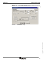
1
User Manual
TesiP@n Graphics Panel
Part number:
80 860.560
Version:
1
Revision:
0
Date:
03.02.2003
Valid for:
TP057x-xx/01xxxxxx
TP104x-xx/01xxxxxx
TP121x-xx/01xxxxxx
TP151x-xx/01xxxxxx
TesiP@n Graphics Panel
Date
03.02.2003
Modifications
First edition
This manual, including all illustrations contained herein, is copyright protected. Use of this manual by any third
party in departure from the copyright provision is forbidden. No part of this manual may be reproduced, translated or electronically or photographically archived or altered without the express written consent from Sütron
electronic GmbH. Violations shall be cause for damage liablility.
Sütron electronic reserves the right to make any changes that contribute to technical improvement.
/1-0-03.02.2003/ © Copyright by Sütron electronic GmbH
GP_eng_V1
Revision
0
TesiP@n Graphics Panel
Table of Contents
1
Important Notes ....................................................................................................... 1-3
1.1
Symbols .................................................................................................... 1-3
1.2
Safety Notes ............................................................................................. 1-3
1.2.1
1.3
2
2.1.1
Soft Keyboard ...................................................................................... 1-9
Calibrating the Touch Screen ................................................................. 1-12
3.1.1
Defining the Double-Tap Settings ...................................................... 1-12
3.1.2
Calibrating the Touch Screen ............................................................ 1-12
3.2
/1-0-03.02.2003/ © Copyright by Sütron electronic GmbH
GP_eng_V1
Help Keys.................................................................................................. 1-9
Configuration with the Servicetool ......................................................................... 1-11
3.1
4
Target Group............................................................................................. 1-4
Commissioning ........................................................................................................ 1-5
2.1
3
Intended Use ....................................................................................... 1-3
Configuring the Network ......................................................................... 1-14
3.2.1
Configuring the Adapter ..................................................................... 1-14
3.2.2
Entering the User Name and Password ............................................ 1-15
3.2.3
Entering the Computer Name ............................................................ 1-16
3.2.4
Creating a Host List ........................................................................... 1-16
3.3
Configuring the Soft Keyboard................................................................ 1-17
3.4
Setting the Date and Time ...................................................................... 1-19
3.5
Configuring the Display........................................................................... 1-21
3.6
Viewing the Process List......................................................................... 1-22
3.7
System Info ............................................................................................. 1-23
3.8
Setting up the Password ......................................................................... 1-24
3.9
Activating/Deactivating the Visualization ................................................ 1-25
Applications ........................................................................................................... 1-26
4.1
Visualizing with zenOn............................................................................ 1-27
4.1.1
Setting the Screen Resolution for the Operating Device ................... 1-27
4.1.2
Specifying the Start-up Screen .......................................................... 1-28
4.1.3
Setting-up the Remote Connection.................................................... 1-29
4.1.4
Loading the Visualization Application into the Device ....................... 1-30
4.1.4.1
Loading the Visualization by Remote Connection ....................................................1-30
4.1.5
Deleting the Visualization from the Compact Flash Card .................. 1-31
4.2
Visualizing with WEB Studio ................................................................... 1-32
4.2.1
Defining the Screen Resolution of the Operating Device .................. 1-32
4.2.2
Project Settings.................................................................................. 1-35
4.2.3
Setting-up the Remote Connection.................................................... 1-36
4.2.3.1
Loading the Visualization Application by Remote Control ........................................1-36
1
Table of Contents
TesiP@n Graphics Panel
4.2.4
Deleting the Visualization from the Compact Flash Card................... 1-38
Index ....................................................................................................................... A-1
B
List of Connecting Cables ....................................................................................... B-1
/1-0-03.02.2003/ © Copyright by Sütron electronic GmbH
GP_eng_V1
A
2
TesiP@n Graphics Panel
1
Important Notes
Important Notes
1.1
Symbols
The symbols in this manual are used to draw your attention on notes and dangers.
Danger
This symbol is used to refer to instructions which, if ignored or not carefully followed could result in personal injury.
Notes
This symbol indicates application tips or supplementary notes.
Reference to source of information
This symbol refers to detailed sources of information on the current topic.
1.2
–
Read this manual carefully before using the operating device. Keep this manual
in a place where it is always accessible to all users.
–
Proper transportation, handling and storage, placement and installation of this
product are prerequisites for its subsequent flawless and safe operation.
–
This user manual contains the most important information for the safe operation
of the device.
–
The user manual, in particular the safety notes, must be observed by all personnel working with the device.
–
Observe the accident prevention rules and regulations that apply to the operating
site.
–
Installation and operation must only be carried out by qualified and trained personnel.
1.2.1
/1-0-03.02.2003/ © Copyright by Sütron electronic GmbH
GP_eng_V1
Safety Notes
Intended Use
–
The device is designed for use in the industry.
–
The device is state-of-the art and has been built to the latest standard safety requirements. However, dangerous situations or damage to the machine itself or
other property can arise from the use of this device.
–
The device fulfills the requirements of the EMC directives and harmonized European standards. Any modifications to the system can influence the EMC behavior.
This is a class A device. This device may cause radio interference in residential areas. In this case, the user may be required to introduce appropriate countermeasures, and to bear the cost of same.
1-3
Important Notes
TesiP@n Graphics Panel
1.3
Target Group
All configuration, programming, installation, commissioning, operating and maintenance work in connection with the automation system must be performed by trained
personnel only (e.g. qualified electricians, electrical engineers, etc.).
The configuration and programming personnel must be familiar with the safety concepts of automation technology.
The operating personnel must have been trained in handling the controller and be
familiar with the operating instructions.
/1-0-03.02.2003/ © Copyright by Sütron electronic GmbH
GP_eng_V1
The installation, commissioning and maintenance personnel must have an education
which entitles them to work on automation systems.
1-4
TesiP@n Graphics Panel
2
Commissioning
Commissioning
Comission the device as described in the chapter on Mounting and Commissioning of the user manual for the device.
After applying the supply voltage, the operating device launches the BootLoader
from the internal Flash memory. During this process, the status LEDs keep flashing
at short intervals.
5310
When the boot process is complete, the following start-up screen appears:
Figure 2-1
Start-up screen
/1-0-03.02.2003/ © Copyright by Sütron electronic GmbH
GP_eng_V1
1. Tap the Start button.
1-5
Commissioning
TesiP@n Graphics Panel
5320
The dialog containing the license agreement opens. You need to accept the license
agreement to be able to operate the device:
Figure 2-2
EULA dialog
2. To accept the license agreement, tap the Accept button. Or:
3. If you do not want to accept the license agreement, tap the Ignore button. This
will take you back to the start-up screen.
Figure 2-3
1-6
Configuration screen
/1-0-03.02.2003/ © Copyright by Sütron electronic GmbH
GP_eng_V1
5330
If you accepted the license agreement, the configuration screen appears after a short
period of time:
TesiP@n Graphics Panel
Commissioning
5440
The service tool appears along with the configuration screen.
Figure 2-4
Servicetool window
To open the service tool (if it does not open automatically), carry out the following
steps:
1. Tap the Configure button.
You can use the service tools to configure the operating device.
The most important settings initially are the network and the operating mode settings.
Note that you only need to configure the network if you are not using DHCP service!
If you are using DHCP service, you can skip items 1. to 3.
To start network configuration, carry out the following steps:
1. Tap the Network icon.
2. Change the network settings.
See „Configuring the Network“ on page 1-14.
3. Tap OK to confirm all settings.
/1-0-03.02.2003/ © Copyright by Sütron electronic GmbH
GP_eng_V1
At this point, the network settings have not been saved yet! To save the settings,
you need to tap either the Save or the Exit button in the Servicetool window! If
you tap Exit, make sure you tap Yes in the following dialog to activate the saving
process!
You need to reboot the device in order for the new network settings to become effective!
To do so, press the Reset switch on the rear of the device. Use a thin object (for
example a ballpoint pen) to actuate this switch.
After the device has been booted, the configuration screen is displayed again.It continues to appear until you define the operating mode - after which it will no longer be
displayed.
4. Tap the Visu icon to select the operating mode for the operating device.
See „Activating/Deactivating the Visualization“ on page 1-25.
1-7
Commissioning
TesiP@n Graphics Panel
If your Compact Flash card contains a complete project which you want to make use
of immediately, select the operating mode Standard. The project is started from the
Compact Flash Card and you will see the first screen of the visualization application.
If you are still in the phase of developing the visualization application and you want
to test it, select the operating mode Development. The configuration screen and the
Visu dialog are closed. The Windows CE desktop is displayed.
On the desktop you will see icons for
–
the Recycle Bin,
–
the Explorer (My Computer) and
–
the Pocket Internet Explorer (Internet Explorer).
/1-0-03.02.2003/ © Copyright by Sütron electronic GmbH
GP_eng_V1
The remote connection (transport service) program is started automatically.
1-8
TesiP@n Graphics Panel
Commissioning
2.1
Help Keys
Use this key to show a soft keyboard. To hide the keyboard, press the key again.
Use this key to open the Task Manager in order to change to another task or use this
key to close the Task Manager. When you press this key again, the dialog for changing to another task is closed.
Use this key to open the Service tool. To exit the Service tool, press the key again.
Use this key to open the context menu, which can usually be reached by pressing
the right mouse button.
Use this key to set the contrast and the brightness.
To define the contrast / brightness setting, use the key combinations shown below
as follows:
To increase the
contrast:
To increase the
brightness:
To reduce the
contrast:
To reduce the brightness:
2.1.1
Soft Keyboard
/1-0-03.02.2003/ © Copyright by Sütron electronic GmbH
GP_eng_V1
4930
When you call-up the soft keyboard, it initially displays only small (lower case) characters, numbers and those special characters that are available on a hardware keyboard when the Shift key is not pressed.
Figure 2-5
Soft keyboard with small (lower case) characters
1-9
Commissioning
TesiP@n Graphics Panel
4940
When you tab the Shift key, the software keyboard provides large (upper case) characters and those special characters that are available on a hardware keyboard when
the Shift key is pressed.
Soft keyboard with large (upper case) characters
/1-0-03.02.2003/ © Copyright by Sütron electronic GmbH
GP_eng_V1
Figure 2-6
1-10
TesiP@n Graphics Panel
3
Configuration with the Servicetool
Configuration with the Servicetool
5440
Launch the Servicetool to be able to configure the device.
Figure 3-1
Servicetool window
/1-0-03.02.2003/ © Copyright by Sütron electronic GmbH
GP_eng_V1
The icons stand for the following configuration options:
Stylus
To configure the touch screen
Network
To configure the network
Input Panel
To configure the soft keyboard
Date/Time
To set the date and time
Display
To set the contrast and/or brightness
Processes
To view process data
Systeminfo
To view device data
Password
To enter the password
Visu
To set the operating mode
Save
To save changes
Exit
To save changes and exit the service tool
Tap the icon to start the configuration. After finishing the configuration, you will return
to the Servicetool window.
At this point, the network settings have not been saved yet! To save the settings,
you need to tap either the Save or the Exit button in the Servicetool window! If
you tap Exit, make sure you tap Yes in the following dialog to activate the saving
process!
You need to reboot the device in order for the new network settings to become effective!
To do so, press the Reset switch on the rear of the device. Use a thin object (for
example a ballpoint pen) to actuate this switch.
1-11
Configuration with the Servicetool
3.1
TesiP@n Graphics Panel
Calibrating the Touch Screen
1. Tap the Service tool key.
2. Then tap the Stylus icon.
4860
The Stylus Properties dialog opens.
Figure 3-2
Stylus Properties dialog, Double-Tap tab
The Double-Tap index card is displayed by default.
3.1.1
Defining the Double-Tap Settings
To test the settings defined for the „double-tap“, tap the test icon twice.
To change the current double-tap settings, tap the checkered pattern (grid) twice.
The speed and the physical distance between the two taps will be recorded as the
new double-tap settings.
3.1.2
Calibrating the Touch Screen
Figure 3-3
Stylus Properties dialog, Calibration tab
To change the calibration settings of the touch screen carry out the following steps:
1. Tap the Recalibrate button to start the calibration process.
2. Tap and hold the center of the cross (precisely the center) until the cross changes
its position.
1-12
/1-0-03.02.2003/ © Copyright by Sütron electronic GmbH
GP_eng_V1
4870
Open the Calibration index card.
TesiP@n Graphics Panel
Configuration with the Servicetool
/1-0-03.02.2003/ © Copyright by Sütron electronic GmbH
GP_eng_V1
The calibration process is complete when the cross disappears. At this point, the
changes still need to be saved. The device waits 30 seconds for you to tap the touch
screen for this purpose. If you do not tap the touch screen within this time period, the
new settings will not be stored. In this case, the device continues to work with the old
settings.
1-13
Configuration with the Servicetool
TesiP@n Graphics Panel
3.2
Configuring the Network
3.2.1
Configuring the Adapter
The first part of the network configuration concerns the setting of the network
adapter. The operating device has an integrated network adapter, which cannot be
replaced.
To configure the network adapter carry out the following steps:
1. Tap the Service tool key.
2. Then tap the Network icon.
4880
The Network Configuration dialog opens.
Figure 3-4
Network Configuration dialog, Adapters index card
1. Select the network adapter LAN90001.
2. Tap the Properties button to change the adapter settings.
Figure 3-5
Network Configuration dialog, IP Address index card
The IP Address index card is displayed by default.
3. Specify whether you want the DHCP service to assign an IP address to the device dynamically.
4. If you are unable to use DHCP, enter at least one fixed IP address and one subnet mask.
The configuration for name servers is not urgently necessary. If you are using a
DHCP service or fixed IP addresses you can pass the following configuration steps.
1-14
/1-0-03.02.2003/ © Copyright by Sütron electronic GmbH
GP_eng_V1
4890
The dialog for specifying the adapter settings opens.
TesiP@n Graphics Panel
Configuration with the Servicetool
4900
5. Open the Name Servers index card.
Figure 3-6
Network Configuration dialog, Name Servers index card
6. If you do not have the DHCP service assign the IP addresses dynamically, enter
the IP address of the DNS server and of the WINS server into this index card.
7. Click OK to close the dialog.
For the IP address settings to become active, the device must be restarted!
The Adapters index card is displayed again.
3.2.2
Entering the User Name and Password
To enter the user name which you use to log on to an enabled network drive, carry
out the following steps:
/1-0-03.02.2003/ © Copyright by Sütron electronic GmbH
GP_eng_V1
4910
1. Open the Identification index card.
Figure 3-7
Network Configuration dialog, Identification index card
2. Enter your user name into the User name field.
3. Enter your password into the Password field.
4. Enter the name of the domain into the Domain field.
The user name, password and domain information are stored in the device. Saving this information represents a general security risk!
1-15
Configuration with the Servicetool
3.2.3
TesiP@n Graphics Panel
Entering the Computer Name
To assign the device a unique name with which it will be represented on the Microsoft
network, carry out the following steps:
4920
1. Open the Computer Name index card.
Figure 3-8
Network Configuration dialog, Computer Name index card
2. Enter a name for the device into the Name field.
To be able to connect to the network drive, you first need to change the preset name.
Your own IP address of the operating device appears in the IP address field.
3.2.4
Creating a Host List
If a name server is not available, you can create a hosts list so that an assignment
between computer names and IP address is possible.
To manage the host list carry out the following steps:
Figure 3-9
Network Configuration dialog, Hostslist index card
2. Tap the New button to specify a new host.
1-16
/1-0-03.02.2003/ © Copyright by Sütron electronic GmbH
GP_eng_V1
4970
1. Open the Hostslist index card.
TesiP@n Graphics Panel
Configuration with the Servicetool
4980
The Host entry dialog opens.
Figure 3-10
Host Entry dialog
3. Enter the new host name into the Host name field.
4. Enter the associated IP address into the IP Address fields.
5. Tap OK to confirm the entered information.
The Hostslist index card is displayed again.
6. To delete a selected entry from the host list, tap the Delete button.
7. To edit a selected host list entry, tap the Edit button.
8. Then tap OK to confirm your settings.
At this point, the entered network settings have not been saved yet! To save the
settings you need to tap either the Save button or the Exit button in the Servicetool window. If you tab on the Exit button a secondary dialog opens where you
have to activate the saving procedure with Yes!
3.3
Configuring the Soft Keyboard
1. Tap the Service tool key.
2. Then tap the Input Panel icon.
/1-0-03.02.2003/ © Copyright by Sütron electronic GmbH
GP_eng_V1
4950
The Input Panel Properties dialog opens.
Figure 3-11
Input Panel Properties dialog
In the Current input method field, you see the current selection for the soft keyboard input device. These settings cannot be changed.
1. Tap the Options button.
1-17
Configuration with the Servicetool
TesiP@n Graphics Panel
4960
The Soft Keyboard Options dialog opens.
Figure 3-12
Soft Keyboard Options dialog
The dialog displays the current settings for the soft keyboard.
2. Select the Large keys radio button if you want the keyboard to be displayed with
large (upper case) keys.
3. Select the Small keys radio button if you want the keyboard to be displayed with
small (lower case) keys.
4. Tick the Use gestures... check box to replace the functions of the space, backspace, Enter and Shift keys by carrying out specific gestures. In this case you
would have to do the following:
–
To enter the character which a key stands for, tap the key.
–
To enter the character assigned to the shift function, tap the key and carry out an
upward sweeping movement.
–
To enter a space, tap any key and carry out a sweeping movement to the right.
–
To move one digit to the left and to delete the digit in the process, tap any key
and carry out a sweeping movement to the left.
–
To actuate the Enter key, tap any key and carry out a downward sweeping movement.
5. Tap OK to confirm your settings.
The Input Panel Properties dialog appears again.
/1-0-03.02.2003/ © Copyright by Sütron electronic GmbH
GP_eng_V1
6. Complete your settings by tapping OK.
1-18
TesiP@n Graphics Panel
3.4
Configuration with the Servicetool
Setting the Date and Time
1. Tap the Service tool key.
2. Then tap the Date/Time icon.
4990
The Date/Time Properties dialog opens.
Figure 3-13
Date/Time Properties dialog, Time index card
The Time index card is displayed by default.
The current time setting is shown in the center section of the index card.
To change the time setting, carry out the following steps:
1. To set the hours, tap the Hour+ and Hour- buttons.
2. To set the minutes, tap the Min+ and Min- buttons.
3. To set the seconds, tap the Sec+ and Sec- buttons.
4. To switch to summer time, tick the Daylight savings time check box.
To change the date setting, carry out the following steps:
/1-0-03.02.2003/ © Copyright by Sütron electronic GmbH
GP_eng_V1
5010
1. Open the Date index card.
Figure 3-14
Date/Time Properties dialog, Date index card
The calender page shows the current date setting.
2. To set the month and year, tap the right and left arrows.
3. To set the day, tap the number for the corresponding day.
1-19
Configuration with the Servicetool
TesiP@n Graphics Panel
To change the time zone setting, carry out the following steps:
5030
1. Open the Timezone index card.
Figure 3-15
Date/Time Properties dialog, Timezone index card
2. To open a list with the time zones, tap the down arrow.
3. To navigate to the appropriate time zone, tap the up and down arrows.
4. To select a time zone, tap the name of the appropriate time zone.
5. Tap OK to confirm your settings.
/1-0-03.02.2003/ © Copyright by Sütron electronic GmbH
GP_eng_V1
Date and time settings are saved only on devices that are equipped with a battery.
1-20
TesiP@n Graphics Panel
3.5
Configuration with the Servicetool
Configuring the Display
1. Tap the Service tool key.
2. Then tap the Display icon.
5040
The Display dialog opens.
Figure 3-16
Display dialog, Brightness index card
The Brightness index card is displayed by default.
The current brightness setting for the display is shown in the center section of the
index card.
To change the brightness setting, carry out the following steps:
1. To increase the brightness, tap the + button.
2. To decrease the brightness, tap the - button.
To change the contrast setting, carry out the following steps:
/1-0-03.02.2003/ © Copyright by Sütron electronic GmbH
GP_eng_V1
5050
1. Open the Contrast index card.
Figure 3-17
Display dialog, Contrast index card
2. To increase the contrast, tap the + button.
3. To decrease the contrast, tap the - button.
4. Tap OK to confirm your settings.
1-21
Configuration with the Servicetool
3.6
TesiP@n Graphics Panel
Viewing the Process List
The process list displays a list of all current processes and either of the modules or
of the threads.
1. Tap the Service tool key.
2. Then tap the Processes icon.
5060
The ProcessViewer window opens.
Figure 3-18
ProcessViewer window
This window displays all currently executed processes.
To refresh the process screen, carry out the following steps:
1. Open the Processes menu.
2. Tap the Refresh menu item.
You can also refresh the screen by tapping the Refresh icon.
To have the screen refreshed automatically, carry out the following steps:
1. Open the Processes menu.
2. Tap the Update (auto.) menu item.
To display the modules, carry out the following steps:
1. Open the View menu.
2. Tap the Modules menu item.
A dot is displayed next to the Modules menu item.
To display the threads, carry out the following steps:
1. Open the View menu.
2. Tap the Threads menu item.
A dot is displayed next to the Threads menu item.
To exit the process list, carry out the following steps:
1. Open the Processes menu.
2. Tap the Exit menu item.
1-22
/1-0-03.02.2003/ © Copyright by Sütron electronic GmbH
GP_eng_V1
A dot is displayed next to the Update (auto.) menu item.
TesiP@n Graphics Panel
Configuration with the Servicetool
3.7
System Info
1. Tap the Service tool key.
2. Then tap the Systeminfo icon.
5090
The Systeminfo window opens.
Figure 3-19
Systeminfo window, Device Data index card
The Device Data index card is displayed by default.
The following information is shown on this card:
–
OS Version = Operating system Kernel
–
OS Date = Date when Kernel was created
–
Serial = Serial number of the device
–
MAC Address = MAC address of the LAN interface
To check the status of the battery, carry out the following steps:
/1-0-03.02.2003/ © Copyright by Sütron electronic GmbH
GP_eng_V1
5100
1. Open the Battery index card.
Figure 3-20
Systeminfo window, Battery index card
1-23
Configuration with the Servicetool
TesiP@n Graphics Panel
The following status can be displayed:
Battery OK
Battery is in good condition
No battery found
Battery is drained
or
no battery attached
3.8
Setting up the Password
The password protection becomes active when the operator attempts to call up the
Service tool or the Task Manager from within the running application.
The TesiP@n is provided with password protection ex-works!
The password is „x“.
To set up the password carry out the following steps:
1. Tap the Service tool key.
2. Then tap the Password icon.
5110
The Password dialog opens.
Figure 3-21
Password dialog
3. Enter a password into the Password field.
4. Enter the same password once more into the Confirm password field.
5. Tick the Enable password protection check box.
1-24
/1-0-03.02.2003/ © Copyright by Sütron electronic GmbH
GP_eng_V1
An asterisk will be displayed for each entered character!
TesiP@n Graphics Panel
Configuration with the Servicetool
3.9
Activating/Deactivating the Visualization
Launch the Visu software to place the operating device into either the operating
mode Standard or the operating mode Development.
Operating mode
Standard
Use the Standard operating mode to start the Runtime of the visualization software.
The project to be executed must be stored on the Compact Flash card plugged into
the device.
The Windows CE user interface is not started. The Servicetool key and the Taskmanager key are password protected.
The TesiP@n is factory-set to use password protection !
The password is „x“.
Operating mode
Development
Use the Development operating mode to start the Transport Service of the visualization software.
The Windows CE user interface is started also. The Servicetool key and the Taskmanager key are not password protected.
After a reboot, the device will be in the operating mode which was active before the
device was rebooted.
To start the Visu function, carry out the following steps:
1. Tap the Servicetool key.
2. Then tap the Visu icon.
/1-0-03.02.2003/ © Copyright by Sütron electronic GmbH
GP_eng_V1
5450
This opens the Visu dialog.
Figure 3-22
Visu dialog
3. Tap either the Standard button or the Development button to activate the desired operating mode.
1-25
Applications
4
TesiP@n Graphics Panel
Applications
TesiP@n graphic panels are used to display process variables and process sequences graphically and to change them, if necessary.
You create the visualization application on your PC using a corresponding editing
software. TesiP@n graphic panels hava a Runtime preinstalled. Therefore you simply need to load the visualization application into the device.
Described below is how you load the visualization application into the TesiP@n device, define device specific settings and launch the visualization application. A description of the visualization application functionality is outside of the scope of this
manual!
/1-0-03.02.2003/ © Copyright by Sütron electronic GmbH
GP_eng_V1
For further information on the editing software see the online help or the documentation supplied by the manufacturer.
1-26
TesiP@n Graphics Panel
Applications
4.1
Visualizing with zenOn
To keep the size of this manual compact, it is assumed that you are already familiar
with the COPA-DATA software zenOn.
4.1.1
Setting the Screen Resolution for the Operating Device
You can specify the screen resolution of your operating device in order to have the
visualization screens scaled to fit the size of the target hardware when you create
them. If you do not have the size fitted, the device will zoom the screen as necessary.
But the results may not be optimal.
To set the screen resolution, carry out the following steps:
1. Launch the zenOn editor.
2. Open a project.
3. Select Project Configuration/Monitor Administration from the File menu.
5760
The Screen Configuration dialog opens.
Figure 4-1
Screen Configuration dialog
4. Enter the width and the height for the display of your TesiP@n device into the
Screen Size field.
/1-0-03.02.2003/ © Copyright by Sütron electronic GmbH
GP_eng_V1
Table 4-1
Sizes of TesiP@n displays
TesiP@n
Width
Height
TP057
320
240
TP104
640
480
TP121
800
600
TP151
1024
768
5. Tap OK to confirm your settings.
1-27
Applications
TesiP@n Graphics Panel
4.1.2
Specifying the Start-up Screen
After booting the operating device, the screen you specified in the project management function as the start-up screen of your visualization application appears.
To specify the start-up screen, carry out the following steps:
1. Launch the zenOn editor.
2. Open a project.
3. Select Project Configuration/Project from the File menu.
5770
The Configuration Project dialog opens.
Figure 4-2
Configuration Project dialog
4. Open the Runtime index card, provided it is not already open.
5. Enter the name of the start-up screen into the Starting Picture field.
/1-0-03.02.2003/ © Copyright by Sütron electronic GmbH
GP_eng_V1
6. Tap OK to confirm your settings.
1-28
TesiP@n Graphics Panel
Applications
4.1.3
Setting-up the Remote Connection
We recommend using the Ethernet cable for connecting to the operating device. This
provides the fastest means of exchanging data and remote control of the device.
To set-up the remote connection, carry out the following steps:
1. Launch the zenOn editor.
2. Open a project.
3. Select Project Configuration/Project from the File menu.
5780
The Configuration Project dialog opens.
Figure 4-3
Configuration Project dialog
4. Open the Remote Transport index card.
5. Enter: „Target = drive and path of the operating device“ into the row containing
the „Basic project path“ description of the table.
/1-0-03.02.2003/ © Copyright by Sütron electronic GmbH
GP_eng_V1
Target = Memory
card in the device:
When specifying the target, it is of no relevance which letter you use for the memory
card. Attention must, however, be paid to the path name. The default path is „\Storage Card\Data“.
The other path names in the table are relative paths referring to the basic path which
you can use as is (no changes necessary).
6. Enter the IP address of the TesiP@n device into the Configuration Parameters
field.
When you enter the IP address, make sure it complies with the syntax „HOST = IP
address“. The IP address is marked on the operating device.
See „Entering the Computer Name“ on page 1-16.
1-29
Applications
Target = Memory
card in a CF card
reading device
TesiP@n Graphics Panel
The drive letter you specify for the target must be entered exactly the same as listed
in the Explorer. The folder name must be „\Data“.
7. Enter „HOST = localhost“ into the Configuration Parameters field.
8. Tap OK to confirm your settings.
4.1.4
Loading the Visualization Application into the Device
The visualization application must be located on the Compact Flash card. When the
visualization application is started, the device automatically accesses the memory
card and launches the application stored there.
4.1.4.1
Loading the Visualization by Remote Connection
To load the visualization application by remote connection, use the Ethernet cable
for connecting the TesiP@n device to an existing network.
To load the visualization application into the device, carry out the following steps:
1. Start-up the operating device.
2. Switch the device to the operating mode Development, if it is not already startedup in this mode.
See „Activating/Deactivating the Visualization“ on page 1-25.
5130
The Transport Service program is launched.
Transport Service program
The Transport Service program is active immediately. The Configuration field displays the communication connection setting. If you want to change the setting, first
tap the Stop button.
3. Start the zenOn editor on the PC.
4. Open a project.
5. Create the Runtime files for the open project.
6. Click the icon „Establishing remote connection“ in the toolbar.
After the connection has been successfully established, the neighboring icons become active.
7. Click the icon „Remote transport all project files“ in the toolbar.
1-30
/1-0-03.02.2003/ © Copyright by Sütron electronic GmbH
GP_eng_V1
Figure 4-4
TesiP@n Graphics Panel
Applications
You can monitor the status of the loading process in the Output Editor window. After
the visualization application has been successfully loaded, you can activate the
Standard operating mode.
See „Activating/Deactivating the Visualization“ on page 1-25.
4.1.5
Deleting the Visualization from the Compact Flash Card
The visualization application is stored in the \Storage Card\Data\Project name path
of a Compact Flash card.
If you want to delete all visualization data, delete the folder Project name and its contents.
To delete the folder, carry out the following steps:
1. Double-tap the icon My Computer on the desktop.
The Windows Explorer opens.
2. Double-tap Storage Card.
3. Double-tap Data.
4. Select the folder which has the same name as the project.
/1-0-03.02.2003/ © Copyright by Sütron electronic GmbH
GP_eng_V1
5. Tap the icon Delete in the toolbar.
1-31
Applications
TesiP@n Graphics Panel
4.2
Visualizing with WEB Studio
To keep the size of this manual compact, it is assumed that you are already familiar
with the Indusoft software Web Studio.
4.2.1
Defining the Screen Resolution of the Operating Device
You can specify the screen resolution of your TesiP@n device so that the screens of
the visualization application are scaled to fit the target hardware size when they are
created. You can specify this information when you create a new project or later as
„screen attributes“! If you do not have the size scaled, the screen may be cropped
(only a part of the screen will be displayed) or it may only fill the top left corner of the
display.
To define the screen resolution setting, carry out the following steps:
1. Launch the InduSoft software Web Studio.
2. Select New from the File menu.
Figure 4-5
New dialog
3. Enter a name for the new project into the Application name field.
4. Select the name of the Runtime which you purchased with the device (CEView
Lite or CEView Standard) in the list Target platform.
5. Tap OK to confirm your settings.
1-32
/1-0-03.02.2003/ © Copyright by Sütron electronic GmbH
GP_eng_V1
5510
The New dialog opens.
TesiP@n Graphics Panel
Applications
5520
The Project Wizard dialog opens.
Figure 4-6
Project Wizard dialog
6. Select the resolution for the TesiP@n device from the selection list Resolution.
Table 4-2
Size of TesiP@n displays
TesiP@n
Width
Height
TP057
320
240
TP104
640
480
TP121
800
600
TP151
1024
768
7. Define all other settings for the new project.
/1-0-03.02.2003/ © Copyright by Sütron electronic GmbH
GP_eng_V1
8. Tap OK to confirm your settings.
1-33
Applications
TesiP@n Graphics Panel
5530
When you insert a new screen into the project, this screen automatically has the resolution preset in the Size field of the following dialog.
Screen Attributes dialog
/1-0-03.02.2003/ © Copyright by Sütron electronic GmbH
GP_eng_V1
Figure 4-7
1-34
TesiP@n Graphics Panel
4.2.2
Applications
Project Settings
The taskbar of Windows CE takes up valuable display space of a visualization application, which is why it is hidden in most cases. You can hide the Windows CE taskbar
by activating the corresponding option in the project settings. Note that the factorypreinstalled Windows CE is already set to hide the taskbar in the operating mode
Standard. This means that activating this function again in the project settings may
cause malfunctions!
To deactivate the function in Web Studio responsible for hiding the taskbar, carry out
the following steps:
1. Launch the InduSoft software Web Studio.
2. Select Settings from the Project menu.
5540
The Project Settings dialog opens.
Figure 4-8
Project Settings dialog, Runtime Desktop index card
3. Open the Runtime Desktop index card.
/1-0-03.02.2003/ © Copyright by Sütron electronic GmbH
GP_eng_V1
4. Unselect the Hide Taskbar check box if it is selected.
5. Enter the name of the screen which you want to be displayed as the first screen
of the project into the Startup Screen field.
6. Tap OK to confirm.
1-35
Applications
TesiP@n Graphics Panel
4.2.3
Setting-up the Remote Connection
We recommend using the Ethernet cable for connecting to the TesiP@n device. This
provides the fastest means of exchanging data and remote control of the device.
To set-up the remote connection, carry out the following steps:
1. Launch the InduSoft software Web Studio.
2. Open a project.
3. Select Execution Environment from the Project menu.
5550
The Execution Environment dialog opens.
Figure 4-9
Execution Environment dialog
4. Open the Target index card, if it has not opened automatically.
5. Select the Network IP check box.
6. Enter the IP address of the TesiP@n device into the field next to the check box.
See „Entering the Computer Name“ on page 1-16
4.2.3.1
Loading the Visualization Application by Remote Control
To load the visualization application into the device, carry out the following steps:
1. Start-up the TesiP@n device.
2. Switch the device to the operating mode „Development“, if it has not already
started up in this mode.
See „Activating/Deactivating the Visualization“ on page 1-25
1-36
/1-0-03.02.2003/ © Copyright by Sütron electronic GmbH
GP_eng_V1
To load the visualization application by remote connection, use the Ethernet cable
for connecting the TesiP@n device to an existing network.
TesiP@n Graphics Panel
Applications
5560
The Remote Agent is started.
Figure 4-10
Transport Service program
The Remote Agent software becomes active immediately.
3. Launch the InduSoft software Web Studio on the PC.
4. Open a project.
5. Select Execution Environment from the Project menu.
5550
The Execution Environment dialog opens.
/1-0-03.02.2003/ © Copyright by Sütron electronic GmbH
GP_eng_V1
Figure 4-11
Execution Environment dialog
6. Open the Target index card, if it has not opened automatically.
7. Click the Connect button.
1-37
Applications
TesiP@n Graphics Panel
After the connection has been established, the Status field displays „Connected to
CEView v5.1“.
5570
8. Open the Application index card.
Figure 4-12
Execution Environment dialog, Application index card
9. Click the Send To Target button.
A Sending To Target window appears temporarily allowing you to monitor how the
loading process progresses. You can use the Run button or the Stop button to remotely start and stop the operating device so you can test the visualization application.
If the visualization test was successful, you can activate the operating mode Standard on the operating device.
See „Activating/Deactivating the Visualization“ on page 1-25.
4.2.4
Deleting the Visualization from the Compact Flash Card
If you want to delete all visualization data, delete the folder Project name and its contents.
To delete the folder, carry out the following steps:
1. Double-tap the My Computer icon on the desktop.
The Windows Explorer opens.
2. Double-tap Storage Card.
3. Double-tap Data.
4. Select the folder with the name of the project.
5. Tap the Delete icon in the toolbar.
1-38
/1-0-03.02.2003/ © Copyright by Sütron electronic GmbH
GP_eng_V1
The visualization application is stored in the \Storage Card\Data\Project name
folder of the Compact Flash card.
TesiP@n Graphics Panel
Index
A Index
B
P
Battery............................................................. 1-23
Brightness ....................................................... 1-21
Password ........................................................ 1-15
Process List..................................................... 1-22
C
R
Calibrating the Touch Screen ......................... 1-12
Computer Name.............................................. 1-16
Contrast .......................................................... 1-21
Current Input Method ...................................... 1-17
Refresh............................................................ 1-22
Runtime........................................................... 1-25
S
Date ................................................................ 1-19
Date/Time ....................................................... 1-19
Daylight Savings Time .................................... 1-19
Defining the Double-Tap Settings ................... 1-12
Device Data .................................................... 1-23
DHCP.............................................................. 1-14
DNS ................................................................ 1-15
Domain............................................................ 1-15
Safety Notes...................................................... 1-3
Serial ............................................................... 1-23
Servicetool ...................................................... 1-11
Small (Lower Case) Keys................................ 1-18
Soft Keyboard ................................................... 1-9
Soft Keyboard Options .................................... 1-18
Summer Time.................................................. 1-19
Symbols
General ..................................................... 1-3
System Info ..................................................... 1-23
E
T
Enable Password Protection........................... 1-24
Target Group..................................................... 1-4
Threads ........................................................... 1-22
Time ................................................................ 1-19
Timezone ........................................................ 1-20
Transport Service............................................ 1-25
D
H
Hostslist .......................................................... 1-16
I
Input Panel Properties .................................... 1-17
Intended Use..................................................... 1-3
IP Address ...................................................... 1-14
Your Own................................................ 1-16
K
U
Use Gestures .................................................. 1-18
User Name ...................................................... 1-15
W
WINS............................................................... 1-15
Key
/1-0-03.02.2003/ © Copyright by Sütron electronic GmbH
GP_eng_V1
ABC .......................................................... 1-9
Contrast / Brightness ................................ 1-9
Hot Key ..................................................... 1-9
New Task.................................................. 1-9
Right Mouse Button .................................. 1-9
L
Large (Upper Case) Keys ............................... 1-18
M
MAC Address.................................................. 1-23
Module ............................................................ 1-22
N
Name Server................................................... 1-15
Network Adapter ............................................. 1-14
O
OS Date .......................................................... 1-23
OS Version...................................................... 1-23
A-1
/1-0-03.02.2003/ © Copyright by Sütron electronic GmbH
GP_eng_V1
Index
A-2
TesiP@n Graphics Panel
TesiP@n Graphics Panel
List of Connecting Cables
B List of Connecting Cables
Preassembled cables are available for the connections listed below.
When ordering a cable, please enter the cable length in place of ’xxx’ .
Example:
Cable for ABB CS31 with a length of 5.5 meters = 88 167.055
Table A-1
Connecting cable
Manufacturer
Protocol
Interface
Part Number
Bosch CL200/300/500
BUEP19/19E
TTY (COM2)
88 144.xxx
Siemens S5 PG
AS511
TTY (COM2)
88 133.xxx
/1-0-03.02.2003/ © Copyright by Sütron electronic GmbH
GP_eng_V1
You can not conclude from the fact that a cable is listed that ZenOn or Web Studio
actually support the corresponding protocol!
B-1
List of Connecting Cables
B.1
TesiP@n Graphics Panel
Bosch BUEP19/BUEP19E
Operating Device
Transmitter Active
Receiver Active
S1+
T+
S2+
R+
R-
S2-
T-
S1-
Bosch
e.g. Z301
Transmitter Passive
Receiver Passive
2480
Cable for connection to the TTY interface of the controller.
12
10
16
13
14
YE
YE
23
24
GN
GN
13
19
BN
BN
22
21
WH
WH
12
T+
T-
R+
R-
1
D-SUB
Male Connector
25-pin
D-SUB
Male Connector
25-pin
Cable for Bosch BUEP19/BUEP19E
/1-0-03.02.2003/ © Copyright by Sütron electronic GmbH
GP_eng_V1
Figure A-2
B-2
TesiP@n Graphics Panel
B.2
List of Connecting Cables
Siemens S5 PG AS511
Cable for connection to the TTY interface of the controller.
S1+
T+
S2+
R+
R-
S2-
T-
S1-
Siemens
Simatic S5
Transmitter Passive
Receiver Passive
1750
Operating Device
Transmitter Active
Receiver Active
12
10
16
13
14
YE
YE
6
24
GN
GN
7
19
BN
BN
9
21
WH
WH
2
1
1
T+
T-
R+
R-
PG
8
D-SUB
Male Connector
15-pin
D-SUB
Male Connector
25-pin
Cable for Siemens S5 PG
/1-0-03.02.2003/ © Copyright by Sütron electronic GmbH
GP_eng_V1
Figure A-3
B-3
/1-0-03.02.2003/ © Copyright by Sütron electronic GmbH
GP_eng_V1
List of Connecting Cables
B-4
TesiP@n Graphics Panel
/1-0-03.02.2003/ © Copyright by Sütron electronic GmbH
GP_eng_V1
Sütron electronic GmbH
Kurze Straße 29
D-70794 Filderstadt
Tel.:
0049 711 / 77098-0
Fax.:
0049 711 / 77098-60
E-Mail: [email protected]
Internet: www.suetron.com