1
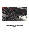
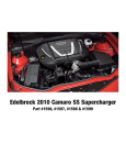
Edelbrock LS7 Corvette Supercharger
Part #1572 & 1573
Edelbrock GM LS7 Supercharger System for
2006 - 2010 Z06 Corvettes
Installation Instructions
INTRODUCTION
Thank you for purchasing the Edelbrock 7.0L GM Supercharger System for the Chevy Corvette Z06. The Edelbrock E-Force
Supercharger System for the 2006 to 2010 Corvette Z06 (not compatible with ZR1 or base models) utilizes Eaton’s new
Gen VI TVS Supercharger rotors, featuring a four lobe design with a full 160 deg. of twist for maximum flow, minimum
temperature rise, quiet operation, and the reliability for which Eaton is known. The Edelbrock Supercharger is a complete
system that maximizes efficiency and performance by minimizing air restriction into, and out of, the supercharger. This
results in maximum airflow, with minimal temperature rise and power consumption. The supercharger housing itself is
integrated into the intake manifold for a seamless design with minimal components, eliminating the possibility of vacuum
leaks between gasket surfaces. The system also utilizes a front drive, front inlet configuration giving it the shortest, least
restrictive inlet path on the market. The supercharger is inverted, expelling the air upward. Air pressure then builds in the
plenum, before being drawn down through each of two intercooler cores, oriented horizontally, next to, and below the
supercharger outlet. After passing through the intercooler cores, the air travels through the long 12” runners, which route
underneath the supercharger housing to the cylinder head ports, in a horizontal, nested configuration. The upper plenum
area is enclosed by a top cover that has been designed to provide an appealing and distinctive under-hood appearance.
This configuration allows for a compact package that can fit under the stock hood and cowl of the C6 Corvette, without
sacrificing runner length, or intercooler area. The E-Force supercharger features a uniquely styled plenum, and includes
matching side covers. The Edelbrock supercharger provides neck snapping performance that is safe to operate on a
completely stock engine. It is 50-state emissions legal, and can be had with an optional 5-year 100,000 mile warranty
so that there are no worries when installing it on a brand new car.
TOOLS AND SUPPLIES REQUIRED
Jack and Jack Stands
OR Service Lift
Panel Puller
Ratchet and Socket Set including: 7mm, 8mm, 10mm
(standard, deep and universal), 11mm, 12mm (deep),
13mm, 15mm, 18mm, 21mm (deep), 24mm
Wrenches including: 8mm, 18mm, 27mm
18mm Line Wrench
12” Ratchet Extension Bar
1/2” Breaker Bar
Flat Blade & Philips Screwdrivers
Compressed Air
Torx-20 Driver
Allen Wrenches including: 5mm, 6mm, 8mm
2” Long 6mm Allen Socket
3/8” Fuel Line Removal Tool
Torque Wrench
Needle Nose Pliers
Pliers
OR Hose Clamp Removal Tool
Pneumatic or Power Drill
Impact Wrench
Loctite 609 Retaining Compound or equivalent
O-ring Lube
Anti-sieze
Masking Tape
DT-47731 Transmission Cooler Quick Disconnect Tool
J-42188 Ball Joint Separator
J-42386-A Flywheel Holding Tool
Edelbrock LLC, 2700 California Street, Torrance, CA 90503
Toll-Free Tech Line: 1-800-416-8628 Office/Sales Line: 310-781-2222
©2010 Edelbrock LLC
Part #1572 & 1573
Page 1
Brochure #63-1572
Rev. 1/11 - AJ/mc
Edelbrock GM LS7 Supercharger System for
2006 - 2010 Z06 Corvettes
Installation Instructions
Proper installation is the responsibility of the installer. Improper installation will void the warranty and
may result in poor performance and engine or vehicle damage.
Due to the complexity of the Edelbrock E-Force Supercharging system, it is recommended that this system only be
installed by a qualified professional with access to a service lift, pneumatic tools, and a strong familiarity with
automotive service procedures. To qualify for the optional warranty, it is necessary to have this system installed by a
certified ASE technician, GM dealership, or Edelbrock approved installer. Failure to have this system installed by a
properly certified service center will void the optional warranty offered with this sytem. Please contact the Edelbrock
Technical Support department if you have any questions regarding this sytem and/or how your installer of choice will
affect any warranty coverage for which your vehicle may qualify.
Any previously installed aftermarket tuning equipment must be removed and the vehicle returned to an as
stock condition before installing the supercharger.
Any equipment that directly modifies the fuel mixture or ignition timing of the engine can cause severe engine damage
if used in conjunction with the Edelbrock E-Force Supercharger System. This includes, but is not limited to: ignition
boxes, air/fuel controllers, OBDII programmers, and any other device that modifies signals to and/or from the ECU.
Aftermarket bolt-on equipment such as underdrive pulleys or air intake kits will also conflict with the operation of the
supercharger and must be removed prior to installation. Use of any of these products with the E-Force Supercharger
could result in severe engine damage.
91 octane or higher gasoline is required at all times. If your vehicle has been filled with anything less, it
must be run until dry and refilled with 91 or higher octane gasoline twice prior to installation.
Inspect all components for damage that may have occured in transit before beginning installation. If any
parts are missing or damaged, contact Edelbrock Technical Support, not your parts distributor.
Edelbrock periodically releases improved versions of the calibration file found on the supplied handheld
programmer. Check the website to ensure you have the latest version, as described in step #209.
©2010 Edelbrock LLC
Part #1572 & 1573
Page 2
Brochure #63-1572
Rev. 1/11 - AJ/mc
Edelbrock GM LS7 Supercharger System for
2006 - 2010 Z06 Corvettes
Installation Instructions
INSTALLATION HARDWARE IDENTIFICATION GUIDE
Bag #1
(2x) - M8 Washer
(1x) - M10 x 1.5 x 65mm Hex Flange Bolt
(3x) - M8 x 1.25 x 20mm Hex Flange Bolt
(3x) - M8 x 1.25 x 90mm Hex Flange Bolt
(1x) - M10 x 1.5 x 45mm Socket Head Bolt
Bag #2
(1x) - M8 x 1.25 x 30mm Hex Flange Bolt
(3x) - M6 x 1 x 16mm Hex Flange Bolt
(6x) - 3/4” Hose Clamp
(2x) - M6 x 1 x 20mm Hex Flange Bolt
(1x) - Nylon Body Pin
(1x) - M8 x 1.25 x 25mm Hex Flange Bolt
(1x) - Lower Intercooler Reservoir Bracket
(2x) - 1/2” Hose Clamp
(2x) - 1-3/4” Worm Clamp
(Not to Scale)
(1x) - Upper Intercooler Reservoir Bracket
©2010 Edelbrock LLC
Part #1572 & 1573
Page 3
(1x) - 3/4” Worm Clamp
(Not to Scale)
Brochure #63-1572
Rev. 1/11 - AJ/mc
Edelbrock GM LS7 Supercharger System for
2006 - 2010 Z06 Corvettes
Installation Instructions
Bag #3
(8x) - M6 x 1 x 45mm Hex Flange Bolt
(11x) - M8 x 1.25 x 25mm
Countersunk Socket Head Bolt
(4x) - M6 x 1 x 12mm Socket Head Bolt
Bag #4
(1x) - GM Factory Harmonic Balancer Bolt
(1x) - M16 x 2 x 120mm Hex Bolt
Ream Hole
Drill Hole
Bolt Hole
(1x) - 1/4” x 3/4” Steel Dowel
(1x) - Crank Pinning Drill Guide
(1x) - 15/64” High Speed Steel Drill Bit
(1x) - .2500” Reamer
©2010 Edelbrock LLC
Part #1572 & 1573
Page 4
Brochure #63-1572
Rev. 1/11 - AJ/mc
Edelbrock GM LS7 Supercharger System for
2006 - 2010 Z06 Corvettes
Installation Instructions
Bag #5
(2x) - Bolts from Bag #5
(1x) - Barbed Quick Connect Fitting
(2x) - Air Inlet Tube Retainer Grommet
(1x) - Air Inlet Tube PCV Grommet
Bag #6
(1x) - Coil Cover Dipstick Grommet
(4x) - Coil Cover Bracket
(4x) - Coil Cover Retainer Stud
(4x) - Coil Cover Standoff
©2010 Edelbrock LLC
Part #1572 & 1573
Page 5
Brochure #63-1572
Rev. 1/11 - AJ/mc
Edelbrock GM LS7 Supercharger System for
2006 - 2010 Z06 Corvettes
Installation Instructions
HOSE IDENTIFICATION GUIDE
Oil Cooler Outlet
Intercoolers to Reservoir
Reservoir to
Water Pump
Oil Cooler Inlet
Heat Exchanger to Intercoolers
Water Pump to
Heat Exchanger
Valve Covers to
Dry Sump (rear)
Brake Booster
Manifold to EVAP Solenoid
PCV
Air Inlet to Dry
Sump (front)
EVAP Solenoid
to Firewall
©2010 Edelbrock LLC
Part #1572 & 1573
Page 6
Brochure #63-1572
Rev. 1/11 - AJ/mc
Edelbrock GM LS7 Supercharger System for
2006 - 2010 Z06 Corvettes
Installation Instructions
WIRE HARNESS GUIDE
TMAP Sensor
Engine Harness
(Stock MAF Connector)
Engine Harness
(Stock MAP Connector)
EVAP Solenoid
MAF Sensor
Engine Harness
(Stock EVAP
Connector)
Relay
(Radiator Shroud)
Power Supply Wire
(Fuse Box Power
Stud)
Fuse
(Fuse Box Stud)
Ground Strap
(Passenger Side Grounding Stud)
Intercooler Water Pump
©2010 Edelbrock LLC
Part #1572 & 1573
Page 7
Brochure #63-1572
Rev. 1/11 - AJ/mc
Edelbrock GM LS7 Supercharger System for
2006 - 2010 Z06 Corvettes
Installation Instructions
1. Use a 10mm socket to loosen and remove the negative
battery terminal.
6. Pull back the inner fender well to access the two
bumper studs on each side. Use a 10mm deep socket to
remove the nuts.
2. Use a 10mm socket to loosen and remove the positive
battery terminal.
3. Use a 7mm wrench to remove the four bolts retaining
fascia center.
7. Remove the 10mm bolt that retains the brake cooling
duct on each side then remove the ducts.
8. Place a drain pan below the passenger side of the
vehicle, then remove the radiator petcock and allow the
coolant to drain into the pan. Reinstall the plug once the
cooling system has drained completely.
9. Disconnect the indicator and fog lamp electrical
connectors.
4. Lift and support the front end of the vehicle using a
jack and appropriately load rated jack stands then loosen
and remove the lug nuts from both front wheels. Remove
the wheels and set them aside.
5. Use a panel puller to remove the 3 body pins on each
side that retain the inner fender wells. (Note: Some trim
packages use screws in place of pins along outer edge.)
10. Remove the three screws and one body pin that
retain each front valance.
©2010 Edelbrock LLC
Part #1572 & 1573
Page 8
Brochure #63-1572
Rev. 10/10 - AJ/mc
Edelbrock GM LS7 Supercharger System for
2006 - 2010 Z06 Corvettes
Installation Instructions
11. Remove the five 7mm and two 10mm nuts retaining
the fascia from below.
12. Remove four body pins (two on each side) by
reaching up through the bottom of the fascia.
13. Place multiple layers of masking tape on the nose of
the hood as well as the portion of the front fascia directly
below the hood to protect from damage during removal.
15. Disconnect the Mass Airflow Sensor connector.
16. Disconnect the PCV tube from the air inlet tube.
17. Use a flat head screwdriver to loosen all three air
inlet worm clamps.
18. Pull out the splash shield above the air filter housings
then release the four clamps retaining the air box lids and
remove them along with the filters.
14. The sides of the fascia can be pulled away from the
clips holding it in place, then down off the studs. The
center section must be pulled up and over the nose
section, and the whole assembly pulled straight off and
set aside.
19. Compress the flex tube to remove it from the throttle
body and the MAF sensor then remove the sensor.
Remove the airbox assembly by lifting it off the retaining
pins on either side then pulling the air filter housings back
to separate them from the grommets on the front bumper.
©2010 Edelbrock LLC
Part #1572 & 1573
Page 9
Brochure #63-1572
Rev. 1/11 - AJ/mc
Edelbrock GM LS7 Supercharger System for
2006 - 2010 Z06 Corvettes
Installation Instructions
20. Use a 15mm socket and a breaker bar to turn the
tensioner until the serpentine belt has enough slack to
remove it.
25. Use a 10mm socket to remove the five bolts retaining
the coil bracket on each valve cover then remove both coil
bracket assemblies.
26. Use a fuel line removal tool to disconnect the fuel line
from the rails using a shop rag to absorb excess fuel.
21. Remove coil covers from valve covers by lifting up
and working fuel line through slot on driver side.
27. Disconnect and remove the hose connecting the
passenger and driver side valve covers to the rear dry
sump tank fitting.
22. Disconnect the Electronic Throttle Control connector
on the passenger side of the throttle body.
23. Use a 10mm socket to remove the four bolts holding
in the throttle body and set it aside.
28. Disconnect all eight fuel injector connectors.
29. Use a 10mm socket to remove the four fuel rail bolts.
24. Disconnect the ignition coil harness and O2 sensor
connectors then disconnect the spark plug wires from the
ignition coils.
NOTE: You will also need to remove one 8mm manifold
bolt and bracket before removing the fuel rails.
30. Lift the injectors out of the manifold and work the
rails forward until they can be set aside.
31. Use a 10mm socket to remove the seven remaining
manifold bolts (out of ten).
©2010 Edelbrock LLC
Part #1572 & 1573
Page 10
Brochure #63-1572
Rev. 1/11 - AJ/mc
Edelbrock GM LS7 Supercharger System for
2006 - 2010 Z06 Corvettes
Installation Instructions
32. Disconnect the EVAP solenoid electrical connector.
36. Disconnect passenger side PCV tube from valley plate.
37. Remove the intake manifold and disconnect the small
vacuum hose at the rear of the manifold next to the larger
brake booster hose, if it is present. Leave this hose
hanging from the firewall as it will be reconnected later.
33. Disconnect MAP sensor electrical connector.
38. Use masking tape to cover the exposed intake ports
on the cylinder head.
34. Disconnect the vacuum hose from the brake booster
fitting; it will be removed with the manifold.
39. Remove the o-ring port gaskets from the stock intake
manifold and set them aside for reuse later.
40. Use a 15mm socket to remove the two bolts retaining
the belt tensioner.
35. Disconnect and remove the two EVAP tubes located
at the front of the manifold.
41. Disconnect the oil pressure sensor electrical
connector at the rear of the valley plate.
©2010 Edelbrock LLC
Part #1572 & 1573
Page 11
Brochure #63-1572
Rev. 1/11 - AJ/mc
Edelbrock GM LS7 Supercharger System for
2006 - 2010 Z06 Corvettes
Installation Instructions
42. Use a 27mm wrench to remove the oil pressure
sensor from the rear of the valley plate.
48. Use a 15mm socket to remove the bolt retaining the
EVAP solenoid.
43. Clear engine valley of all debris then use a 13mm
socket to remove the 11 bolts retaining the valley plate
and remove it.
49. Use a 10mm socket to remove the four bolts (two on
each side) retaining upper radiator shroud and remove it.
44. Use a small flathead screwdriver to remove the eight
o-ring seals from the stock valley plate and install them in
the new valley plate. Remove the bolts retaining the stock
oil baffle to the stock valley plate then use a small
screwdriver to pry off the baffle. Scrape any remaining
silicone off the mating flange, then install the stock baffle
onto the underside of the new valley plate. Secure it
using blue LocTite on the stock bolts.
50. Drain the engine oil from the oil pan and remove the
oil filter.
51. Use the DT-47731 Transmission Cooler Quick
Disconnect Tool to detach two oil lines from the oil cooler.
45. Apply anti-seize to the tapered surface beneath the
heads of the countersunk bolts supplied in Bag #3 and
install the valley plate. Tighten bolts from the center out
with a 5mm allen tool. Give the bolts a second pass in
the same sequence and torque them to 18 ft-lbs.
52. Remove the two bolts on the driver side holding the
oil cooler to the shroud.
46. Install the oil pressure sensor into the supplied valley
plate with thread sealant and a 27mm wrench. Torque
the sensor to 15 ft-lbs.
54. Trace the oil cooler lines back to the oil pan and
disconnect them, then remove the lines as a single
assembly. The bolts can then be discarded.
53. Remove the nut holding the oil cooler bracket to the
shroud and remove the cooler.
47. Reconnect the oil pressure sensor electrical
connector at the rear of the valley plate.
©2010 Edelbrock LLC
Part #1572 & 1573
Page 12
Brochure #63-1572
Rev. 1/11 - AJ/mc
Edelbrock GM LS7 Supercharger System for
2006 - 2010 Z06 Corvettes
Installation Instructions
55. Disconnect the radiator fan electrical connector then
use a 10mm socket to remove the two bolts retaining the
fan assembly. Pull the hoses from the six clips holding
them to the assembly and remove the fan from below.
WARNING: With the wheels of the vehicle facing straight
ahead, secure the steering wheel with a steering column
anti-rotation pin, steering column lock or strap. Failure to
do so may result in damage to or a malfunction of the
airbag deployment system.
62. Use an 11mm socket and an extension bar to remove
the bolt securing the steering column to the rack then pull
the intermediate shaft off the gear. Do not attempt to turn
the steering wheel until this bolt has been reinstalled.
56. Use a hand siphon to drain the power steering fluid
reservoir.
63. Use a 6mm Allen tool to hold the tie rod ball stud
stationary while using an 18mm wrench to loosen the nut.
57. Disconnect the power steering lines from the power
steering cooler.
58. Remove the three bolts retaining the power steering
cooler then remove the cooler.
64. Use GM Ball Joint Separator #J 42188 to separate the
steering knuckle from the tie rod ball stud then remove
the tool and the nut. Use this procedure for both sides.
59. Disconnect the alternator electrical connector.
65. Remove the lower nut from the endlink by placing a
6mm wrench on the end of the stud while using an 18mm
wrench on the nut. Repeat the procedure for both sides.
60. Use a 13mm socket to remove alternator power wire.
61. Use a 15mm socket to remove the two alternator
support bolts, and then remove the alternator.
©2010 Edelbrock LLC
Part #1572 & 1573
Page 13
Brochure #63-1572
Rev. 1/11 - AJ/mc
Edelbrock GM LS7 Supercharger System for
2006 - 2010 Z06 Corvettes
Installation Instructions
66. Use a 13mm socket to remove the four bolts retaining
the stabilizer brackets.
70. Use a floor jack to support the oil pan.
71. Use a 21mm deep socket to remove or loosen the
two front engine cradle bolts.
67. Use a 13mm socket to remove the two nuts retaining
the brake pressure modulator valve.
72. Disconnect the ride height sensor electrical connector
from each side, if equipped.
73. Use a 10mm socket to remove the driver side brake
line bracket bolt.
68. Place a catch pan below the steering gear then use
an 18mm line wrench to disconnect the two power
steering lines from the steering gear.
74. Use a 10mm socket to remove driver side ride height
sensor bolt, if it is present.
75. Use a 13mm socket to remove the lower brake
modulator bracket bolts.
69. Use a 10mm socket to remove the bolts retaining the
power steering line brackets or fluid cooler, if equipped.
©2010 Edelbrock LLC
Part #1572 & 1573
Page 14
Brochure #63-1572
Rev. 1/11 - AJ/mc
Edelbrock GM LS7 Supercharger System for
2006 - 2010 Z06 Corvettes
Installation Instructions
76. Use an 18mm socket to remove the two steering rack
nuts and bolts.
81. Disconnect the oil level sensor electrical connector
from the passenger side of the oil pan.
82. Use a 10mm socket to remove the starter support
bracket bolt.
77. Remove the plastic clamp holding the power steering
lines to the steering rack.
78. Loosen the rear engine cradle nuts with a 21mm
deep socket and lower them until there is a gap of 10mm
from the cradle to the top of the nut.
83. Use a 13mm socket to remove the two starter bolts.
79. Insert a pry bar between the frame and front driver
side cradle mount.
80. Work the power steering rack out through the driver
side wheel well. Use the pry bar to widen the gap when
needed and push the brake lines out of the way to clear
the gearbox. Inserting a 5/16” nut on its side into the gap
between the cradle and the frame as a spacer may help.
NOTE: The following six steps detail the process needed
to loosen and remove the crank bolt. Manual vehicles
have the option of placing a passenger in the car to put
the car in first gear and apply firm brake pressure while
turning the crank bolt in steps #84, 86, 87 & 89. Do not
attempt this optional procedure if the rear wheels are on
the ground or vehicle damage and/or injury could result.
©2010 Edelbrock LLC
Part #1572 & 1573
84. Disconnect electrical connector at top of starter.
85. Use a 13mm socket to remove the nuts retaining
power wires to the starter.
Page 15
Brochure #63-1572
Rev. 1/11 - AJ/mc
Edelbrock GM LS7 Supercharger System for
2006 - 2010 Z06 Corvettes
Installation Instructions
86. Remove and set aside the starter and bracket.
92. Use compressed air to clear out any metal shards in
the hole. Apply Loctite 609 retaining compound or
equivalent to the supplied crank pin then tap it into the
drilled hole until it is flush.
87. Install GM Flywheel Holding Tool #J-42386-A to
prevent the crank from rotating while loosening the
balancer bolt and torque the bolts holding it to 37 ft-lbs.
88. Use a breaker bar and a 24mm socket to loosen and
remove the crank bolt. A long pipe slid over the breaker
bar can be helpful for increasing leverage.
93. Install the supplied GM crank bolt into the crank and
torque it to 37 ft-lbs, then rotate it an additional 140°.
94. Use a 17mm Allen socket to remove the threaded
freeze plug located on the driver side of the engine block
near the front of the engine.
89. Mark off with a piece of masking tape 1.6” from the
tip of the supplied drill bit.
95. Install the supplied threaded fitting into the hole
previously occupied by the freeze plug.
90. Use a 24mm socket to install the supplied bolt and
reamer guide to the end of the crank.
96. Remove the wire harness holding clamp from the gap
between the driver side motor mount and the block.
97. Remove the 3rd bolt back from the front on the driver
side of the oil pan. Orient the supplied oil cooler bracket so
that it will line up with the back of the oil cooler, then secure
it with the stock oil pan bolt and tighten it to 18 ft-lbs.
91. Lubricate the 15/64” bit supplied in Bag #4 with a
small amount of engine oil, then drill into the guide hole
with a bushing until the tape mark on the bit meets the
guide. Loosen the bolt and blow out any chips with
compressed air then turn the guide until the ream hole
lines up with the one just drilled in the crank and
balancer. Use the back side of the ream tool to verify that
the holes line up then tighten the bolt and use the .2500”
reamer to ream the hole.
©2010 Edelbrock LLC
Part #1572 & 1573
98. Route the longer output hose between the motor
mount and the block so that the open end is in the vicinity
of the upper radiator hose and the male tube is near the
oil filter mounting location.
Page 16
Brochure #63-1572
Rev. 1/11 - AJ/mc
Edelbrock GM LS7 Supercharger System for
2006 - 2010 Z06 Corvettes
Installation Instructions
99. Route the shorter input hose between the motor
mount and the block so that the male tube is close to the
fitting installed in the side of the block and the female end
is near the oil filter mounting location.
100. Slide the supplied oil cooler up to the flange directly
adjacent to the oil filter mounting location and connect the
input and output hoses. Ensure that the lock clips are
fully engaged to prevent the possibility of leaks.
101. Secure the oil cooler by tightening the bolts that
come with it into the flange on the oil pan, then install the
supplied bolt through the oil cooler assembly and thread it
into the bracket mounted to the oil pan rail.
110. Use a 13mm socket and the stock bolts to mount
the brake pressure modulator to the bracket and torque
them to 106 in-lbs.
111. Use a 10mm socket and the stock bolts to reinstall
the power steering and brake line brackets.
112. Use an 18mm line wrench to reinstall the power
steering pressure and return hoses to the steering gear
then torque the fittings to 20 ft-lbs.
113. Use a 10mm socket to reinstall the driver side ride
height sensor then plug in the electrical connector.
102. Insert the male end of the input hose into the fitting
in the side of the block.
114. Use a 13mm socket and the four stock bolts to
reinstall the stabilizer and the brackets supporting it then
torque the bracket bolts to 43 ft-lbs.
103. Use the supplied zip ties to secure the wiring
harness away from any exhaust components or
suspension parts.
115. Use an 6mm and an 18mm wrench to reattach the
stabilizer bar end links to the control arms then torque the
nuts to 56 ft-lbs.
104. Fill the oil filter with engine oil and install it in the
stock mounting location.
116. Use a 6mm Allen tool and an 18mm wrench to
reattach the tie rod ends to the control arm. Tighten the
nut to 22 ft-lbs. then rotate it an additional 120°.
105. Slide the steering rack back into place and
reconnect the electrical connector.
117. Reinstall the locating clamp around steering rack.
106. Use an 18mm socket to reinstall the steering rack
nuts and bolts then torque them to 74 ft-lbs.
118. Reattach the steering column to the rack then use
an 11mm socket to torque the stock bolt to 20 ft-lbs.
107. Install the supplied spacers between the subframe
and the mounting nuts. The spacers with two notches go
in the front while those with one notch go in the rear.
119. Reinstall the alternator, attaching the power wire
and electrical connector then torque bolts to 37 ft-lbs.
120. Install the starter dust shield and bolt it in place.
108. Snug the front crossmember nuts then use a utility
jack to lift the crossmember. Torque all four crossmember
nuts to 81 ft-lbs.
109. Use a 13mm socket and the stock bolts to reinstall the
brake modulator bracket then torque them to 20 ft-lbs.
©2010 Edelbrock LLC
Part #1572 & 1573
121. Reattach the starter electrical connector and the
power wires. Torque the power wire nuts to 71 in-lbs.
Reinstall the starter then use a 13mm socket to torque the
two bolts that hold it in place to 37 ft-lbs.
Page 17
Brochure #63-1572
Rev. 1/11 - AJ/mc
Edelbrock GM LS7 Supercharger System for
2006 - 2010 Z06 Corvettes
Installation Instructions
122. Apply blue loctite to the threads of a 20mm bolt
supplied in Bag #1, then use a 12mm socket and the
supplied washer to mount the pulley on the new lower
idler bracket so that the open side of the pulley faces
away from the bracket, then torque the bolt to 18 ft-lbs.
125. Use a 15mm socket and the two stock bolts to
mount the new tensioner bracket onto the water pump
then torque them to 37 ft-lbs.
123. Use a 10mm socket to remove the three bolts on the
passenger side of the water pump.
126. Use an 8mm allen tool to install the 45mm bolt
supplied in Bag #1 that retains the tensioner bracket to
the cylinder head and torque it to 37 ft-lbs.
127. Apply blue loctite to the threads of a 20mm bolt
supplied in Bag #1, then use a 12mm socket and the
supplied washer to mount the pulley on the tensioner
bracket and torque it to 18 ft-lbs.
128. Use a 15mm socket and the 65mm bolt supplied in
Bag #1 to install supplied tensioner on new bracket and
torque it to 37 ft-lbs.
124. Use a 2” long 6mm Allen socket and the three
90mm bolts supplied in Bag #1 to install the lower idler
bracket on the water pump, then torque them to 18 ft-lbs.
129. Use a 12mm socket and a 20mm bolt supplied in
Bag #1 to mount the EVAP purge solenoid on the back of
the new tensioner bracket.
©2010 Edelbrock LLC
Part #1572 & 1573
Page 18
Brochure #63-1572
Rev. 1/11 - AJ/mc
Edelbrock GM LS7 Supercharger System for
2006 - 2010 Z06 Corvettes
Installation Instructions
130. Use a 15mm wrench to remove two bolts retaining
the power steering reservoir bracket. Use a pair of pliers
or hose clamp tools to to disconnect the lower reservoirto-pump hose. Note that it is not necessary to fully
remove the reservoir from the engine.
135. Reinstall the radiator shroud by sliding it into place
from below then hold it in place using the four stock body
pins (two up front, and one on each side).
136. Clip the passenger side sensor back into place and
reattach the ambient air temperature sensor connector.
137. Use a 10mm socket to remove center air dam bolt.
131. Slide the old bracket off the reservoir then install the
supplied bracket using a 15mm socket and the stock
bolts. Slide the power steering reservoir onto the new
bracket and reattach the lower reservoir to pump hose.
138. Use a 10mm socket to install the heat exchanger,
using the 20mm bolts supplied in Bag #2 on the side, and
the stock air dam bolt on the bottom.
132. Reinstall the power steering cooler using the stock
bolts then reattach the lines to the cooler.
133. Use a 13mm socket to remove the bolt holding the
horn bracket in place. Remove and set aside the horns.
139. Locate the water pump bracket on the inboard,
passenger side of the bumper support rail using the lower
mounting hole. Mark the rail through the upper mounting
hole of the water pump bracket.
140. Drill the bumper support rail in the location
previously marked using a 5/16” drill bit.
134. Line up the supplied templates on the radiator
shroud and drill the appropriate holes.
©2010 Edelbrock LLC
Part #1572 & 1573
141. Use a 12mm socket to install the water pump in its
bracket and secure it with the supplied strap.
Page 19
Brochure #63-1572
Rev. 1/11 - AJ/mc
Edelbrock GM LS7 Supercharger System for
2006 - 2010 Z06 Corvettes
Installation Instructions
142. Remove the passenger side lower body pin.
146. Use a 10mm socket and the four stock bolts to
reinstall the upper radiator shroud then attach the relay
off the supplied water pump wire harness to the upper
radiator shroud using the supplied body pin. Open and
close the hood to verify the relay clears the hood strut.
143. Use a 10mm socket to install the pump bracket
using the M6 x 45mm bolt and M6 nut on top and the M8
x 30mm bolt on the bottom, all supplied in Bag #2.
147. Route the intercooler water pump wire harness
extending from the relay down to the intercooler water
pump and plug in the connector.
144. Use a 10mm socket and the stock nuts to attach the
horns to the intercooler water pump bracket outboard of
the frame so that water and debris will drain out of them.
148. Plug the male connector on the T-segment of the
harness into the EVAP solenoid then plug the factory EVAP
connector into the female connector on the T-segment.
145. Use the supplied bit to drill a 15/64” hole in the
passenger side of the upper radiator shroud according to
the supplied template.
©2010 Edelbrock LLC
Part #1572 & 1573
Page 20
Brochure #63-1572
Rev. 1/11 - AJ/mc
Edelbrock GM LS7 Supercharger System for
2006 - 2010 Z06 Corvettes
Installation Instructions
149. Install the short molded hose from the outlet of the
intercooler water pump to the heat exchanger inlet.
Secure the fittings with the supplied hose clamps.
153. Use a 10mm socket and an extension bar to loosen
the two nuts securing the fuse box.
150. Lower the heat exchanger hose assembly along the
driver side of the radiator shroud.
154. Use a 7mm socket to remove the fuse box bolt
located in the passenger side fender well.
151. Connect the heat exchanger hose assembly to the
heat exchanger through the hole drilled in the shroud.
Secure the fitting with a hose clamp supplied in Bag #2.
155. Install long end of molded hose on intercooler
reservoir outlet so that the hose will extend out and then
turn down when the reservoir is held upright. Secure the
hose with a hose clamp supplied in Bag #2.
152. Connect TMAP harness to TMAP sensor near rear of
manifold.
156. Use a 10mm socket to install the brackets supplied
in Bag #2 on the reservoir. The image above shows the
installed orientation.
©2010 Edelbrock LLC
Part #1572 & 1573
Page 21
Brochure #63-1572
Rev. 1/11 - AJ/mc
Edelbrock GM LS7 Supercharger System for
2006 - 2010 Z06 Corvettes
Installation Instructions
157. Use a 10mm socket to loosen rear hood hold down
latch bolt on passenger side fender.
163. Reinstall the fender well fuse box bolt.
164. Install supplied 15/32” hose on brake booster and
secure fitting with a hose clamp supplied in Bag #2.
165. Install the stock o-ring port gaskets in the
supercharger manifold.
158. Install intercooler reservoir by working molded hose
down along the passenger side of the radiator to the
water pump inlet and secure the hose on the pump fitting
with a hose clamp supplied in Bag #2.
159. Slide intercooler reservoir brackets behind loosened
fuse box nut and hood hold down latch bolt. Use a 10mm
socket to torque them to 89 in-lbs.
160. Use a 10mm socket to mount fuse on fuse box stud.
161. Use a 13mm socket to attach the harness power
wire to the main positive terminal.
162. Use a 10mm socket to attach the ground wire to the
ground stud near the relay.
©2010 Edelbrock LLC
Part #1572 & 1573
166. Install supplied Manifold to EVAP Solenoid Hose on
manifold fitting below hub snout.
167. Clear engine valley of any hoses, wires, tools, etc.
Lay the intercooler-to-reservoir tank hose in the engine
bay, routed along the firewall behind the oil pressure
sensor, and connect it to the intercooler reservoir inlet,
securing the fitting with a hose clamp supplied in Bag #2.
Page 22
Brochure #63-1572
Rev. 1/11 - AJ/mc
Edelbrock GM LS7 Supercharger System for
2006 - 2010 Z06 Corvettes
Installation Instructions
168. Attach the dry sump breather hose assembly to the
driver side valve cover fitting, then route the rest of the
hose along the firewall and over to the passenger side.
Connect the middle hose section to the passenger side
valve cover provision and the straight fitting to the rear
dry sump tank fitting.
173. Take the fuel injectors out of their boxes and remove
their protective covers.
174. Apply o-ring lube to the upper injector seals, then
slide the injectors into the rails so that the electrical
connectors face away from the mounting flange.
169. Remove the tape covering the intake ports and,
preferably with the assistance of one or more people, lift
the supercharger assembly onto the engine.
170. Tilt the manifold back slightly to install the small
factory vacuum hose running from the driver side firewall
fitting on the small fitting on the driver side of the air inlet
and the brake booster hose onto the larger fitting then
secure the brake hose with a clamp supplied in Bag #2. If
the smaller hose is not present, leave the fitting capped.
171. Use a 10mm universal socket with an extension bar
to install the eight intake manifold bolts following the
torque sequence below. Torque the bolts to 4 ft-lbs in the
first pass, then to 7.5 ft-lbs in the second.
©2010 Edelbrock LLC
Part #1572 & 1573
172. Use a 3/8" Fuel Line Removal Tool to remove the
fuel input line from the firewall fitting.
175. Apply o-ring lube to the sealing ring of the four
supplied fuel rail fittings. Use a 3/4” wrench to install the
two straight hose fittings on the radiator side of each fuel
rail then install the plug in the firewall end of the
passenger side fuel rail and the U-shaped fitting on the
firewall end of the driver side rail. Orient the fitting close
to the injector, leaving room for the injector connector.
176. Connect Manifold to EVAP Solenoid hose to the outer
EVAP solenoid fitting and EVAP Solenoid to Firewall Hose
to the inner EVAP solenoid fitting. Route the Solenoid to
Firewall hose beneath hub snout and along driver side
valve cover to firewall fitting and connect it.
Page 23
Brochure #63-1572
Rev. 1/11 - AJ/mc
Edelbrock GM LS7 Supercharger System for
2006 - 2010 Z06 Corvettes
Installation Instructions
177. Apply o-ring lube to the lower seals of each of the
fuel injectors.
183. Route the other end of the driver side PCV hose to
the tube extending from the valley plate and attach the
straight fitting to it.
178. Attach the supplied fuel rail crossover line to the
fitting on the passenger side fuel rail.
184. Install the supplied fuel line from the firewall fitting
to the U-shaped fitting on the driver side fuel rail.
179. Install the fuel rails by sliding the injectors down into
the manifold provisions and applying pressure until the
mounting holes in the rails line up with the manifold.
Slide the crossover hose under the snout and air inlet of
the supercharger as you install the passenger side rail
then connect it to the driver side fuel rail fitting.
180. Use a 5mm Allen tool to install the four fuel rail bolts
supplied in Bag #3 and torque them to 91 in-lbs.
181. Clip the heat exchanger hose assembly to both
lower fittings at the front of the supercharger manifold.
185. Connect fuel injector electrical connectors.
186. Remove the driver side valve cover vacuum cap.
187. Use a small flathead screwdriver to remove the wire
covers at the back of the coil brackets. Note that you will
need to separate the covers from the bracket, then split
the two halves of the cover.
182. Install the 90° fitting on the supplied driver side PCV
hose to the 90° fitting below the air inlet on the manifold.
©2010 Edelbrock LLC
Part #1572 & 1573
Page 24
Brochure #63-1572
Rev. 1/11 - AJ/mc
Edelbrock GM LS7 Supercharger System for
2006 - 2010 Z06 Corvettes
Installation Instructions
188. Tuck the fuel injector wiring harness and the EVAP
Solenoid to Firewall Fitting Hose between the valve cover
and manifold then use a 10mm socket and the ten stock
bolts to install both coil brackets on to the valve covers.
189. Attach the ignition coil connectors and spark plug
wires to the coils.
193. Use a 10mm socket to remove the bolts securing
the #2, #3, #6 and #7 ignition coils.
194. Install the coil cover brackets on top of the ignition
coils, then use a 10mm socket to secure them with the
stock bolts.
190. Use a 10mm deep socket to remove the four stock
coil cover ball studs from the valve covers.
191. Remove the grommets from the stock coil covers.
195. Tuck the wire harness tight against the fuel rails.
Verify nothing will be pinched or damaged when the coil
covers are installed.
196. Use a 7/16" deep socket to install the four ball studs
supplied in Bag #6 onto the supplied coil covers.
197. Plug the OEM engine harness MAP sensor connector
into the supplied MAP harness then route the harness to
the vicinity of the air intake.
192. Install the stock grommets into the coil cover
brackets supplied in Bag #6.
©2010 Edelbrock LLC
Part #1572 & 1573
Page 25
Brochure #63-1572
Rev. 1/11 - AJ/mc
Edelbrock GM LS7 Supercharger System for
2006 - 2010 Z06 Corvettes
Installation Instructions
198. Remove the upper radiator hose to install the
serpentine belt
205. Use a 10mm socket, an extension bar, the four stock
bolts and the OEM o-ring seal to install the throttle body.
Torque the bolts to 91 in-lbs.
199. Route the serpentine belt according to the diagram.
206. Connect ETC harness to the throttle body motor.
207. Connect the intercooler hose assembly to the two
upper hose fittings at the front of the manifold.
Note that you must slide the belt around the bottom of the
bracket to get the belt on the lower passenger side idler
pulley.
200. Use a breaker bar and a 16mm socket to push the
tensioner enough to get the belt on, then double check the
routing.
201. Line up the tee fitting on the end of the oil cooler
outlet hose with the upper radiator hose. Cut the radiator
hose at the base of the barb on each side and discard the
section in beween.
208. Install the silicone inlet tube to the throttle body and
secure it with a supplied worm clamp.
202. Attach the radiator hose sections to both sides of the
tee and secure them with hose clamps. Attach the hose
to the radiator and secure it with a clamp.
203. Use a 10mm socket and the two stock bolts to
reinstall the radiator fan.
204. Attach the radiator fan electrical connector then
push the stock hoses back into the factory clips.
©2010 Edelbrock LLC
Part #1572 & 1573
Page 26
Brochure #63-1572
Rev. 1/11 - AJ/mc
Edelbrock GM LS7 Supercharger System for
2006 - 2010 Z06 Corvettes
Installation Instructions
209. Install the grommet supplied in Bag #5 into the new
air inlet tube
215. Install the two supplied grommets into the ears of
the new air inlet tube on cars equipped with locating pins.
210. Install the hose barb supplied in Bag #5 into the
new air inlet tube.
216. Slide the nose of the air inlet tube into the air filter
then hold the grommets in place with a socket as you tilt
the air inlet tube down into the silicone tube and onto the
locator pins, if so equipped.
211. Lower supplied air filter onto the radiator shroud.
217. Connect the passenger side PCV hose to the air inlet
tube fitting, then route the hose along the passenger side
valve cover and connect it to the front fitting of the dry
sump tank . Connect the MAF harness to the MAF sensor
then connect the OEM MAF connector to the supplied MAF
harness.
212. Use a T15 Anti-Tamper Torx driver to remove the
MAF sensor from the stock airbox.
213. Use a 3/32" Allen tool and bolts supplied in Bag #5
to install the supplied MAF sensor in the new inlet tube.
218. Rotate the worm clamps so that the gears are on
the driver side then secure the air inlet tube by tightening
the worm clamps on the air filter and the silicone hose.
214. Route the supplied MAF wire harness near the driver
side of the throttle body.
©2010 Edelbrock LLC
Part #1572 & 1573
Page 27
Brochure #63-1572
Rev. 1/11 - AJ/mc
Edelbrock GM LS7 Supercharger System for
2006 - 2010 Z06 Corvettes
Installation Instructions
219. Use a 5/8" wrench to install the coil cover stands
supplied in Bag #6 onto the valve covers.
229. It is recommended that you check the Edelbrock
website (http://www.edelbrock.com/automotive_new/mc/
superchargers/fuel_injected_soft-tech.shtml) to confirm
that you have the latest calibration. Once you have found
the latest tune on the site, power on the programmer,
press the left arrow and select the Device Info option.
Scroll down to Tune Version and compare that number to
the one on the site. If they are different, download the
new calibration with the supplied USB cable.
220. Use a 10mm socket to reconnect the positive
battery terminal.
230. Put the car into Acc mode by pressing and holding
the start button on the steering column.
221. Use a 10mm socket to reconnect the negative
battery terminal.
231. Connect the supplied PCM cable to the OBD-II
connector located below the steering wheel in the
passenger compartment.
222. Remove intercooler reservoir cap and fill intercooler
system with a 50/50 blend of water and coolant.
223. Refill the power steering reservoir with power
steering fluid. Check engine oil and coolant levels and top
them off, if needed.
224. Reinstall the front fascia and reconnect the fog lamp
and indicator light electrical connectors.
225. Secure the front fascia with the stock hardware,
including the four bolts under the hood, the two nuts on
each fender, the five bolts and two nuts on the underside
and the four body pins that clip into the radiator shroud.
Refer to steps #5 - #11 for fastener locations.
232. Use directional pad to highlight Program Vehicle
option and press Select button.
233. Use directional pad to highlight Preprogrammed
Tune option and press Select button.
226. Reattach the front valances using the three stock
screws and one body pin on each side.
234. Read disclaimer then press Select to continue.
227. Secure the front inner fender wells with the stock
fasteners.
235. Verify ignition is in the ‘Key On’ position but that the
engine is not running then press Select.
228. Reinstall the front wheels and torque the lug nuts in
a crossing pattern to 100 ft-lbs.
236. Use directional pad to highlight your vehicle and
transmission combination then press Select.
©2010 Edelbrock LLC
Part #1572 & 1573
Page 28
Brochure #63-1572
Rev. 1/11 - AJ/mc
Edelbrock GM LS7 Supercharger System for
2006 - 2010 Z06 Corvettes
Installation Instructions
237. Use directional pad to highlight your vehicle and
transmission combination then press Select, again.
246. Return the dipstick to the dipstick tube.
238. Use directional pad to highlight Begin Program then
press Select.
247. Install the driver side coil cover by sliding it into
place and pressing the ball studs into bracket grommets.
248. Congratulations on the installation of your new
Edelbrock E-Force Supercharger System. If you have any
questions, please call our Technical Support hotline and
one of our technicians will be happy to assist you.
239. Vehicles equipped with a manual transmission will
have three separate operations take place during this
step, while vehicles with an automatic transmission will
have five. Completion of each operation will cause the
progress bar to reset to zero.
DO NOT unplug the programmer until prompted.
240. Turn the car off when propted to do so by the
handheld programmer.
241. Read parting message from programmer then press
Select to continue.
242. Unplug the programmer cable from the OBD-II port.
243. Start the car and allow it to idle while closely
inspecting the engine bay for any fuel or coolant leaks.
Repair any leaks before operating vehicle!
244. Remove the engine oil dipstick.
245. Slide the supplied grommet into the passenger side
coil cover hole and lubricate it with silicone spray. Install
the passenger side coil cover by sliding the grommet
down and around the dipstick tube and pressing the ball
studs into the bracket grommets.
©2010 Edelbrock LLC
Part #1572 & 1573
Page 29
Brochure #63-1572
Rev. 1/11 - AJ/mc
Edelbrock GM LS7 Supercharger System for
2006 - 2010 Z06 Corvettes
Installation Instructions
ADDITIONAL INFORMATION AND RECOMMENDATIONS
The addition of the E-Force Supercharger System may affect the weight distribution and subsequently the handling
characteristics of your vehicle. Edelbrock recommends the installation of their application specific IAS shocks and a
professional alignment job once the supercharger installation has been completed. See the description below for more
product information.
Edelbrock IAS shocks deliver incredibly responsive handling around tight turns and dramatically reduce body roll with a
comfortable ride for outstanding vehicle control. Manufactured by Edelbrock in the USA, these are the only automotive
shocks that incorporate the patented Ricor Inertia Active System. This unique valve design senses changes in terrain
and adjusts instantly for a better ride than you ever thought possible.
• Patented Inertia Active System for the best of both worlds... smooth ride and superior handling
• NitroSteel® piston rod won't chip or flake like chrome
• High-pressure gas mono-tube construction that dissipates heat more effectively for increased seal life and durability
• Durable powder-coated finish for the best corrosion resistance in the industry
• Polyurethane bushings are more responsive
• Welds done with robotic projection welder for accuracy and consistent quality
• Tube ends are rolled closed for leak-free construction... other brands have tubes that are welded closed
• Large, 46mm piston for more consistent damping
• Viton seal and low friction piston rod bearing for long life and no leaks
Performer IAS Shocks for ‘05-’09 Chevrolet Corvettes (Non-adjustable).......Front: #33054.......Rear: #34054
©2010 Edelbrock LLC
Part #1572 & 1573
Page 30
Brochure #63-1572
Rev. 1/11 - AJ/mc