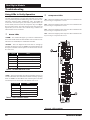
1
Dual Digital Module Troubleshooting LED Diagnostics “PWR” LED: When the Dual Digital Module is powered up, the PWR LED (located below the address switches) should light up and stay on continuously. If it does not light up, check to be sure that the power wiring is connected to the board, the connections are tight, and the VCM-X Modular series controller is powered. If after making all these checks, the PWR LED does not light up, the module is probably defective. Other Checks NOTE: The Dual Digital Module contains no user-serviceable parts. Contact qualified technical personnel if your module is not operating correctly. “COMM” LED: The COMM LED lights up to indicate Communications between the module and the VCM-X Modular series controller. If the COMM LED does not blink, then communications have not been established. Check the connection between the VCM-X Modular Controller, the VCM-X Modular E-BUS Controller, the E-BUS Distribution Module, and the Dual Digital Module. “STAT” LED: As previously described, this LED will blink out the operation mode that the Dual Digital Module is operating under. When the board is first powered up, the STAT LED will do the following: Light up Blink out status code every ten seconds to indicate controller status “ALARM” LED: As previously described, this LED will blink on and off to indicate alarms and diagnostics. Technical Guide 13