1
Table of Contents
OVERVIEW ........................................................................................................................................................ 3
Overview ......................................................................................................................................................................................3
INSTALLATION AND WIRING ........................................................................................................................... 4
Environmental Requirements .......................................................................................................................................................4
Mounting.......................................................................................................................................................................................4
Power Supply and Communications ............................................................................................................................................4
Important Wiring Considerations ..................................................................................................................................................5
VCM-S Modular Controller to Dual Digital Module Wiring ............................................................................................................6
VCM-X Modular E-BUS Controller to Dual Digital Module Wiring ................................................................................................8
START-UP AND COMMISSIONING.................................................................................................................. 10
General.......................................................................................................................................................................................10
Unit Configurations .....................................................................................................................................................................10
SEQUENCE OF OPERATION ........................................................................................................................... 11
Off Mode..................................................................................................................................................................................... 11
Cooling Mode ............................................................................................................................................................................. 11
Dehumidification Mode ............................................................................................................................................................... 11
Heat Pump Heating Mode (Air to Air) ......................................................................................................................................... 11
Defrost Mode .............................................................................................................................................................................. 11
Staging Delays ........................................................................................................................................................................... 11
TROUBLESHOOTING ...................................................................................................................................... 12
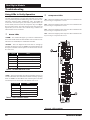
Using LEDs to Verify Operation..................................................................................................................................................12
LED Diagnostics .........................................................................................................................................................................13
Other Checks .............................................................................................................................................................................13
PART NUMBER CROSS REFERENCE TABLE
PART DESCRIPTION
ORION
AAON
COIL
VCM-X Dual Digital Module
OE370-23-DD-C
30311
VCM-X Modular Controller
OE332-23-VCMX-MOD-C
30553
VCM-X Modular E-BUS Controller
OE332-23E-VCMX-C
VCM-X E-BUS Distribution Module
OE365-23-EBD-C
TBA
30312
VCM-X Expansion Module
OE333-23-EM
30308
VCM-X 12 Relay Expansion Module
OE358-23-12R
30309
www.aaon.com
WattMaster Controls Inc.
8500 NW River Park Drive · Parkville , MO 64152
Toll Free Phone: 866-918-1100
PH: (816) 505-1100 · FAX: (816) 505-1101 · E-mail: [email protected]
Visit our web site at www.orioncontrols.com
WattMaster Form : AA-DDM-TGD-01F
Copyright December 2013 WattMaster Controls, Inc.
AAON® is a registered trademark of AAON, Inc., Tulsa, OK.
Neither WattMaster Controls, Inc. nor AAON®
assumes any responsibility for errors or omissions in this document.
This document is subject to change without notice.