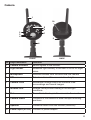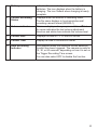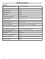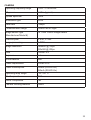
1
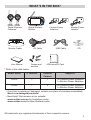
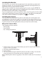
G14xx Series
VIDEO SURVEILLANCE SYSTEM
For more exciting new products please visit our website:
Australia: www.uniden.com.au
New Zealand: www.uniden.co.nz
1
IMPORTANT SAFETY INSTRUCTIONS
This manual contains important information about this product’s operation. If you
are installing this product for others, you must leave this manual or a copy with the
end user.
When using your equipment, always follow basic safety precautions to reduce the
risk of fire, electric shock and injury to persons, including the following:
• This equipment is NOT waterproof. DO NOT expose it to rain or moisture
(for the weatherproof video camera: DO NOT expose it to excessive water or
moisture).
• DO NOT immerse any part of the product in water. Do not use this product near
water, e.g., near a bathtub, wash bowl, kitchen sink or laundry tub, in a wet
basement or near a swimming pool.
• To avoid any risk of electric shock from lightning, avoid handling any electronic
devices (except battery powered ones) during an electrical storm.
• Use only the power cord and/or batteries indicated in this manual. Never dispose
of any batteries in a fire: they may explode. Check with local codes for possible
special disposal instructions.
• Never tug or pull on any power cord: be sure to leave some slack in the cord
when placing your equipment, and always use the plug to unplug cord from the
wall outlet.
• Never leave power cords where they can become crushed, cut, or frayed; when
running power cords, avoid letting them rub against any sharp edges or lie
across any high traffic areas where people might trip over them.
• Do not use the device if the adaptor cords or plugs have been damaged, the unit
has been exposed to liquids, or the unit has been dropped or is damaged.
2
Warning to Parents and Other Users
Failure to follow these warnings and the assembly instructions could result in
serious injury or death. This product is not designed or intended for use as a
medical monitor, nor should this product be used as a substitution for medical or
parental supervision. Always be sure that both the transmitter and receiver are
working properly, and are within range of each other.
STRANGULATION HAZARD. Keep the adapter cords out of the reach of children.
WARNING: KEEP OUT OF THE REACH OF CHILDREN.
Allow for proper ventilation when units are in use. Do not cover the camera or
receiver with any object such as a blanket. Do not place it in a drawer or in any
location which would muffle the sound or interfere with the normal flow of air.
SAVE THESE INSTRUCTIONS!
For best results
To avoid damage to your equipment, follow these simple precautions:
• Do not drop, puncture or disassemble any part of the equipment. There are no
user-serviceable parts inside.
• Do not expose the equipment to high temperatures, and avoid leaving the
equipment in direct sunlight for more than a few minutes. Heat can damage the
case or electrical parts.
• Do not place heavy items on top of the equipment or expose the equipment to
heavy pressure.
• Remove the power adaptor during long periods between usages.
• Clean only with a dry cloth.
Failure to follow the instructions in this operating manual will void the
warranty. Uniden assumes no liability for damages to property or injury to
persons caused by improper handling or failure to comply with these safety
instructions.
3
Contents
WHAT’S IN THE BOX? .........................................................................................5
INSTALLATION ...................................................................................................6
General Placement Considerations ......................................................................................................6
Installing the Monitor ...............................................................................................................................7
Installing the Camera ................................................................................................................................7
BASIC OPERATION ............................................................................................10
Monitor ........................................................................................................................................................10
Camera ........................................................................................................................................................13
LCD Display ................................................................................................................................................14
USING THE G14 SERIES ....................................................................................16
Viewing Modes ........................................................................................................................................ 16
SYSTEM MENUS ................................................................................................18
Alert Menu .................................................................................................................................................18
Power Save Menu ....................................................................................................................................19
System Menu .............................................................................................................................................19
Camera Menu ...........................................................................................................................................22
Record Menu ...........................................................................................................................................23
USING YOUR SYSTEM ......................................................................................27
Recording Video ......................................................................................................................................27
Viewing Recorded Video ..................................................................................................................... 27
Deleting Recorded Files ....................................................................................................................... 28
Viewing on your TV ................................................................................................................................28
Viewing on your Computer ..................................................................................................................28
Remote Viewing Using Skype™ Application .................................................................................. 29
Viewing Recorded Video on Your Computer ................................................................................. 29
Using the Intercom .................................................................................................................................30
Pairing Accessory Cameras ..................................................................................................................30
TROUBLESHOOTING ........................................................................................31
specification ................................................................................................32
ONE-YEAR LIMITED WARRANTY ....................................................................34
4
WHAt’s In tHe BoX?
Digital Wireless
Cameras*
Digital Wireless
Monitor
Monitor Cradle
AV Cable
Screws and
anchors
User Manual
Camera Power
Adaptors*
Monitor Power
Adaptor*
USB Cable
CD
4GB microSD Card
* Refer to the table below.
Model Name
4” Monitor
G1410
1
Outdoor
Camera
1
G1420
1
2
Adaptors
1 x Camera Power Adaptors
1 x Monitor Power Adaptors
2 x Camera Power Adaptors
1 x Monitor Power Adaptors
• If any item is missing or damaged, contact your place of purchase immediately.
Never use damaged products!
• Need help? Get answers at our website:
www.uniden.com.au for Australian model
www.uniden.co.nz for New Zealand model.
All trademarks are registered trademarks of their respective owners.
5
INSTALLATION
General Placement Considerations
• The cameras included with your monitor are weatherproof and have an IP65
weather rating. Water can be sprayed on them and they will still work; however,
the cameras cannot be submerged underwater.
• Although the cameras can be exposed directly to the rain, it is recommended
that, if they are used outdoors, they be mounted under some type of cover like
a patio overhang or eave. As rainwater drops start to dry on the camera glass,
it can create spots that will reflect the light from the infrared LEDs used for night
vision, thus causing lower quality video.
• Also, as dust, grime, and cobwebs accumulate on the camera glass, they can
reflect light from the infrared LED and might lower video quality. Periodically,
clean the lens glass with a soft cloth.
Consider the following when placing the camera:
• Clear line of sight video transmission distance is up to 150ms.
- Walls, especially brick and concrete, shorten the transmission distance.
- Placement next to windows allows better transmission.
• Avoid having a direct light source in view of the camera. This includes street
lights, ceiling or floor lamps, spotlights in the driveway, etc.
• The cameras are equipped with built-in infra-red LEDs so you can use night
vision for 24-hour surveillance. The LEDs automatically activate at night and the
picture viewed turns to black and white. The night viewing range is up to 12ms.
Avoid pointing the camera lens directly at clear glass; the night vision LEDs will
cause a blurred image.
• Optimized motion detection range is up to 12ms. The farther away an object is,
the less accurate the motion detection.
• Avoid pointing the camera directly at any bushes, tree branches, or moving
objects that might naturally move due to winds. Otherwise, the motion detection
feature may record unnecessarily.
• Out of Range displays when the monitor and camera are too far apart.
Reposition the equipment.
• A Low Battery icon displays when you need to recharge the battery.
6
Installing the Monitor
Out of the box, your monitor has enough power to be used when you place and
install the cameras. You can check the camera placement and angle before you
physically screw the camera stands into place.
After you have installed the cameras and set up the monitor, plug the DC 5V AC
adaptor power output cable into the 5V POWER input of the cradle or monitor. Plug
the power plug into a wall outlet or surge protector.
If you are powering the monitor through the cradle, insert the monitor into the cradle
at this point. Press firmly to ensure a good connection. The LED on the side panel
icon displays.
turns red to indicate charging is in progress. The
Installing the Camera
You can mount the camera with the stand on the bottom (for a flat surface such
as a tabletop), on the side (for a wall), or on the top (for the ceiling). When you are
positioning the camera, you might want to bring the monitor along; it’s much easier
to get the camera into the right position when you have the monitor handy.
Mount the Camera Base
The following tools are required:
• Electric Drill
• 5mm Drill Bit
• No. 2 Phillips Screwdriver
1. Hold the base of the camera stand where you want to mount it and mark the
location of the screw holes.
2. Drill holes using the 5mm drill bit.
3. Insert anchors.
4. Use the included screws to attach the base to the wall or ceiling. You can also
screw the base into a flat surface such as a tabletop if needed.
Before attaching the camera, tug gently on the stand to make sure it is securely in
place.
7
Attach the Camera
2
1
Tighten the brace against
the camera to
secure it
in place.
Attach the camera
to the mounting
screw and turn it
to the desired
direction.
3
Loosen the
wingnut to
unlock the
mounting
post.
4
Adjust the post to
the correct angle,
then tighten the
wingnut to lock the
post into place.
1. For each camera, attach the camera bracket to the mounting screw. You can
attach the stand to the top or the bottom of the camera as needed. Tighten it a
few turns, then turn the camera to face the direction you want.
2. Tighten the camera brace up against the camera to secure it into place.
3. Unlock the mounting post by turning the wingnut a few turns to the left.
4. Set the mounting post to the correct angle, then tighten the wingnut until the post
is locked into place.
5. Attach the antenna to the rear of the camera.
8
Power Up the Monitor
1. Press and hold the POWER button on the left side of the monitor for 1 - 2
seconds to turn it on.
2. The monitor displays the Uniden title screen and then displays the live view, if
the paired camera has been powered on. Otherwise Out of Range message
displays.
Power Up the Camera
1. Connect one end of a DC 9V AC adaptor to the camera’s power pigtail and plug
the other end into a 240 volt AC (standard indoor) power outlet.
2. Cameras provided in the kit are already paired to the monitor. Once they are
powered up, the monitor displays images from that camera.
Adjust the camera viewing position, if needed.
If...
there is no camera picture
Try...
Verify that the power supply adaptor for the
camera(s) is plugged in.
the picture quality is poor
Clean the camera lens.
a white image appears at night
The camera’s infra-red LED shines due to the
invisible light that reflects off surfaces such as
glass, causing white light. Place the camera
on the other side of windows with the lens side
flush against the surface to improve the night
vision, or place the camera in a well-lit area.
Night Vision
This camera has built-in IR LEDs, which provides the camera with the ability to view
images in no/low light conditions. It is important to use the provided power adaptor
(and not the batteries) when using the camera for prolonged periods in low light
conditions.
9
BAsIC oPeRAtIon
Monitor
12
1
14
15
11
10
2
13
3
4
9
5
16
6
17
18
19
7
8
No Keys/Indicators
1
Antenna
2
3
LCD Screen
Zoom (+/-)
4
Talk
10
Function
Receives video and audio signals from the
camera.
Displays video from the cameras
Set the image to double size. In Zoom mode,
use the navigation buttons to see the parts of the
image not displayed on the LCD screen.
Return it to original size by selecting Zoom again.
Press and hold while in Live view mode to talk to
the camera side.
5
Navigation Controls
Use the controls in Live view, Menu mode,
Playback mode and Zoom mode.
▼Vol,▲Vol
• Move up or down in Menu mode.
• Increase or decrease the volume in Live view.
• PlayandPauseinPlaybackmode(▲Vol).
• StopinPlaybackmode(▼Vol).
• Move left in Menu mode.
• Press this button to change viewing camera
channel in Live view.
• Fast backward in Playback mode.
• Move right in Menu mode.
• Press this button to change viewing camera
channel in Live view.
• Fast forward in Playback mode.
• Press to access the G14 Series menu.
• Confirm selections in Menu mode.
6
Back
Press this button to return to the previous screen.
7
Video Playback
8
Microphone
During live video, press to go to the Recorded File
screen.
For two-way audio to camera.
9
Power On LED
10
Monitor Stand
On: Battery capacity is good
Flashing: Low battery
Built-in stand for monitor, when not in cradle
11
Speaker
Output sound received from camera
12
Reset Button
Insert a blunt thin object (such as an unbent paper
clip) into the reset button hole on the back of the
monitor.
11
13
Manual Rec
Press this button to start Manual Recording mode.
Press again to stop recording.
14
Power Button
Turns monitor on and off. (Press and hold a few
seconds longer to turn monitor off.)
15
microSD
microSD card slot.
16
USB Port
Uses USB cable to connect the monitor to the
computer for remote access using Skype™.
17
AV Out
Uses AV cable to connect the monitor to the TV to
view live video.
18
LED
(Charging Indication)
19
Power input
(DC 5V)
• Green: Battery is fully charged.
• Orange: Battery is almost charged.
• Red: Battery is charging.
Connect the included 5V DC power adaptor to
power the monitor and/or charge the monitor
battery (when the monitor is not in the cradle).
12
Camera
1
10
5
6
2
3
4
7
9
8
FRONT
No Keys/Indicators
1
Camera Antenna
2
Light sensor
BACK
3
Microphone
Function
Sends signals to the monitor.
Measures light intensity to activate IR LEDs for night
vision.
Receives sounds from the area near the camera
4
PIR sensor
Detects motion within camera’s line of sight.
5
Camera Lens
Mechanism through which the cameras view
surroundings and record images.
6
Infrared LED
7
Pair
Infrared LEDs provide viewing in no/low light
conditions.
Press this button to pair the camera to the monitor.
8
Camera stand
Connects to the camera to allow multiple mounting
positions.
9
Speaker
Transmits sound from the monitor (intercom).
10
Power Input (9V DC) Connect to power adaptor.
13
LCD Display
1
2 3 4 5 6 7
8
Rec 055920-1.AVI
9
10
2013.11.25 06:34:24
11
No Keys/Indicators
1
Signal Indicator
12
13
Function
Shows the camera’s signal strength.
Signal Strength
Perfect
Good
Fair
Low
No Signal
Indicator
2
Channel indicator
3
MicroSD Card
indicator
4
New Record
indicator
5
Overwrite indicator
6
Talk Back
Displays when TALK is pressed
7
Mute
Displays when volume is turned off
14
Warning
None
None
None
None
None
Displays the current channel number. Press or
to switch between available cameras.
Displays if there is a microSD card in the slot.
# A white icon indicates a microSD card has been
inserted. A red icon indicates microSD card
memory is full.
Displays and flashes when a new recorded file is
available.
This indicates that micro SD card will be overwritten
once it is is full.
8
Battery
9
Current Recording
Status
10
Volume indicator
11
Current Date
Indicates the amount of power remaining in the
batteries. The icon displays when the battery is
charging. The icon flickers when charging is nearly
complete.
Displays when the monitor is recording video.
The file name displays in hour/minute/second/
recording camera format (055920-1).
This icon displays when you press ▲Vol or ▼Vol.
An arrow indicates the last volume adjustment
direction and status bars indicate the volume level.
Displays the date in YYYY.MM.DD format.
12
Current Time
Display the time in HH:MM:SS format
13
Auto Recording
Indicator
Icon appears when the camera’s motion detection
function has been triggered. The camera records for
15, 30, or 60 seconds, depending on how it is set on
the Trigger Recording Time screen.
You can also select OFF to disable the function.
15
UsInG tHe G14 seRIes
Viewing Modes
In Live view, video displays live images from the camera in the following modes:
• Quad mode: Monitor displays video from all cameras on a single screen in 4
quadrants.
• Single mode: Monitor displays video from one camera at a time.
• Scan mode: Monitor displays video from one camera at a time, but cycles
through all cameras one by one.
To...
Change between quad view,
single view, and scan for Live
view
Manually start recording
Set up to record automatically
Manually stop/cancel recording
in Manual, Motion, or Schedule
Record mode
Manually cancel a Scheduled
Record
Play back a recording on the G14
Series monitor
Cancel watching a recorded
video
Watch recorded video on PC or
television
16
Do...
From Quad view, press
to cycle the screens
in the following order:
Scan - CH1 - CH2 - CH3 - CH4 - Quad
Press MANUAL REC on top of the monitor
(see page 27).
Refer to Schedule Recording from the Record
menu (see page 26).
Press MANUAL REC on top of the monitor
(see page 27).
Select Record/Schedule Record.
Select the specific day whose recording
schedule you want to cancel.
When that day’s schedule displays, use or
buttons to turn that day’s schedule to Off (see
page 26).
Press
. The Play File screen displays. See
page 27 for details.
Press
On PC: Place the G14 Series microSD card in
the PC’s memory slot (microSD card adaptor
included). You can play the files from the card
itself or copy the files to your computer and
play them from that destination.
On TV: Use the AV cable to connect the
monitor to the TV. Use the monitor’s control
buttons to access the recorded video on your
system’s microSD card.
Set the date and time
See System/Date&Time, page 20.
Transfer a recording from
the monitor’s SD card to the
computer.
Remove the memory card from the monitor
and insert it into an adaptor.
Insert the SD adaptor into your PC.
Select a destination to store the files.
Watch live video on your
smartphone
Be sure both your home computer and
smartphone/device have Skype™ accounts.
Set up your home computer to view live video.
Use Skype™ on your smartphone/device to
call your home computer.
When you are connected, you will see live
video. (See page 29 for details.)
Adjust G14 Series volume
Press▲Vol(increasevolume)or▼Vol
(decrease volume) when viewing a camera.
icon displays, then turns off after 5
The
seconds of inactivity.
17
sYsteM MenUs
Press MENU/OK button on the monitor to access the system menu options.
Use the navigating buttons to navigate up/down/left/right in the menu, and press
MENU/OK to confirm a setting.
The Main menu options are:
• Alert
• Power Save
• System
• Camera
• Record
or
to change options. The icon for the selected option enlarges.
1. Press
2. Press MENU/OK to select that option.
ALeRt MenU
This option allows you to set the alert volume for the unit. There are 6 levels plus
off. [Default = Off (mute)].
The system alerts the user each time the camera detects any motion.
Press
18
or
to increase or decrease the alert volume.
POWER SAVE MENU
This option allows you to enable/disable the Power Save function. Enable this
function to turn off the LCD backlight after 2 minutes of inactivity. The monitor
“wakes up” if it detects motion or if you press any key. (Default = Off)
SYSTEM MENU
These system setup options allow you to configure your system according to your
personal preferences. Use the navigation keys to select one of the six options:
• Date&Time
• Brightness
• A/V out
• Language
• Format
• Default
19
Date & Time
The Month option is automatically selected when you select Date & Time.
1. Press▼Vol,▲Voltoscrollthroughtheoptionsforthatselection.
2. Pressortoswitchtoanothersectionofthedateortime.Press▼Vol,▲Volto
scroll through the options as before.
3. Press MENU/OK to save the current setting and return to the System screen.
# Time displays in “Military” time (i.e., 00-24 hours). For example, 14:30 would be
2:30 PM.
11 30 10 30
Brightness
This option allows you to change the LCD brightness.
There are 6 brightness levels. (Default = 3)
1. Press or to increase/decrease the brightness level (0 - 6).
2. Press MENU/OK to save and return to the System screen.
20
AV Out
This option allows you to select the TV
output format. (Default = PAL)
PAL is the TV standard in Australia.
1. Press ▲Vol or ▼Vol to select either
NTSC or PAL for this option.
2. Press MENU/OK; the System screen
displays.
Language
This option allows you to select the display
language for the system.
(Default = English)
1. Press ▲Vol or ▼Vol to select a
language.
2. Press MENU/OK after you make your
selection. The System screen displays.
Format
This option allows you to format the external storage (microSD) card, deleting all
files on that card. (Default = No)
##Be careful when using this feature. All files on the microSD card will be erased.
1. Insert a microSD card into the monitor.
2. Select Yes, then press MENU/OK.
FORMAT displays; once formatting is complete, the System screen displays.
##If you try to format the microSD
card but no microSD card is
inserted, NO SD CARD displays.
21
Default
This option allows you to restore the G14 Series to factory settings. (Default = No)
Camera pairings and date/time settings are not affected by a reset.
1. Press ▲Vol or ▼Vol to select either No or Yes for this option.
2. Press MENU/OK after you make your selection. The System screen displays.
CAMERA MENU
This options allows you to pair the monitor
with up to 4 cameras or turn on/off
individual channels (cameras).
Press ▲Vol or ▼Vol to select Pair or On/
Off for this option.
The two cameras that come with your
system are paired to the monitor at the
factory.
Pair
22
Select this option if you are pairing
accessory cameras or changing a camera’s
channel assignment.
1. Press ▲Vol or ▼Vol to select the
camera you want to pair to the monitor.
2. Press MENU/OK.
An information message displays,
indicating that you have 30 seconds to
press the pairing button on the camera.
The video displays on the monitor when
that camera has been paired.
On/Off
This option allows you to turn on or off an individual channel. The camera will
remain powered on but the monitor will no longer receive video and audio.
1. Press▲Volor▼Voltoselectthechannelwhosestatusyouwanttochange.
2. Press or to change the setting (On or Off).
3. Press MENU/OK to confirm the setting. The main Camera screen displays.
ReCoRD MenU
The Record screen contains 5 sub-screens that help you establish the quality level
of your recordings and a repeatable one week recording schedule.
• Video Quality
• Trigger Recording Time
• Motion Sensitivity
• Schedule Recording
• Overwrite
23
Video Quality
This option allows you to preset the output
video quality for the unit.
(Default = Low 320 × 240)
1. Press ▲Vol or ▼Vol to choose between
higher quality (High 640x480) and lower
quality (Low 320x240) video output.
2. Press MENU/OK. The Record screen
displays.
Trigger Recording Time
Various things can alert the system to start recording. These triggers range from
the wind blowing a tree branch into tan outside camera’s line of sight to someone
walking into a room. This option lets you set the duration the system will record
once it has been triggered. (Default = 30 s)
1. Press ▲Vol or ▼Vol to select the recording time.
2. Press MENU/OK.
If you select Off, the system won’t record, even if a trigger occurs and the motion
sensitivity is set to High. If you select a recording duration (15, 30, or 60 seconds),
displays during recording.
3. The Record screen displays.
24
Motion Sensitivity
This option allows you to set the motion sensitivity for each channel individually. For
example, if Camera 1 is an outside camera, you could set the sensitivity lower. This
could stop the cameras from detecting small movements, such as the wind moving
a tree branch. (Default = Low)
1. Press ▲Vol or ▼Vol to select the channel whose sensitivity you want to adjust
and press MENU/OK.
2. The camera’s sensitivity levels display on the next screen. Select the sensitivity
level and press MENU/OK.
The Motion Sensitivity screen displays again.
25
Schedule Recording
This option allows you to create a weekly recording schedule. This weeky schedule
repeats until you change it. You can set each day separately, and you can also
set that day’s schedule to turn on or off. For example, if you have camera 1 set to
record your backyard every evening from 20:00 hours (8:00 PM) until 23:00 hours
(11:00 PM) but you will be having a party in the backyard that evening, you can turn
off that day’s scheduled recording. (Default = Monday / Start Recording Time:00:00
/ End Recording Time: 00:00 /Off)
1. From the Record screen, select Schedule Recording and press MENU/OK. The
Schedule Recording screen displays. Select a day and press MENU/OK. The
start and end time setting screen for that day displays.
2. Using▲Volor▼Vol,scrolltosettherecordingstartandendtimes.Press
after each selection to move to the next. For example, set Start Recording Time Hours, then press to move to Start Record Time - Minutes.
3. Set the End Recording Time in the same way and then press or to select On
or Off.
4. Press MENU/OK to set your selection. The Schedule Recording screen displays.
Overwrite
When the microSD card is full, the new video recording overwrites the oldest video
recording. Select Yes to enable this function. (Default = No)
26
UsInG YoUR sYsteM
ReCoRDInG VIDeo
Video records on the 4GB microSD card included in your package (the G14 Series
will support up to a 32GB microSD card). When the receiver records (motion,
schedule, manual, etc) all the buttons are disabled except MANUAL REC. The
system responds normally after the recording has ended.
You can set up schedule recording (page 26), record when motion is detected (page
24) or manually record by pressing the MANUAL REC button.
To stop recording and continue with normal operations, press MANUAL REC.
Manual Recording
# Be sure a microSD card is inserted into the microSD card slot.
1. Press MANUAL REC on the top of the monitor. The monitor records in 10 minute
blocks.
2. Press MANUAL REC again to cancel manual recording.
3. In Recording mode, only the TALK button and sound are active.
4. When there is new recorded file,
(yellow) flashes on the LCD screen. When
the microSD card is full,
(red) flashes.
Viewing Recorded Video
1. Press
to enter the Play File screen.
2. Select the Video folder and press MENU/OK.
The Video folder contains other folders sorted by date (Format = YYYYMMDD).
For example: 20131212 means the videos in this folder were recorded on 12th
December,2013.Press▲Volor▼Voltoselectafolderyouwanttoviewand
press MENU/OK to open that folder and browse the files inside.
Inside that folder are record files, sorted by time.
For example: 123030_1 means the video is recorded at 12:30:30 and from
camera 1.
3. Select the video you want to view and press MENU/OK. The video plays on the
LCD screen.
• Use the navigation buttons to manage the video:
▲Vol-Pause,playvideo
▼Vol-Stop
•
Forward (up to x16 speed)
•
Backward (up to x16 speed)
•
Exit the video
•
After you exit the video, exits Playback function
27
Deleting Recorded files
You can delete a specific recorded video file or an entire folder of files. A red “X”
displays to the right of the folders and recorded video files on the Play File screen.
1. Press to highlight the red “X” beside the folder or file you want to delete and
then press MENU/OK.
2. A confirmation screen displays. Use or to select Yes or No, and then press
MENU/OK to confirm the selection.
Viewing on your tV
1. Connect the monitor to your television using the AV Output cable (included).
2. The monitor screen goes blank and the TV screen displays the camera output.
# The monitor controls still operate while the system is connected to the TV. You
can change cameras, set the cameras to scan through each in sequence, etc.
Viewing on your Computer
You can also view the Live video from the G14 Series system on your computer.
The Live screen displays on the PC via Skype™.
Before installing the hardware, ensure that you:
• have connected the monitor to your PC using the included USB cable.
• set up a Skype™ account linked to your G14 Series.
(please refer to www.skype.com for details on setting up this free account)
Install the ‘Wireless Monitoring System’ hardware according to the instructions
given below.
1. Insert the CD included in your package into your PC.
For Windows: Select the USB Driver file and double-click to run the program.
For MAC: Double-click on the .MAC driver to release the ZIP file. Locate the
PKG file and double-click to run the program.
2. For Windows: Follow the instructions from the Install Wizard. Select Finish to
complete the installation. Found New Hardware displays.
For MAC: Follow the instructions on the screens. Select Close to complete
installation. An Installation Successful screen displays.
3. Next, login to your Skype™ account and navigate to the option Video Settings.
# Ensure that the ‘Wireless Monitoring System’ is selected under webcam
options.
28
REMOTE VIEWING USING SKYPE™ APPLICATION
To set up remote viewing via Skype™, first follow the procedures to view on your
computer (page 28).
##Be sure that the Skype™ account that is linked to the G14 Series is set to “Auto
Answer” mode.
Setup your wireless device or remote computer
1. Set up another Skype™ account (let’s call it the second Skype™ account) on your
wireless device or remote computer.
2. Invite the other Skype™ account (i.e., the first account, the one linked to the G14
Series) into your contact list.
3. Log into your first Skype™ account, and accept the invitation from the second
Skype™ account.
##You must have a separate Skype™ account to call the home computer. You
cannot use your home computer’s Skype™ account to call itself.
Viewing from your wireless device or remote computer
1. After connecting the monitor to the PC with the included USB cable, select the
camera you want to set up for remote viewing.
##For MAC system: you must connect the monitor to the home computer before
activating Skype, otherwise Skype cannot find the monitor.
2. Activate Skype™ on the PC and log into your first Skype™ account and ensure
that the Live screen displays.
3. From your wireless device or remote computer, log on to your second Skype™
account call the first Skype™ account. Since your first Skype™ account has been
set up to Auto Answer, you should be able view the live video from the camera
you set up in Step 1, on your wireless device or remote computer.
Viewing Recorded Video on Your Computer
The files that record on the G14 Series record onto the micro SD card in AVI format.
You can take that card and play it on your computer. You will need:
• G14 Seriers microSD card
• MicroSD card adapter for laptop (included) or SD card reader for other systems
(not included)
1. Remove microSD card from the unit. Place it in the adaptor and insert adaptor
into your PC.
2. Navigate to the SD card on your system.
3. Select the files you want to view and click Open.
4. The files begin playing, in order, through your default media player.
29
Using the Intercom
The Intercom feature lets you talk to whomever is within camera range.
1. Make the camera you want to establish an intercom link with the full screen live
view camera.
2. Press and hold
on the monitor.
3. Speak clearly into the microphone.
4. Release
to listen to the response.
Pairing Accessory Cameras
The two cameras that come with your G14 Series are paired to your monitor at the
factory. If you add cameras, install them and then pair the camera to the monitor.
1. Press MENU/OK to bring up the System Menu screen.
2. Select the Camera option.
3. Select Pair and then press MENU/OK. The Pair screen displays. The pairing
function assigns each camera to a different channel on the wireless monitor (up
to 4 cameras), and is necessary for configuring additional cameras.
4. Select the channel you want to pair the camera to and press MENU/OK. The
Press Pair Key message screen displays.
5. Within 30 seconds, press the Pair button located on the camera. Once the
camera pairs to the monitor, you can view the camera transmissions on the
monitor.
30
TROUBLESHOOTING
Problem
No picture
The picture keeps dropping
No sound
Loud, screeching noises
(Audio feedback)
The picture is choppy
The picture appears grainy
(using AV Out to view on
TV/Monitor)
Recording problems
The monitor picture has
frozen
Solution
• Check all camera connections.
• Verify that the AC adaptor is plugged in.
• Make sure the monitor is ON.
• Make sure the camera is in range.
• Move the camera closer to the monitor.
• Reposition the camera, monitor, or both to
improve reception.
• Increase the volume.
• Make sure there is sound within range of the
camera’s microphones.
Move the camera and the monitor farther apart.
• Move the camera and monitor closer to each
other.
• Remove any obstructions between the
camera and monitor.
• View files on a smaller TV/PC monitor.
• Try viewing through your TV’s Picture-InPicture function, if available.
• Make sure the microSD card is inserted
correctly.
• Check that the microSD card memory is not
full.
• Verify that the microSD card is compatible
with the G14 Series. It can support up to
32GB microSD card.
Interference or a low battery may have caused
the picture to freeze. Use a blunt object like an
unbent paper clip to press RESET to reset the
monitor. This will also turn off the monitor. Press
the POWER button to turn it on.
31
specification
MONITOR
Operating frequency range
2.400 ~ 2.4835GHz
RX sensitivity
– 81dBm
Spread spectrum
FHSS
Modulation type
GFSK
Data Rate
2 Mbps
Communication range
150ms Line of Sight
Display size/type
4.3” TFT LCD
Resolution H:
480; V: 272
Power requirement
5.0V DC ± 5%
Power consumption
350mA (Normal) 900mA (Charging)
Operating temperature range
– 10 ~ 40˚ C
Operating humidity range
Within 85% Relative Humidity
RoHS Compliance
Yes
Battery life
4.5 hours
Private ID for connection
Yes
Recording storage
4GB microSD card (included). Supports up to
32GB
Plastic
Housing material
32
CAMERA
Operating frequency range
2.400 ~ 2.4835GHz
TX power
15dBm (typical)
Spread spectrum
FHSS
Modulation type
GFSK
Data Rate
2 Mbps
Communication range
150ms Line of Sight
Image sensor type
(Manufacturer/Model #)
1/4” color CMOS image sensor
Effective pixel
H: 640; V: 480
Image processing
MJPEG
Image resolution
Lens
640x480 @ 10fps
320x240 @ 20fps
3.6mm F2.0
Exposure
Auto
White balance
Auto
Power requirement
9.0Vdc ± 5%
Power consumption
Operating temp range
160mA (IR LED Off)
350mA (IR LED On)
–10 ~ 50° C
Weatherproof
IP65
RoHS Compliance
Yes
Camera Housing Material
Plastic
33
ONE-YEAR LIMITED WARRANTY
G14 Series
IMPORTANT Satisfactory evidence of the original purchase is required for
warranty service.Please refer to our Uniden website for any details or warranty
durations offered in addition to those contained below.
Warrantor
The warrantor is either Uniden Australia Pty Limited ABN 58 001 865 498
(“Uniden Aust”) or Uniden New Zealand Limited (“Uniden NZ”) as the case may be.
Terms of Warranty
Uniden Aust/NZ warrants to the original retail purchaser only that the G14 Series (“the
Product”), will be free from defects in materials and craftsmanship for the duration of
the warranty period, subject to the limitations and exclusions set out below.
Warranty Period
This warranty to the original retail purchaser is only valid in the original country of
purchase for a Product first purchased either in Australia or New Zealand and will
expire one (1) year from the date of the original retail sale.
If a warranty claim is made, this warranty will not apply if the Product is found by
Uniden to be:
(A)Damaged or not maintained in a reasonable manner or as recommended in the
relevant Uniden Owner’s Manual;
(B)Modified, altered or used as part of any conversion kits, subassemblies or any
configurations not sold by Uniden Aust or Uniden NZ;
(C)Improperly installed contrary to instructions contained in the relevant Owner’s
Manual
(D)Repaired by someone other than an authorized Uniden Repair Agent in relation to
a defect or malfunction covered by this warranty; or
(E)Used in conjunction with any equipment, parts or a system not manufactured by
Uniden.
Parts Covered
This warranty covers the Product and included accessories.
User-generated Data
This warranty does not cover any claimed loss of or damage to user-generated data
(including but without limitation phone numbers, addresses and images) that may be
stored on your Product.
34
Statement of Remedy
If the Product is found not to conform to this warranty as stated above, the Warrantor,
at its discretion, will either repair the defect or replace the Product without any charge
for parts or service. This warranty does not include any reimbursement or payment of
any consequential damages claimed to arise from a Product’s failure to comply with
the warranty.
Our goods come with guarantees that cannot be excluded under the Australian
Consumer Law. You are entitled to a replacement or refund for a major failure and
for compensation for any other reasonably foreseeable loss or damage. You are also
entitled to have the goods repaired or replaced if the goods fail to be of acceptable
quality and the failure does not amount to a major failure.
This warranty is in addition to and sits alongside your rights under either the
COMPETITION AND CONSUMER ACT 2010 (Australia) or the CONSUMER
GUARANTEES ACT (New Zealand) as the case may be, none of which can be
excluded.
Procedure for Obtaining Warranty Service
Depending on the country in which the Product was first purchased, if you believe
that your Product does not conform with this warranty, you should deliver the Product,
together with satisfactory evidence of your original purchase (such as a legible copy
of the sales docket) to Uniden at the addresses shown below. You should contact
Uniden regarding any compensation that may be payable for your expenses incurred
in making a warranty claim. Prior to delivery, we recommend that you make a backup
copy of any phone numbers, images or other data stored on your Product, in case it
is lost or damaged during warranty service.
UNIDEN AUSTRALIA PTY LTD
Service Division
345 Princes Highway,
Rockdale, NSW 2216
Phone number: 1300 366 895
Email address: [email protected]
UNIDEN NEW ZEALAND LTD
Service Division
150 Harris Road, East Tamaki
Auckland 2013
Phone number: (09) 273 8377
Email address: [email protected]
35
©2013 Uniden Australia Pty Ltd/Uniden New Zealand Limited
Printed in PRC
36