1
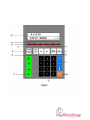
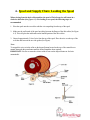
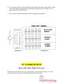
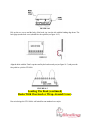
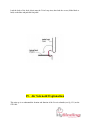
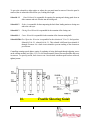
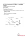
GBC STL1000
Wire Binder
Instruction Manual
Provided By
http://www.MyBinding.com
http://www.MyBindingBlog.com
GENERAL
CORPORATION
AUTOMATED
DIVISION
BINDING
FINISHING
STL-1000 SEMI-AUTOMATIC TWIN
LOOP BINDER
60 Hz. SERVICE MANUAL REV 1.0
Section:
pg.
Table of contents………………………………..………………………..……..…..…1
1. Installation and setup preparation………………..…………..…………..…2
2. About this Manual……………….………………………………………………,,,,4
3. Specifications…………………………………………………………………......5
4. Theory of Operations…………………………………………………………….8
5. Operating instructions for keypad……………………..……………….……11
6. Spool and Supply Chute Loading the Spool……………………………….14
7. Spool and Supply Chute Adjusting the Supply Chute………………...…16
8. Feed and cut Feed Wheel Guide Adjustment…………………………..….17
9. Feed and Cut Height and Width Adjustment of Guides……………..…..18
10. Loading Area…………………………………………………………………..…19
11. Book Transport Area……………………………………………………….…..20
12. Closing Area…………………………………………………………………...…21
13. Closing Height Adjustment……………………………………….……….…..23
14. Loading the Book…………………………………………………..………...…24
15. Air Solenoid Explanation……………………………………….…………..…26
16 Troubleshooting Guide…………………………………………..……….……27
17. Maintenance Requirements…………………………………….……….……33
18 Exploded Assembly and Parts List………………………………….….…..36
1
19
20.
21.
22
Exploded Assembly and parts list conveyor………………..……….……63
STL- 1000 Field Problem Report Form……………………………..……… 69
Electrical Diagram………………………………………………………………70
Electrical Parts Layout…………………………………………………..….…72
NOTES………………………………………………………………………….…75
FOR YOUR SAFETY
“
o
“ means dereel
Marty Moore
Your safety as well as the safety of others is
important to us at GBC. In this Service Manual and on
the STL1000 itself are important safety messages.
Please read these message carefully.
The Safety Alert symbol precedes each
safety message in this manual. This symbol
indicates a potential safety hazard that
could injure you or others, as well as cause
product or property damage.
This safety message means that you could be
seriously hurt or killed if you open the electrical
enclosure and expose yourself to hazardous voltage:
Do not connect electrical power to the STL1000 or
attempt to operate it before reading this Operators
Manual or you have been fully trained as an operator.
Save the operator’s manual for future
use and referral.
Keep hands, long hair, neckties, and loose
articles away from moving parts.
Never override or attempt to defeat electrical or
mechanical interlock devices
Never insert objects or spill liquids into the
STL1000. They may contact dangerous voltage
or short out components, resulting in fire or
dangerous shock.
This safety message means that your hands could be
crushed and cut if you place your hands in the area of
moving parts:
Connect the STL1000 only to the electrical
supply shown in the machine specification
section of this manual and the Serial/Rating label
on the equipment. Connect to a power outlet
installed near the equipment and easily
accessible.
Connect the plug only to a matching receptacle,
contact a qualified electrician to have one
installed.
The following ISO and IEC symbols appear on this
product.. Their meaning is:
“I” means Power On
“O” means Power Off
“ ! “ means emergency stop
Turn the STL1000 power “Off” (O) at the end of
each day.
Do not attempt to service the STL1000. Contact
an authorized GBC service representative if any
of the conditions listed below are encountered:
2
?? Liquid has been spilled into the STL1000 has
been exposed to rain or water.
?? STL1000.
?? The STL1000 has been dropped, bumped, or
dented.
?? The product does not operate normally when
following the operating instructions.
WARNING:
SUPERVISORS PLEASE NOTE:
THESE PRECAUTIONS MUST BE FOLLOWED
WHEN OPERATING OR SERVICING THIS MACHINE.
?? ALL OPERATORS MUST BE PROPERLY TRAINED
PRIOR TO USING THIS EQUIPMENT.
?? READ INSTRUCTION MANUAL BEFORE OPERATING
OR SERVICING THIS MACHINCE.
?? ONLY A TRAINED, QUALIFIED TECHNICIAN SHOULD
SERVICE THIS MACHINE.
?? DO NOT ATTEMPT SET-UP CHANGES UNLESS
FULLY TRAINED.
?? FOLLOW ALL STATE, LOCAL AND FEDERAL POWER
LOCKOUT / TAGOUT STANDARDS WHEN SERVICING
THIS EQUPIMENT.
?? HAVING MACHINE UNDER POWER WHILE MAKING
ALTERATIONS CAN RESULT IN SERIOUS BODILY INJURY.
ALWAYS DISCONNECT ELECTRICAL POWER AND AIR
SUPPLY BEFORE MAKING ALTERATIONS.
?? NEVER OPERATE MACHINE WITHOUT ALL GUARDS
IN OPERATING POSITION.
?? SAFETY GLASSES SHOULD BE WORN AT ALL TIMES WHEN
OPERATING THIS MACHINE OR MANUALLY CLIPPING WIRE.
3
.
KEEP HANDS AND LOOSE CLOTHING AWAY FROM ALL MOVING PARTS.
1.
Installation and setup Preparation
Use this section to properly unpack ,set into place, and setup the STL1000.
1.1 Inspect the shipping container for any visible damage while the trucking company is still
there . If you see any damage, file a damage claim with that trucking company immediately .
Otherwise you may be responsible for any needed repairs.
1.2 Remove the cardboard slip cover and dispose of in accordance with local
regulations.
1.3 Cut the banding material securing the output conveyor to the shipping skid. Remove
conveyor from shipping skid and move to the location where the STL1000 is to be located
in your facility .
1.4 There are four bolts securing the STL1000 to the shipping skid (REF. FIG. 1A). These
bolts are located one in each foot pad of the STL1000. Use a ¼” Allen wrench to remove
these bolts and discard.
1.5 Locate the orange colored foot pedal secured to the shipping skid. Remove the fasteners
that secure the foot pedal to the skid and discard fasteners. Place foot pedal on the table
top of the STL1000 .
CAUTION: Make sure the foot pedal will not fall off the table
top. It may damaged by falling.
1.6 Refer to fig._1A_ for fork lift points of the STL1000. Using a fork lift with a lift capacity of
700kg/2000lbs. , lift the STL1000 from the shipping skid and transport it to the operating
location.
1.7 Have your electrician hook up the appropriate power requirements. Refer to section 3 of
this manual to find the right requirements for your machine
CAUTION DO NOT
APPLY POWER TO THE STL1000 !! A GBC technician will check to insure proper
power is present when installation is scheduled . YOU WILL VOID YOUR
WARRANTY IF YOU APPLY POWER.
1.8 You will need to supply compressed air to the STL1000. Refer to section 3 of this manual
for minimum air requirements . A quick connect is supplied on the air regulator located on
the rear of the machine..
1.9 Be sure that you have TWIN LOOP WIRE and enough prepunched books to run your
machine for at least one hour . Please contact your sales representative if you have any
supply needs.
1.10 Contact GBC National service to schedule a technician to complete your installation.
4
5
6
2.
About this Manual
2.1
General
REV. 1
This manual is intended as a training and reference document for persons
responsible for installation, service and maintenance of the STL-1000 binder. It is
assumed the reader has basic mechanical and electrical troubleshooting abilities.
This Service Manual, revision ( A ), covers 220 Volt, 3 Phase, 60 Hz STL-1000,
version _1 system.
2.2
Document Control
It is intended that future revisions of this document will be published, please refer
to the revision number on the top of this page to determine the most recent.
2.3
Problem Solving
The path for solving problems with the STL-1000 should proceed in the following
sequence:
1)
Find the description of the problem in the table in section 16
2)
Evaluate the list of possible causes for the probable one.
3)
Proceed to the referenced section (see 4 ) for further diagnosis. Part
replacement instructions (section 18 or 19) or adjustment instructions
(section 6 thru 14 ).
4)
If problem is not properly described in the problem column of the
troubleshooting tables of section 16, reread the Theory of Operation
(section 4 ) for insight.
5)
If the problem is unsolved call for support with a clear description of the
problem and the results of any unsuccessful solution you have tried.
6)
Fill out and Fax the Problem Report Form (section 20 ) after solving
the problem. A strong feedback loop from service personnel is the best
way to improve the design and manufacturing of our products.
7
3.
Specifications
Use this section to determine proper installation requirements as well as the capabilities
of the STL-1000.
3.1
Purpose
The STL-1000 is designed to automatically supply spool fed Twin Loop elements cut to a
specified length and is automatically staged for the next book to be bound.
Operator hung pre-punched documents are transported to the closing area, bound and are
transported from the bind area to a stacking conveyor.
3.1.1
Dimensions
Machine only: 85” L x 56” W x 50” H (2.16M x 1.42M x 1.27M ).
Smallest doorway machine will fit through 40” (1.016M) wide (with the removal of the
spool holder assembly). NOTE: This unit should only be removed by a GBC service
tech.
Recommended work area: 10 ft. x 10 ft. (3.05M x 3.05M).
Shipping: 65” x 91” x 60” high (1.65M x 2.31M x 1.52M).
3.2.2
Weight
Weight (machine only): 1200 lbs. (545.6Kgms.)
Shipping weight: 1350 lbs. (613.6Kgms.)
3.3
Electrical Power
2.3.1 Voltage
220 VAC, 60Hz
2.3.2 PHASE
3
2.3.3 Current 2.3.3 Short circuit interrupt
15 amps
capacity: 2000 A
8
3.4
Compressed Air
8 cfm at 80 psi ( 227L/min @ 522K Pa )
3.5
Environment
Ambient air temperatures, 41 degrees F to 104 degrees F. ( 5 degrees C to 40
degrees C.)
Altitude rating, up to 3280 feet ( 1000 meters ).
3.6
Noise Generation
TBD
3.7
Initial Year of Manufacturing:
3.8
Productivity
1999
3.8.1 Cycle Time
The time the system takes to bind a placed document until it is ready to accept the
next document, independent of the operator, is dependent on the specified length
of the Twin Loop element.
The STL-1000 is capable of up to 1,000 books per hour.
3.8.2
Throughput
The number of documents produced in a given time period depends on element
length, document punching quality, but most importantly operator proficiency.
3.9
Book Thickness
3.9.1
9
The STL-1000 can successfully bind documents within the capacity of each given
Twin Loop element size. Use the element size chart supplied by your Twin Loop sales
representative to determine the appropriate element for the book to be bound. If book
size is at the maximum for a given size use the next larger size to insure quality closure of
the bound book.
3.9.2
Bind Length
The STL-1000 is capable of a book bind length of a minimum of 3 inches (76mm ) and
with a maximum of 13 inches (330.2mm ).
3.9.3
Book Width
The STL-1000 is capable of transporting books with the unbound edge width of 3 ½’
(85.75mm )to 12’ (304.2mm ).
3.9.4
Hole Quality
The holes must be pre-punched in the paper and be of 2 to 1 or 3 to 1 punch pattern.
The quality of the holes has a direct relationship on the success of the operators ability to load
books on to waiting Twin Loop elements. Cleaner , crisp holes that align well from
one page to the next will speed up the process of loading books on to the STL-1000.
10
4. Theory of Operation of the STL-1000
Conditions at Power up of the STL-1000
1.
2.
Closing guard must be closed to actuate the closing guard interlock switch IS-1. IS-1 has
two switches in one housing.
A.
One side of the IS-1 breaks main power to the E-stop.
B.
The other side of IS-1 is used to monitor 24 volts to the P.L.C. at X7
Which shouldn’t be illuminated.
P.L.C. is in ready condition should have at least X0, X13 and Y12, or Y13.
Conditions After Power up of the STL-1000
1.
2.
Series of events after the depression of the foot switch (FS).
A.
X6 on the P.L.C. will illuminate.
B.
Y2 to energize Sol-2 (pusher) to advance book to closing area.
C.
Y6 to energize 1CR to turn on 1M (feed motor) to feed element to be cut.
D.
Y10 to energize 3CR to turn on 3M (belt) to advance element is cut.
During element feed cycle:
A.
Either the signal from X4 (count prox 2:1) or X10 (count prox. 3:1) will be used
to count the number of element legs to the number entered into the keypad.
11
B.
Once the entered number is reached Y6 (feed 1M) is turned off.
C.
Y4 energized Sol-4 (cut) which charges the air cylinder to swing the knife and
drop the pawl into the element stop gear to stop rotation of the element feed shaft.
At this point the feed shaft should be stopped so the knife can cut a stationary
element. Through P.L.C. timer Sol-4 is deenergized through Y4 to release the
knife and pawl.
Conditions After Power up of the STL-1000 (Continued)
3.
Series of events during the book transport and closing cycle:
A.
After pusher has advanced LS-2 (forward 1) will close and illuminate X1 on the
P.L.C.
B.
Y5 will energize Sol 1 (door) closing doors on the closing area guard. This will
also open IS-2 at X13 and close IS-2 at Y3. (NOTE: IS-2 has two sets of
switches in one housing).
C.
Y3 energizes to fire Sol-3, which charges the closing air cylinder to actuate the
closing ram to full down stroke.
D.
When the ram reaches its full down stroke LS-3 (close) actuates and illuminates
X2 on the P.L.C. and releases Sol-3 through Y3 to let the ram return to its home
position. NOTE: Home position is fully up.
E.
Sol-1 is deenergized through Y5, which opens the guard doors.
F.
Sol-2 is deenergized through Y2. The pusher returns home and actuates LS-1,
which illuminates X0 on the P.L.C.
G.
Y11 energized 4CR (conveyor 4M) to advance conveyor to a predetermined
distance through an entry from the keypad.
Conditions on a Need Basis
1.
Dereel Unit
12
A.
When dereel switch is on auto, spool prox X3 illuminates when no element is
present Y7 illuminates to fire 2CR which turns on 2M (dereel).
B.
2.
When dereel switch is on manually pressing the green button will illuminate X15
then Y7 on the P.L.C. to turn on 2CR (dereel) which turns on 2M.
Pitch Selection
A.
When pressing 2:1 on the keypad Y12 on the P.L.C. will illuminate and fire Sol-5
to change the air cylinder to shift the feed sprocket. At this time X4 on the P.L.C.
is being used to count 2:1 by prox switch.
Conditions on a Need Basis (Continued)
B.
When pressing 3:1 on the keypad Y13 will illuminate on the P.L.C. and fire Sol-6
to charge the air cylinder to shift the feed sprocket. At this time X10 is being used
to count 3:1 by prox switch.
13
5.
STL-1000 OPERATING INSTRUCTIONS FOR KEYPAD
MAIN MENU
When you first power up the machine you should see the following two lines on the Keypad.
B.COUNTER
SETUP MENU
0
0
( any number may appear)
Line 1: “B. COUNTER:” = Batch Counter. This counter will count the number of books, which are
bound on the STL1000 and display a running total.
To reset this counter, use the ? arrow key to move the cursor over. When blinking, key in “0” from the
numeric section of the keypad then press “ENTERS”. The value “0” will be displayed.
Line 2: SETUP MENU:” The Setup Menu will allow you to make other adjustments to control the
STL1000. Use the ? arrow key to move the cursor over to the ? arrow. Press the “ENTER” key to
get into the Setup menu.
Line 3: “ SERVICE MENU:” The Service Menu will allow our service Technicians to monitor the
STL1000 when making service calls. There is no useful information in this menu for the operator or
setup person. You can get into the Service Menu in the same manner as the Setup Menu.
SETUP MENU
Line 1: “NO. OF LOOPS:”= Number of Loops required to bind your book.
14
Use the numeric keypad to key in the number of desired loops and press “Enter”.
The range of amount of loops is limited from five (5) through forty-two (42).
Line 2: “CONVEYOR STEP:” = The amount of travel desired on the Output conveyor. Use the
numeric keypad to key in the amount of desired travel and press “ ENTER”. The range of travel is
limited to one (1) through six (6) inches.
Line 3: “GOTO MAIN MENU:” = This will bring you back to the Main Menu so the operator can
view the batch count as they run the STL1000.
Press the “ENTER” key to return to the main menu.
Line 4: “SERVICE MENU:” = The Service Menu will allow our Service Technicians to monitor the
STL1000 when making service calls. There is no useful information in this menu for the operator or
setup person. You can get into the Service Menu in the same manner as the Setup Menu.
FUNCTION KEYS
(fig. 1 Section 5)
There are six “Function Keys” on the keypad, which will allow you to activate certain functions of the
STL1000 during the setup process.
PUSHER ADVANCE / HOME: This key will allow you to transport a prehung book into the closing
area or to discharge a bound book onto the conveyor. Press this key again to return the Pushers back
to the home position. NOTE: A red light will illuminate above the PUSHER key and the message
“AUTOMATIC CYCLE IS NOT READY!!! “ will appear on the display on the keypad Make sure
the pushers are in the home position and the display doesn’t read “AUTOMATIC CYCLE IS NOT
READY “ to run in automatic mode.
RAM DOWN / UP: This key will allow you close the element of the book in the closing area. Press
this key again to return the Ram to the up position.
NOTE: A red light will illuminate above the RAM DOWN / UP key, also the message “
AUTOMATIC CYCLE IS NOT READY “ will appear on the display on the keypad when the RAM
is in the down position.
3:1 This key will shift a gear in the feed area so you can run with 3:1 pitch elements.
2:1 This key will shift a gear in the feed area so you can run with 2:1 pitch elements.
FEED ELEMENT: This key will feed and cut an element to the desired length.
CUT ELEMENT: This key will cycle the cut unit, can be used to test knife block height setting or if an
element didn’t cut in the auto cycle mode.
15
16
17
6. Spool and Supply Chute Loading the Spool
When viewing from the back of the machine, the spool of Twin Loop wire will rotate in a
clockwise direction (See figure 6-1). For loading a new spool, the following steps are
recommended:
1. Place the spool onto the two rollers with the wire unspooling from the top of the spool.
2. Make sure the end boards of the spool are riding between the flanges of the idler roller (See Figure
6-2). This will place the end boards on the knurled portion of the drive rollers.
3. Unspool approximately 5 feet of wire from the top of the spool. Place the wire over the top of the
cross bar and between the two side guides (See Figure).
Note:
To unspool the wire, twist the collar on the despool button located on the top of the control box to
manual, then push the green button until the desired length has been acquired.
IMPORTANT: Be sure to return the selector collar to auto on the despool button to feed wire
automatically.
18
SPOOL AND SUPPLY CHUTE LOADING THE SPOOL
(CONTINUED)
4. Lay the wire inside the storage chute and thread the scrap paper between both drive rollers and
wind it up on the scrap take-up spool in a counter-clockwise direction (See Figure 6-3).
Notes:
1. The scrap paper should be wound taunt to prevent it from breaking when the spool drive starts up.
2. The storage chute has a sensor at the bottom to control the spool drive. The sensor will start and
stop the spool drive on demand to replenish the supply of wire to the storage chute.
19
7. Spool and Supply Chute Adjusting the Supply Chute
The supply chute is designed to be used in three different positions (see figure 7-1). The upper position
is for larger size wire -1” and 1 ¼”. The middle position is for medium sizes 9/16” through 7/8’. The
lower position is for the small size wire - ¼” through ½”. The smaller sizes need more weight inside the
supply chute to prevent the wire from unspooling on the bottom side of the spool. On the other hand,
the larger and medium sizes will stretch too much, causing misfeeds in the feed area if left in the lower
position.
For the Small and Medium Sizes:
1. Loosen the handle and slide the storage chute to the required position.
2. Tighten the handle to secure the storage chute.
For the Larger Sizes:
1. Remove the right and left -hand supply chute brackets and replace them with brackets
#4270035 and #4270036, which are, include with the machine.
2. Fasten the right hand bracket to the upper mounting hole (see figure 7-1).
3. On the left side, swing the supply chute adjustment bracket over and fasten the left bracket as
shown in figure 7-1.
20
8. Feed and Cut Feed Wheel Guide Adjustment
The outboard guide on the feed wheel (see Figure 8-1) should be adjusted so that there is
approximately 1/16” (.06) clearance for the wire. Make sure the outboard guide does not rub against
the feed wheel. See figure 8-1 for the correct orientation of the wire.
21
9. Feed and Cut Height and Width Adjustment of Guides
The upper and side guides should be adjusted so that the Twin Loop wire will travel back and forth
freely (see Figure 9-1) but without too much room to move around. The following steps are
recommended:
1. Cut a 12” long piece of Twin Loop wire element from the supply chute and use it as a set-up
Sample.
2. Loosen the two adjustable handles for the upper guide and the side guides (see Figure 9-1).
3. Insert the 12” long sample as shown in Figure 9-1.
4. To set the .01 clearance, use three sheets of 20# bond paper as a gauge. Hold the open side of the
wire up against the sideplate of the feed assembly. Insert the three sheets of paper and slide the side
guide up against the paper. Tighten the handles to secure the guide and remove the paper.
5. Repeat step 4 for the upper guide.
22
FEED AND CUT HEIGHT ADJUSTMENT OF CUTTING BLOCK
Using a 5/32 hex key, loosen the two (2) screws which secure the cutting block (see Figure 9-1).
Adjust the height of the cutting block to allow the Twin Loop wire to pass freely under it.
Tighten the screws to secure the cutting block. Note: The height of the cutting block must be adjusted
for each wire size.
The set-up of the feed area is now complete. To double check, insert the 12” long sample piece again,
into the guides. Slide the sample forward until the feed sprocket stops it. Now rotate the handwheel
(see Figure 9-1) in the clockwise direction and continue feeding the sample all the way through and past
the cutting block. If the element does not go through freely, repeat step #4 in the “ Height and Width
Adjustment of Guides” section or repeat the above step.
10. Loading Area
Before you load a book for binding, you need to make a few adjustments to the loading area.
The following steps are recommended:
Select either the large or small wire holder, the small wire holder should be used for element size no
larger than 5/16. Use the large wire holder for all other sizes. Part number for the large support guide is
460003900, and the part number for the small support-guide is 0460004000.
Adjusting the wire holder: using your 12” long sample piece of wire feed it through the feed assembly by
turning the hand wheel (see figure 9-1) right up to the loading area. Adjust the height of the wire holder
(see 10-1) by loosening the two adjusting knobs located on the backside of the machine which hold the
holder in place. Slide the holder up or down to allow for free movement of the wire. Enough room
should be provided so the wire sits back on a 15-degree angle as shown in figure 10-1. This angle will
23
make it easier to load the book. Tighten the two adjusting knobs to secure the wire holder. Load book
onto element and adjust rear rail in the book loading area. To adjust, loosen adjusting screws and slide
up to book loosely.
Tighten adjusting screws.
11. Book Transport Area
At this time, check to see if the pusher will hit the rear rail or be pushed down because of rear rail
interference (see figure 11-1). To prevent the interference, push the pusher foot down below the table
top and tighten the set screw located on the top of the pusher foot (see figure 11-2) to lock in place.
Note: If you lock down one of the pusher feet, you must lock down the foot directly in front of it or it
will crash into the closing rail.
24
12. Closing Area
Adjusting the closing rail (For the following see figure 12-1).
1. Open closing guard and prop open with prop rod.
2. Loosen the adjusting screws, which secure the closing rail located in front of the closing area
And slide toward the front of the machine.
25
3. Close the closing guard.
4. Twist the red emergency stop button located on the front of the machine to supply power to
the machine.
5. Using the hand wheel on the upper right hand side of the closing head, turn hand wheel until
the indicator points the proper wire size to be closed.
6. Push the pusher advance/home button on the control panel and advance the book under
Closing ram (a red light will illuminate above button).
7. Open closing guard.
8. Adjust the closing rail forward so the open side of the wire element is up against the back of
the closing area. Do not apply pressure to the book. Tighten the adjusting screws to lock the
Closing rail into position.
9. Close closing guard.
10. Press ram down/up button and close wire. Press ram down/up button to release the closed
wire. Adjust wire closure with hand wheel and reclose wire until proper closure is attained.
11.Press pusher advance/home button to return pushers to their home position.
Figure 12-1
26
13. CLOSING HEIGHT ADJUSTMENT
To adjust height of the closing ram, the following steps are recommended:
1. The pointer for the Twin Loop Size Gauge (see Figure 13-1) will move up or down. A hand wheel
is provided on the right side of the closing area. This hand wheel is to be used to adjust the height.
27
2. The size gauge is used to accurately adjust the closing height. After closing a sample book, you may
need to make further fine adjustments to get the proper closing of the wire. See figure 13-2 for
proper closing of Twin Loop elements.
3. Never cycle the closing ram under power without checking the size gauge first.
FIGURE 13-1
FIGURE 13-2
14. Loading the Book
Books with 2-Piece Flush Cut Covers:
Stack the books with the front covers up; rotate the back cover to the top (see Figure 14-1). This
ensures that the wire loop closure will be inside and in the back of the book.
28
FIGURE 14-1
Pick up the two covers and the body of the book; jog it on the side with the binding edge down. The
back page (not the back cover) should face the operator (see figure 14-2).
Align the holes with the Twin Loop tines and lay the book toward you (see figure 14-3) and press the
foot pedal to cycle the STL1000.
FIGURE 14-3
Loading The Book (continued)
Books With Oversized or Wrap-Around Covers:
Due to its design, the STL-1000 is well suited for non-standard cover styles.
29
Load the body of the book (front) onto the Twin Loop tines, then load the covers (folded back to
back) on the tines and push the foot pedal.
15. Air Solenoid Explanation
This write up is to understand the location and function of the five air solenoids (see fig 15-1) on the
STL1000.
30
To get to the solenoids to either replace or adjust, the rear panel must be removed. Once the panel is
removed, the air solenoids will be before you, working left to right.
Solenoid # 1
Guard Solenoid is responsible for opening for opening and closing guard doors to
allow entrance and exit of books into the closing area .
Solenoid # 2
Pusher is responsible for the transporting the book from loading station to closing area
and to the conveyor.
Solenoid # 3
Closing Head Solenoid is responsible for the actuation of the closing ram.
Solenoid # 4
Cutter Solenoid is responsible for the actuation of the element cutting knife.
Solenoid #5&6 Feed Sprocket Selection is responsible for the selection of 2:1 to 3:1 feed sprocket.
Solenoid #5 for 2:1, solenoid #6 for 3:1. This solenoid is different from solenoid #1
through 4 because it is a dual circuit solenoid to prevent crushing of the element on
power down.
Controlling actuation speed adjusts consist of regulating air being discharged through adjusting screws
on the exhaust mufflers (see figure 15-2). To slow down actuation, loosen jam nut on muffler and screw
in setscrew. To speed up action, back setscrew out. Once desired actuation speed has been achieved,
tighten jam nut.
16.
Trouble Shooting Guide
31
PROBLEM
PROBABLE CAUSE
SOLUTION
Dereel unit won’t run.
Dereel switch on manual.
Turn collar of dereel switch to
auto.
Dereel unit runs on.
Wire not properly routed along
supply shoot.
Route wire from top of spool to
supply chute and up to wire
cutting unit. Make sure wire is
routed to pass in front of prox
switch located on the supply
chute.
Wire tangled with scrap paper.
Adjust supply chute height to
prevent wire from tangling with
scrap paper.
Check height of spool prox
switch.
The face of the prox switch
should be flush or slightly
protruding on the supply chute.
Faulty spool prox switch.
Replace prox switch.
Wire stretching or
sagging on the bottom
of spool.
Supply chute.
Adjust supply chute height to
accommodate wire size.
Wire not traveling
smoothly through wire
feed and cutting unit.
Wire guides too tight.
Check width of feed wheel
guide.
Check side and upper guides,
also knife cutting block height.
PROBLEM
PROBABLE CAUSE
SOLUTION
32
Feed sprocket not
turning.
Worm gear clutch pad. Needs
adjustment or clutch pads need
cleaning.
Remove collar, spring, pressure
collar, key and worm gear.
Clean all parts with alcohol and
reassemble. Adjust tension
spring to full compression.
Lockout pawl too low.
With the air on, adjust height of
lockout pawl and adjust with
height adjustment nut to just
clear lockout gear.
Scrap paper tearing.
Scrap paper take up spool.
Adjust tension spring behind
panel in line with paper take up
spool. Adjust to have slight
pressure.
Scrap paper not being
spooled.
Scrap paper take up spool.
Adjust tension spring behind
panel in line with paper take up
spool. Adjust to have slight
pressure.
Improper number of
loops.
Air pressure.
Make sure a constant air supply
is maintained at 100
PSI.
Make sure the air regulator on
the STL-1000 is set at 80 psi.
PROBLEM
Water separator
Empty water separator.
Airline oiler
Check airline oiler.
Locking pawl.
Check height of locking pawl.
Should just clear the locking
gear.
PROBABLE CAUSE
SOLUTION
33
Improper number of
loops. (continued)
Cut length’s tails
uneven.
PROBLEM
Locking gear.
Check screws in locking gear for
tightness.
Counting gear.
Loosen setscrew on counting
gear and slightly advance
clockwise and test. Repeat until
proper count has been achieved.
NOTE: Disregard first element
after each adjustment
Counting prox sensor.
Rotate counting gear and check
for flashing light on the PLC.
Inside the control box. Check
x4 for 2:1 and x10 for 3:1. If
not flashing, prox switch should
be replaced.
Locking pawl.
Disconnect air. With wire in
machine, seat locking pawl into
lockout gear. Check position of
wire in relation to the cutting
block to cut in the center of the
wide leg of the element. If
adjustment is needed, loosen
screw on the side of locking
pawl. Push pawl into locking
gear and rotate until ideal
position has been acquired.
Tighten screw. NOTE: Screw
can be accessed through side
plate.
PROBABLE CAUSE
SOLUTION
34
Uneven wire closure.
Anvil adjustment.
Loosen two socket head screws
at the back of the anvil. Adjust
anvil with the two hex head bolts
underneath the anvil to achieve
even end to end closure.
NOTE: Tighten socket head
screws after each adjustment to
insure accurate closure. Also
tighten jam nuts on the hex head
after final adjustment.
Wire closing with an
over or under bite.
Table straps.
Utilize one of two table straps to
control over or under bite.
There are two sizes of table
straps and two different
locations to mount them.
Experiment with the different
straps and locating positions.
The straps elevate the binding
edge of the book to control the
books influence in proper
closure of wire elements.
Pushers won’t advance
when foot switch is
depressed.
Main power.
Check main power switch
located on the main power box
is in the ON position.
E-STOP or Interlock switches.
Check E-STOP to insure it is in
the ON position and also check
all guards to be sure that they
are in their full closed position.
Main air supply.
Check airline connections.
Check air regulator is set at 80
psi.
PROBLEM
PROBABLE CAUSE
SOLUTION
35
Pushers won’t advance
when foot switch is
depressed. (continued)
LS1 home switch.
Remove center panel on the
tabletop (section 18 drawing 2
detail #23). Located LS1 on the
left side of the air cylinder
Loosen the clamp, which
secures LS1 to the air cylinder.
Slide LS1 to the left or right until
the LED on LS1 illuminates.
Tighten clamp to secure to air
cylinder. Depress foot switch
and test for a completed cycle.
Replace tabletop.
Pushers advance then
stop.
LS2 needs to be adjusted.
Remove center panel on
tabletop (section 18 drawing 2
of 3 detail #23). Locate LS2 on
the right side of the air cylinder).
Loosen the clamp, which
secures LS2 to the air cylinder.
Close safety hood, turn power
on, press pusher advance key on
the keypad. This will advance
the pushers to the right. Slide
LS2 to the right or left until the
LED on LS2 illuminates.
Tighten clamp to secure LS2 to
the air cylinder. Depress pusher
key to return the pushers to their
home position. Depress foot
switch and test for a complete
cycle. Replace tabletop.
Pushers advance, safety Door switch IS2.
doors close, cycle stops.
PROBLEM
PROBABLE CAUSE
Check closing doors for any
obstruction.
SOLUTION
36
Pushers advance, safety Door switch IS2.
doors close, cycle stops
(continued)
This adjusting screw located on
the exit door is used to set IS2,
which completes the circuit for
PLC numbers, X13 and Y3.
X13 must be illuminated before
Y3 circuit can be completed.
Pushers advance, safety Book thickness.
doors close, closing
head comes down and
machine cycle stops.
Failure to adjust closing unit
height. Book is too thick and
not letting the closing ram make
LS3.
LS3 needs adjustment.
Remove rear cover on closing
area.
Locate the air cylinder).
Mounted on the air cylinder is
LS3.
Turn power on.
Depress the ram down key on
the keypad.
Loosen the clamp that secures
LS3 to the air cylinder and slide
LS3 to the right or to the left
until the LED illuminates.
Tighten clamp.
NOTE: There shouldn’t be any
books or wire under closing ram
during this adjustment.
Depress ram up key and test
cycle.
17. MAINTENANCE REQUIREMENTS
FOR THE STL1000
37
1.
EMPTY WATER SEPARATOR DAILY
A.
To empty water separator, loosen bleeder valve located on the bottom of the water
separator.
2.
3.
CHECK AIR LINE OILER WEEKLY
A.
Fill only with a good quality air tool oil.
B.
To fill with air tool oil:
1)
Disconnect air supply.
2)
Remove oil reservoir cup by turning a 1/4 turn, and then pull cup downward.
3)
Fill reservoir with good quality air tool oil to max line.
4)
Install oil reservoir.
5)
Connect air supply.
OIL PUSHER AXLES BI-WEEKLY
A.
To oil pusher axles:
1)
Remove center tabletop by removing two end screws.
2)
Locate pusher axles.
3)
Apply two or three drops of 3&1 oil the length of each axle.
4)
Return center table and tighten in place.
WARNING: DO NOT APPLY GREASE OR HEAVY OIL. THIS WILL
DESTROY THE LINAR BEARINGS!!!
FILTER/REGULATOR/LUBICATOR (FRL)
The filter portion (see Figure 17-1) of the FRL is used to remove moisture from the compressed air
supply. Before the water level reaches the “MAX LEVEL” line (see figure 17-1), you should drain the
water. How often you have to drain depends on the amount of humidity in the air. To drain the filter,
turn the knob on the bottom of the filter in the “O” (open) direction. Turn the knob in the “S” (shut)
38
direction after all of the water has drained. NOTE: a ¼ inch soft nylon tube can be attached to the end
of the drain so that the water can be emptied into a container.
The regulator portion (see figure 17-1) of the FRL is used to regulate the air pressure being supplied to
the machine. The proper setting is 80 PSI. To adjust the pressure, pull the regulator knob down and
turn clockwise to reduce the pressure and turn counter-clockwise to increase the pressure. Push the
knob back up to lock it into position.
WORN PARTS
FEED AND CUT AREA
39
The only wear item in the feed area is the knife blade (see figure 17-2). If the wire has a burr on it after
cutting, or, if a groove has worn into the cutting edge of the knife, it is time to rotate the blade. The knife
blade has four cutting edges on it. To switch to a new cutting edge, the following steps are
recommended:
A.
B.
C.
D.
E.
F.
G.
Disconnect air and electrical power from the machine.
Remove feed cover.
Using a 5/32” hex key, loosen and remove the two screws, which secure the cutting block.
Loosen the jam nut and remove the pivot screw.
Flip the blade over to a new cutting edge.
Apply grease to the pivot screw and the mating surfaces of the cutting block and the knife blade.
Install the knife blade by tightening the pivot screw enough so the blade pivots freely with zero
clearance to the cutting block.
H. Tighten the jam nut to secure the pivot screw.
I. Apply grease to the pin for the upper pivot joint and attach the knife blade
USE CAUTION! KNIFE BLADE IS VERY SHARP!!
J. Mount the cutting block.
40
18.
Exploded
Assembly
And
Parts
List
41
42