1
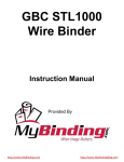
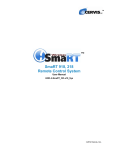
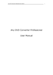
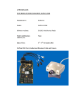
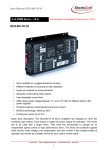
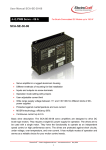
RC4000
Series Reel Control Systems
www.gordoneng.com
revision date 05/17/01
Owner’s Manual
Installation, Operation
and Applications
R ee
lo
rT
http://
e
ak
Up
el or Payof
Dere
f
call toll-free in the US
1.800.315.9233
RC4000 Series Warranty
Five Year Warranty
This product will be repaired or replaced, for five years
from the date of purchase, if it fails to perform to published
specifications.
The product must be used in accordance with the specified
manufacturer’s ratings and must not be physically abused.
All questions related to this warranty should be directed to
the Sales Dept. of Gordon Engineering Corp. See the contact
information below for address, phone, fax and email.
Contact Information
Product Information
Distributor Sales/Support
RC4000 Series Reel Control
Your Distributor’s Phone
Part Number
Your Distributor’s Fax
Serial Number
Your Distributor’s email
Date of Purchase
Factory Sales/Support
Notes
Phone 1.203.775.4501
Fax
1.203.775.1162
email
[email protected]
Factory Mailing Address
Gordon Engineering Corp.
67 Del Mar Drive
Brookfield, CT
06804
USA
i
www.gordoneng.com
1.800.315.9233
Contents
i
Five-Year Warranty
i
Contact Information
ii
Contents
1
Overview
1
Features/Benefits
2-3
Specifications
4-6
Antenna Selection
7
Speed Reduction
8-9
RC4000 Installation
10 - 11
RC4000 Reel Control
page
2
RC4000M Reel Control
page
3
Input/Output Wiring
page
9
Interlocks
page
9
Shock Mounts
page
9
Tuning and Setup
pages 10 - 11
Tuning and Setup
pages 14 - 15
RC4000 Operation
12 - 13
RC4000M Installation
14 - 15
RC4000M Operation
www.gordoneng.com
1.800.315.9233
ii
RC4000 Series Overview
Once the system is properly installed and configured for your
application, the operator simply presses the TUNE button. The
tuning process takes only a few seconds. Then, the operator
positions the payoff or take-up loop within the “V”, either
manually or with the use of the JOG button, so that one of the
green Loop Height indicators is lit. Once these conditions are
met, he/she presses the AUTO/STANDBY button and the system is functional.
Shown with 04A049 Cable
and 04D067 Antenna
Operational Overview
The system is comprised of a control unit, connecting cable
and an antenna assembly. The RC4000 is designed to interface
with third-party motor controllers, while the RC4000M has a
self-contained motor controller.
The control unit determines the load and status of the antenna
assembly and establishes a tuned, RF sensing field around the
antenna elements (yellow, inner pieces). This field is shaped,
through the use of grounded shield elements (black, outer
pieces), and is essentially contained within the “V”.
Features
After your operation is running, you may find that you want to
adjust the loop height, relative to the antenna. This is as easy
as pressing the ADJUST Up or Down buttons located next to
the bargraph indicators. This is done dynamically, with the
motor running.
A pair of selectable relays for HIGH and LOW LIMIT are
included in the control unit. These act in a similar manner to
stand alone models of limit switches, with the exception that
there is no contact with the material required by our limit
relays. The result is non-contact protection against tight or
slack loop conditions, when the relay contacts and the unit
interlocks are properly wired to your control system.
Please direct any questions you have to our Sales Department.
toll-free in US
1.800.315.9233
or
[email protected]
Benefits
RF Sensing Technology
Non-contact, stress-free control of conductive
materials.
Control fine wire, delicate stamped parts
and plated metals, without marring or damage.
Full Line of Modular Antennas
Match your material to our list - it tells you the proper
antenna to choose for your application.
Quick and easy setup and material changes
minimize downtime and maximize profits.
Two-Button Tune and Run
Connect your antenna, press TUNE. Position your loop
so that one green bargraph light is lit. Press the AUTO /
SETUP keypad. You’re running.
The intuitive operator interface requires very little
training, which saves you time and money.
Motor-On, Realtime Loop Height Adjustment
Allows on-the-fly adjustment of loop height.
No need to stop the motor for adjustments to the
loop height; therefore, no lost production.
Integrated High/Low Limit Relays
Ensure against tight or slack loop conditions.
Prevents costly damage to machines, materials and
dies. Eliminates the need for external limit switches.
Variety of Motor Drive Capabilities
RC4000 interfaces with various third-party motor drives.
RC4000M has an integrated motor drive.
RC4000 - access to sophisticated motor drive
options, through use of third-party motor controllers.
RC4000M - delivers economical, basic motor control,
in a single enclosure.
www.gordoneng.com
1.800.315.9233
1
RC4000 Specifications
Input Voltage
Power Consumption
Motor Drive
DC Output Range
Isolation
Keypad Controls
Indicators
SELECT (in setup mode)
push to select reel or dereel mode,
antenna position, and high and low
limit relay activation.
Bargraph: displays loop height
relative to antenna
Limit lights: lit when loop
height exceeds control range
Run light: on when motor function
is active - AUTO or JOG
Tune light: flashes when tuning is
required
on while unit is tuning
flashes with fault light on to indicate
antenna fault
Fault light: indicates a loss of
antenna signal or internal fault
Selection indicators: for reel/ dereel,
antenna position, and high and low
limit relay activation, the indicators
flash to show they are available for
selection. Use the SELECT key to
step through the choices. Use the
ENTER key to set each choice.
Indicators stay lit to show how the
unit is configured.
ENTER (in setup mode)
push to lock in SELECT settings
TUNE (in setup mode)
push to tune system
JOG (in setup mode)
push and release to nudge motor
push and hold to run motor
AUTO/SETUP
push to toggle between setup and
auto modes
ADJUST Up/Down (in auto mode)
allow motor-on, realtime loop height
adjustment
115/230 VAC; 50/60 Hz
3W
provides an isolated, analog input
drive to AC or DC motor controllers
or hysteresis clutch controllers
0 to +10 VDC maximum
0 to +5 VDC minimum
isolated
1000 volts RMS
Enclosure
NEMA 12, industrial plastic
10.2" L x 6.1"W x 4.0"D
(259 mm x 154 mm x 102 mm)
Mounting
vertical or horizontal - to any
bulkhead, chassis or panel
Shipping Weight
Environment
5.5 lbs. (2.5 Kg)
unaffected by dirt, grease,
vibration, etc.
temperature:
0°F - 130°F
humidity:
0 - 95% R.H
RC4000 Dimensions
4 Mounting Holes
clearance holes for
.250" (6mm) bolt
Top View
This is a dimensional drawing of
4.75"
(120.65mm)
the RC4000 enclosure.
6.07"
(154.18mm)
All dimensions are in inches (with
metric equivalents in parentheses).
For mounting instructions and
8.71" (221.23mm)
specifics on shock mounts, please
9.49" (241.05mm)
see the Installation section of the
RC4000 User’s Manual.
1.94"
(49.3mm)
10.21" (259.33mm)
A - Knockout & B - Hole
.860"dia. (21.84mm)
A
1.555"
(39.5mm)
C - Coupler
.50"dia. (12.7mm)
B
C
4.13"
(104.9mm)
2.475"
(62.9mm)
Side View
4.03"
(102.4mm)
Front View - base only
2
www.gordoneng.com
1.800.315.9233
RC4000M Specifications
Input Voltage
115/230 VAC; 50/60 Hz
Power Consumption
1200VA
Motors
directly drives DC shunt wound
or permanent magnet motors
up to 1/2 HP 90 volt armature
or 1 HP 180 volt armature
Interlocks
auto: allows on/off control of
the reel motor by processing
equipment - JOG active
shutoff: allows on/off control of
the reel motor by processing
equipment - JOG inactive
Enclosure
NEMA 12, industrial plastic
10.2" L x 7.8"W x 4.0"D
(259 mm x 199 mm x 102 mm)
Mounting
vertical or horizontal - to any
bulkhead, chassis or panel
Shipping Weight
Indicators
SELECT (in setup mode)
push to select reel or dereel mode,
antenna position, and high and low
limit relay activation.
Bargraph: displays loop height
relative to antenna
Limit lights: lit when loop
height exceeds control range
Run light: on when motor function
is active - AUTO or JOG
Tune light: flashes when tuning is
required
on while unit is tuning
flashes with fault light on to indicate
antenna fault
Fault light: indicates a loss of
antenna or internal fault
Selection indicators: for reel/dereel,
antenna position, and high and low
limit relay activation, the indicators
flash to show they are available for
selection. Use the SELECT key to
step through the choices. Use the
ENTER key to set each choice.
Indicators stay lit to show how the
unit is configured.
ENTER (in setup mode)
push to lock in SELECT settings
TUNE (in setup mode)
push to tune system
6.0 lbs. (2.7 Kg)
Environment
Keypad Controls
unaffected by dirt, grease,
vibration, etc.
temperature:
0°F - 130°F
humidity:
0 - 95% R.H
JOG (in setup mode)
push and release to nudge motor
push and hold to run motor
AUTO/SETUP
push to toggle between setup and
auto modes
ADJUST Up/Down (in auto mode)
allow motor-on, realtime loop height
adjustment
7.30" (185.42mm)
1.75"
(44.45mm)
Fuse
Holder
4 Mounting Holes
clearance holes for
.250" (6mm) bolt
7.82"
(198.63mm)
Top View
RC4000M Dimensions
This is a dimensional drawing of
the RC4000M enclosure.
6.07"
(154.18mm)
All dimensions are in inches (with
4.75"
(120.65mm)
metric equivalents in parentheses).
For mounting instructions and
8.71" (221.23mm)
1.94"
(49.3mm)
9.49" (241.05mm)
10.21" (259.33mm)
A - Knockout & B - Hole
.860"dia. (21.84mm)
A
C
1.75"
(44.45mm)
specifics on shock mounts, please
see the Installation section of the
1.555"
(39.5mm)
C - Coupler
.50"dia. (12.7mm)
B
4.13"
(104.9mm)
RC4000 User’s Manual.
2.475"
(62.9mm)
Side View
4.03"
(102.4mm)
3.00"
(76.2mm)
Front View - base only
www.gordoneng.com
1.800.315.9233
3
RC4000 Series Antenna Selection and Specifications
Once you’ve determined the size of the material you wish to
control, just look at the chart on the next page to select the
proper antenna for your application. Under the heading, Use to
Control, find the size range of the material you need to control.
There are two sizes of “V” antennas for each material size, one
12" in length and one 18" in length.
For applications where the process speed is slow or where the
motor and gear ratio are well matched to the process, a 12"
antenna will provide all the control you need, with the added
bonus of being very compact. Where the process runs at fast
speeds or where dynamic mismatches exist in the application,
you will want to choose an 18" antenna. This provides more
control range and enhances the ability of the RC4000 to compensate for any mismatches in the application.
In applications where wide strips (6" or more in width) are to
be reeled, it is possible to use a flat-plate antenna. These types
of antennas should be positioned directly above or below the
lowest point of the material loop, with the long dimension of
the antenna perpendicular to the direction of travel.
Antenna Selection
Providing the proper antenna for your application is a crucial
part of making the RC4000 Reel Control system perform to its
best abilities. Fortunately, this process has been made easy due in large part to the introduction of our line of modular
antennas.
These modular antennas come with an integrated coupler, and
are designed to be quickly and easily swapped, by unplugging
the locking cable connector. This allows for rapid replacement,
if an antenna is physically damaged, and for quick and easy
setups, in applications where a variety of material sizes are
processed by the same equipment. Process down time is kept
to a minimum, allowing you to maximize productivity.
Coupler Dimensions
04A049 Cable
8' (2.44m) Standard length
other lengths quoted on request
sold separately
2.20" (55.9mm)
For RC4000 Series Reel Controls only
1.25" (31.8mm)
0.40" (10.2mm)
This is a dimensional drawing of
1.00"
(25.4mm)
the 04A035 Coupler.
All dimensions are in inches (with
metric equivalents in parentheses).
These couplers come mounted to
an antenna, but are available for
1.10"
(27.9mm)
G or d o n
Engineering
3.20"
(81.3mm)
Corp.
Brookfield, Connecticut USA
3.10"
(78.7mm)
06804-2494
04A035
Mounting Holes
.190" (4.83mm) dia.
1.25"
(31.75mm)
Antenna Coupler
RC4000/RC4000M
Lot #
ANTENNA SIDE
sale separately. Cables are sold
separately - 8' (2.44m) is standard,
with other lengths available on
request.
4
Separate Cable
w/Locking Connector
Front View
www.gordoneng.com
End View
Side View
1.800.315.9233
RC4000 Series Antenna Selection and Specifications
Type
Length of “V”
Flat
Width
Use to Control
Part Number
V
V
V
V
12" (30.5mm)
18" (45.7mm)
12" (30.5mm)
18" (45.7mm)
0" (0mm)
0" (0mm)
0" (0mm)
0" (0mm)
2" (5.1mm)
2" (5.1mm)
1" (2.54mm)
1" (2.54mm)
fine wire - .5" wire or strip
fine wire - .5" wire or strip
.125"- 1" wire or strip
.125"- 1" wire or strip
04A073
04A074
04A091
04A092
V
V
12" (30.5mm)
18" (45.7mm)
2" (5.1mm)
2" (5.1mm)
1" (2.54mm)
1" (2.54mm)
1"- 3" strip
1"- 3" strip
04A067
04A068
V
V
12" (30.5mm)
18" (45.7mm)
4" (10.2mm)
4" (10.2mm)
1" (2.54mm)
1" (2.54mm)
3"- 5" strip
3"- 5" strip
04A069
04A071
V
V
12" (30.5mm)
18" (45.7mm)
6" (15.2mm)
6" (15.2mm)
1" (2.54mm)
1" (2.54mm)
4"- 7" strip
4"- 7" strip
04A070
04A072
Flat
N/A
12" (30.5mm)
2" (5.1mm)
6" or wider strip
04A088
Mounting Plate dimensions for:
04A073
04A074
04A091
Mounting Plate dimensions for:
04A069
04A071
04A070
04A072
04A088
04A092
04A067
04A068
A
4.10"
(104.14)
A
A
Mounting Plate
04A023
4.50"
(114.3)
Mounting Plate dimensions for:
A
3.70"
(93.98)
#18 hole - .1695" (4.31)
Mounting Plate
04A021
4.50"
(114.3)
All dimensions expressed in
inches and millimeters
A
5.10"
(129.54)
A
A
A
A
3.70"
(93.98)
#18 hole - .1695" (4.31)
All dimensions expressed in
inches and millimeters
A
Mounting Plate
04B013
4.50"
(114.3)
A
All dimensions expressed in
inches and millimeters
7.45"
(189.23)
6.0"
(152.40)
8.2"
(208.28)
A
9.45"
(240.03)
A
5.25"
(133.35)
3.70"
(93.98)
#18 hole - .1695" (4.31)
A
A
A
A
10.2"
(259.08)
Antenna Dimensions
Antenna
Width
Mounting
Plate
Coupler
Cable
The dimensions for all RC4000
Series antennas are listed in the
chart at the top of the page.
All dimensions are in inches (with
V
of
th
ng
Le
metric equivalents in parentheses).
For mounting instructions and
specifics on setup, please see the
Installation section of the RC4000
User’s Manual.
Flat
www.gordoneng.com
1.800.315.9233
5
RC4000 Series Antenna Installation
The length of your coupler cable will determine how far from
the control unit you can position the antenna assembly, but a
minimum distance of three feet (3' or 1 meter) is strongly suggested. This helps to ensure that the operator’s body is not
close enough to the antenna to affect the tuning. The standard
cable length is eight feet (8' or 2.4 meters), and optional lengths
of fifteen feet (15' or 4.6 meters) and twenty-five feet (25' or
7.62 meters) are readily available.
Mount your antenna so the material runs through the middle of
the “V” and the lowest point of the loop is either directly above
or below the coupler, depending on whether you are looking up
or down, respectively. The antenna should be securely
mounted, with either four (4) or six (6) #8 machine screws,
flat and lock washers, as required.
The illustrations below depict both direct and indirect methods
of sensing the material loop.
Antenna Installation
Once you’ve selected the proper antenna for your application,
you will need to decide whether you want to “look up” or
“look down” at the material loop. The RC4000 Selection
Mode allows you to configure the control for either scenario,
whether you are in Reel or Dereel mode.
Direct Control of Conductive
Materials
We strongly suggest that you employ the selectable High
and Low Limit Relays, as an added level of safety. This will
ensure against tight loop or excessive payoff conditions, if a
control or process problem should occur (e.g. material breaks
or runs out, or something moves or damages the antenna).
These relays fulfill the same function as stand alone limit
switches, when properly wired to your control system.
d
Sensing Field
Indirect Control
V Antenna w/12A844 Coupler
This illustration depicts one way that a
nonconductive material could be controlled
using an RC4000 Series Reel Control.
An idler pulley, that rides on the material, is
used to transfer the loop height information
to a grounded metal target, which travels up
and down within the “V” of the antenna.
Many variations of this approach are
possible, and they can be as simple as a
grounded metal weight or target suspended
from the material loop within the “V” of
the antenna.
6
6"
Idler Pulley
Guide Rails
www.gordoneng.com
Grounded
Metal Target
1.800.315.9233
Speed Reduction
Since the feed-rate in most applications
requires much less than standard 1725 RPM DC
motor speed, you must connect a speed reducer
between the motor and the reel. You can use the
following formula to calculate gear ratios.
R=
S(3.14)d
F
Where:
R = step-down ratio between motor and reel
F = maximum machine feed-rate (units of measure/min)
d = reel hub diameter (units of measure)
S = motor speed (RPM)
In order to allow some margin for feed-rate
increase, a motor speed (S) less than maximum
should be used; for example, for a motor rated at
1725 RPM, calculate the ratio for 1500 RPM.
Sample Calculation:
(1500)(3.14)(6)
= 28.2
1000
Where:
S = 1500 RPM
F = 1000 units of measure/min
d = 6 units of measure
Checklist
Note the Speed (S) at which your motor
is rated to operate here (
RPM)
and in the top line of the formula below.
Note your Reel Hub Diameter (d)
units of measure) and in the
here (
top line of the formula below.
Note the Feed Rate (F) of your
units of measure/min)
machine here (
and in the bottom line of the formula below.
R=
(
) (3.14) (
(
)
)
Note the Step Down Ratio (R) of
your machine below - round
your answer to the nearest
whole number.
R=
: 1
Checklist
Speed Reduction
is Required for Most
Applications
www.gordoneng.com
1.800.315.9233
7
RC4000 Installation
Antenna/Coupler Assembly
For most reeling applications, you can mount your antenna in
a “looking-up” configuration, with the Reel mode selected.
For specifics on mounting the antenna/coupler assembly, refer
to page 6.
In dereel applications, if the material breaks it may be pulled
from the sensing field by the machine processing the material.
This will cause the dereel motor to pay off material onto the
floor. If you wish to ensure against this, you should activate the
High and Low Limit Relays.
Coupler Cable
Control Unit
If you have a standard 04A049 coupler cable, your control unit
must be mounted within eight feet of your antenna; however,
if a remote location for your control is required, you can order
cables with special cable lengths of fifteen or twenty-five feet
(04A049-15 and 04A049-25, respectively). For convenience
during setup, the control unit should be as close to the machine
and motor controls as possible, but a minimum distance of
three feet from the antenna should be maintained. This should
be a sufficient distance to prevent tuning errors that can be
caused by the presence of the operator in the sensing field.
You shouldn’t mount the control unit directly onto a machine
that has an excessive amount of vibration, as this can cause
mechanical failure of some components. If you have no alternative and the control must be mounted on a machine that
vibrates, soft shock mounts must be used. Please ask for our
03A155 Shock Mount Kit (see page 9).
The cable has locking connectors on both ends, to make
replacement of the antenna or the control fast and easy. Plug
one end into the antenna and other into the control, screw down
the locking collars and you’re ready to go.
If you elect to enclose your coupler cable in a conduit, it should
not share a conduit with high voltage lines, as this could create
a situation where interference from the high voltage lines
affects the coupler voltage and degrades the performance of the
system.
Gear Box Ratio
The gearbox ratio, for speed reduction between motor and reel,
must be calculated according to the formula on Page 7. If your
step-down ratio is too low for the application, the system will
be overly sensitive and tend to exhibit jerkiness instead of a
smooth control of the material.
RC4000 Dimensions
4 Mounting Holes
clearance holes for
.250" (6mm) bolt
Top View
This is a dimensional drawing of
4.75"
(120.65mm)
the RC4000 enclosure.
6.07"
(154.18mm)
All dimensions are in inches (with
metric equivalents in parentheses).
8.71" (221.23mm)
Use ¼-20 bolts and flat washers to
mount the control unit. If there is
moderate to heavy vibration, use
an 03A155 Shock Mount Kit.
1.94"
(49.3mm)
9.49" (241.05mm)
10.21" (259.33mm)
A - Knockout & B - Hole
.860"dia. (21.84mm)
A
1.555"
(39.5mm)
C - Coupler
.50"dia. (12.7mm)
B
C
4.13"
(104.9mm)
2.475"
(62.9mm)
Side View
4.03"
(102.4mm)
Front View - base only
8
www.gordoneng.com
1.800.315.9233
RC4000 Installation
Power Input Wiring
Auto Interlock
All power wires must be brought into the box through the .860"
(21.8mm) hole on the left side, using a suitable ½" (13mm)
electrical fitting. Wire size must conform to local electrical
code requirements for 1 ampere (normally #14 AWG will meet
these requirements).
This feature allows external on-off control of the reel motor in
AUTO mode only. To use this function, connect the AUTO and
COM terminals to a relay contact that closes when reel motor
stop is required. The Auto LED blinks to indicate the interlock
is asserted, and since the unit is temporarily in SETUP mode,
the JOG feature can be used. When the AUTO interlock is
released, the control returns to AUTO mode without
operator intervention.
Set the 115/230 volt selector switch to the proper position.
Connect three-wire 115 or 230 VAC, single phase power to
terminals 1, 2 and 3. Terminal 1 must be well grounded to a
common electrical ground. The AC line power must be supplied from a disconnect box that is either fused or equipped
with circuit breakers.
Output Wiring
The RC4000 requires a separate external motor control to drive
the reel motor. The control voltage is taken from the Isolated
DC Output Terminals. Select the +5 or +10 volt range, as
required by your controller.
In general, all wire should be heavy enough to accept crimped,
push-on style terminals and to withstand the rigors of your
production environment. We recommend shielded twisted pair,
with the shield grounded at the control unit end only. These
wires should not be run through conduit with high voltage
lines.
Shut-off Interlock
This feature allows external shut-off control of the reel motor
in both Auto and Manual modes. To use this feature, connect
the SHUT OFF and COM terminals to a relay contact that
closes when reel motor stop is required. The AUTO and
SETUP LEDs both blink as long as the contacts are closed.
When the contacts open, the unit stays in SETUP mode until
the AUTO key is pushed by the operator.
Relay Outputs
The Operation section describes the procedure for enabling
the High and Low Limit Relays. Connections must be made to
output terminals 8, 9, and 10, to utilize this feature. Connect to
the COM and either the NO or the NC terminal, depending on
the control function to be performed.
Wiring Terminals
for RC4000
and RC4000M
03A155 - Shock Mount Kit
03A155 SHOCK MOUNT KIT
CAUTION! DO NOT
OVERTIGHTEN!
Nut
Our 03A155 shock mount kits
Lockwasher
3/4" Washer
contain Lord Corporation’s
Box
Mounting Flange
# SMB006-0100-7 shock mounts.
Shock Mount
We recommend that you use these
or their equivalents, whenever the
Press
Mounting Bracket
control unit is mounted in a high
vibration environment.
Lockwasher
Nut
www.gordoneng.com
1.800.315.9233
9
RC4000 Operation
Keypad Controls
Indicators
Indicators
SELECT (in setup mode)
push to select reel or dereel mode,
antenna position, and high and low
limit relay activation.
Bargraph: displays loop height
relative to antenna
Tune light: flashes when tuning is
required
on while unit is tuning
flashes with fault light on to indicate
antenna fault
ENTER (in setup mode)
push to lock in SELECT settings
TUNE (in setup mode)
push to tune system
JOG (in setup mode)
push and release to nudge motor
push and hold to run motor
Manual Speed Mode - push and hold,
simultaneously press Enter
use Adjust Up/Down to adjust speed any other key terminates this mode
AUTO/SETUP
push to toggle between setup and
auto modes
Limit lights: lit when loop
height exceeds control range
Run light: on when motor function
is active - AUTO or JOG
Auto light: on when unit is in the
Auto mode - reel motor is controlled
by antenna information
flashes to indicate auto interlock is
engaged
flashes with standby light to indicate
shutoff interlock is engaged
Setup light: on when unit is in the
Setup mode - reel motor is controlled
by Jog function or Manual Speed mode
flashes with standby light to indicate
shutoff interlock is engaged
Fault light: indicates a loss of
antenna signal or internal fault
Selection indicators: for reel/dereel,
antenna position, and high and low
limit relay activation, the indicators
flash to show they are available for
selection
Use the SELECT key to step through
the choices
Use the ENTER key to set each choice
Indicators stay lit to show how the
unit is configured
ADJUST Up/Down (in auto mode)
allow motor-on, realtime loop height
adjustment
Control Interface
This is an illustration
of the RC4000 Series
control interface.
Indicators and Keypad
Functions are defined
above.
10
www.gordoneng.com
1.800.315.9233
RC4000 Operation
SYSTEM CONFIGURATION
AUTO
The Reel Control always powers up in SETUP mode, and this
is expressed by the SETUP indicator being lit. The system
configuration is expressed by the yellow indicators in the blue
area of the panel. These can be set as follows:
Ensure that your line is operational and that all personnel are
clear of any hazardous areas. Then, press the AUTO/SETUP
key to put the system into Auto mode.
Press the SELECT key. The indicators which represent the
selected configuration will blink. Each subsequent entry of the
SELECT key will toggle to the next configuration choice, and
its corresponding indicators will blink. When the desired
system configuration is displayed, press ENTER, and the new
settings will be stored in memory.
Next the High Limit Relay indicators will blink. Press the
SELECT key repeatedly until the desired configuration is
indicated. Choose a dimly blinking indicator if you wish to
disable the relay function, or a brightly blinking one to enable
the relay function. Press ENTER to save settings. Repeat for
the Low Limit Relay. These settings will remain in effect until
this process is repeated.
TUNE
Each combination of antenna and material requires tuning of
the system, for proper operation. First, ensure your antenna is
positioned and installed according to the instructions on page
6; then, remove the material from the field and press TUNE.
The TUNE indicator will remain on during the tuning process
and will go off when the unit is successfully tuned.
If for any reason proper tuning cannot be achieved, the FAULT
indicator will light, Auto operation will be locked out, and
TUNE indicator will blink. Refer to the section on FAULTS.
Any subsequent operation of the TUNE key turns off the
FAULT indicator and initiates another tuning procedure.
Position the material in the sensing field, so that one of the
green bargraph lights is lit (you may move the material through
the sensing field either manually or with the JOG key).
The AUTO and RUN indicators will light. The reel speed
should automatically follow the feed rate of the material.
In the REEL mode with the antenna below or DEREEL mode
with antenna above, ensure the motor stops when the material
reaches the farthest distance away from the antenna. Use the
ADJUST keys to bring the loop back towards the antenna until
it always stops when the associated Limit indicator lights.
Note: The ADJUST keys only function when the motor is
running and are limited to the green range of the bargraph.
In the DEREEL mode with antenna below or REEL mode with
antenna above, operation is reversed and the motor should stop
when the material is close to, but not touching, the antenna.
Use the ADJUST keys to place the loop farther away from
the antenna, until it always stops when the associated Limit
indicator lights.
We strongly suggest that you employ the selectable High
and Low Limit Relays, as an added level of safety. This will
ensure against tight loop or excessive payoff conditions, if a
control or process problem should occur (e.g. material breaks
or runs out, or something moves or damages the antenna).
These relays fulfill the same function as stand alone limit
switches, provided they are properly wired to your control
system.
FAULTS
Any detectable condition that will prevent proper operation
will be indicated by the FAULT Indicator being lit. When this
occurs, AUTO operation will be locked out. Fault conditions
are as follows:
Fault + Flashing TUNE Indicator
JOG
The JOG function is enabled only when the unit is in SETUP
mode. Pressing the JOG key causes the motor to run at an
increasing speed, until the key is released and the motor stops.
For Manual Speed Control, press JOG until the desired speed
is reached, then press ENTER. The ADJUST Up and Down
keys allow the speed to be fine tuned. Pressing any other key
than ADJUST Up or Down disables this function.
www.gordoneng.com
Indicates inability to tune properly
Cable and/or antenna not connected
Short or open circuit in cable or antenna
Grounded metal or a person touching the antenna
Flashing FAULT Indicator
Indicates loss of System Synchronization
Unit must be powered down and restarted
If problem persists, try filtering power input lines
If problem still persists, call factory for assistance
1.800.315.9233
11
RC4000M Installation
Antenna/Coupler Assembly
For most reeling applications, you can mount your antenna in
a “looking-up” configuration, with the Reel mode selected.
For specifics on mounting the antenna/coupler assembly, refer
to page 6.
In dereel applications, if the material breaks it may be pulled
from the sensing field by the machine processing the material.
This will cause the dereel motor to pay off material onto the
floor. If you wish to ensure against this, you should activate the
High and Low Limit Relays.
Coupler Cable
Control Unit
If you have a standard 04A049 coupler cable, your control unit
must be mounted within eight feet of your antenna; however,
if a remote location for your control is required, you can order
cables with special cable lengths of fifteen or twenty-five feet
(04A049-15 and 04A049-25, respectively). For convenience
during setup, the control unit should be as close to the machine
and motor controls as possible, but a minimum distance of
three feet from the antenna should be maintained. This should
be a sufficient distance to prevent tuning errors that can be
caused by the presence of the operator in the sensing field.
You shouldn’t mount the control unit directly onto a machine
that has an excessive amount of vibration, as this can cause
mechanical failure of some components. If you have no alternative and the control must be mounted on a machine that
vibrates, soft shock mounts must be used. Please ask for our
03A155 Shock Mount Kit (see page 13).
RC4000M Dimensions
The cable has locking connectors on both ends, to make
replacement of the antenna or the control fast and easy. Plug
one end into the antenna and other into the control, screw down
the locking collars and you’re ready to go.
If you elect to enclose your coupler cable in a conduit, it should
not share a conduit with high voltage lines, as this could create
a situation where interference from the high voltage lines
affects the coupler voltage and degrades the performance of the
system.
Gear Box Ratio
The gearbox ratio, for speed reduction between motor and reel,
must be calculated according to the formula on Page 7. If your
step-down ratio is too low for the application, the system will
be overly sensitive and tend to exhibit jerkiness instead of a
smooth control of the material.
7.30" (185.42mm)
1.75"
(44.45mm)
Fuse
Holder
This is a dimensional drawing of
7.82"
(198.63mm)
Top View
the RC4000M enclosure.
6.07"
(154.18mm)
All dimensions are in inches (with
4.75"
(120.65mm)
metric equivalents in parentheses).
Use ¼-20 bolts and flat washers to
8.71" (221.23mm)
an 03A155 Shock Mount Kit.
1.94"
(49.3mm)
9.49" (241.05mm)
mount the control unit. If there is
moderate to heavy vibration, use
4 Mounting Holes
clearance holes for
.250" (6mm) bolt
10.21" (259.33mm)
A - Knockout & B - Hole
.860"dia. (21.84mm)
A
C
1.75"
(44.45mm)
1.555"
(39.5mm)
C - Coupler
.50"dia. (12.7mm)
B
4.13"
(104.9mm)
2.475"
(62.9mm)
Side View
4.03"
(102.4mm)
3.00"
(76.2mm)
Front View - base only
12
www.gordoneng.com
1.800.315.9233
RC4000M Installation
Power Input Wiring
- once again, be sure to observe the polarity of the terminals
and your field wires.
All power wires must be brought into the box through the .860"
(21.8mm) hole on the left side, using a suitable ½" (13mm)
electrical fitting. Wire size must conform to local electrical
code requirements for 8 amperes (normally #14 AWG will
meet these requirements).
Modification 04A060 must be installed on any RC4000M Reel
Control that is intended for use with Form Factor 1.0 motors
(Bodine Electric has a line of these), as follows:
Set the 115/230 volt selector switch to the proper position.
Connect three-wire 115 or 230 VAC, single phase power to
terminals 1, 2 and 3. Terminal 1 must be well grounded to a
common electrical ground. The AC line power must be supplied from a disconnect box that is either fused or equipped
with circuit breakers.
04A060-1
04A060-2
04A060-3
for1/50, 1/20 & 1/12 HP
for 1/8 HP
for 1/4 HP
In general, all wire should be heavy enough to accept crimped,
push-on style terminals and to withstand the rigors of your
production environment.
Auto Interlock
Output Wiring
If you use a permanent magnet motor in your application,
connect the motor armature wires to terminals 4 and 5 - please
note the polarity of the terminals and your armature wires - if
you reverse the polarity, your motor will run in the opposite
direction. Terminals 6 and 7 are not used with permanent
magnet motors.
If you use a shunt wound motor for your application, connect
the motor armature wires to terminals 4 and 5 - please note the
polarity of the terminals and your armature wires - if you
reverse the polarity, your motor will run in the opposite direction. Then, connect the motor field wires to terminals 6 and 7
This feature allows external on-off control of the reel motor in
AUTO mode only. See page 9 for details.
Shut-off Interlock
This feature allows external shut-off control of the reel motor
in both Auto and Manual modes. See page 9 for details.
Relay Outputs
The Operation section describes the procedure for enabling
the High and Low Limit Relays. See page 9 for details.
Wiring Terminals
for RC4000
and RC4000M
03A155 - Shock Mount Kit
03A155 SHOCK MOUNT KIT
CAUTION! DO NOT
OVERTIGHTEN!
Nut
Our 03A155 shock mount kits
Lockwasher
3/4" Washer
contain Lord Corporation’s
Box
Mounting Flange
# SMB006-0100-7 shock mounts.
Shock Mount
We recommend that you use these
or their equivalents, whenever the
Press
Mounting Bracket
control unit is mounted in a high
vibration environment.
Lockwasher
Nut
www.gordoneng.com
1.800.315.9233
13
RC4000M Operation
Keypad Controls
Indicators
Indicators
SELECT (in setup mode)
push to select reel or dereel mode,
antenna position, and high and low
limit relay activation.
Bargraph: displays loop height
relative to antenna
Tune light: flashes when tuning is
required
on while unit is tuning
flashes with fault light on to indicate
antenna fault
ENTER (in setup mode)
push to lock in SELECT settings
TUNE (in setup mode)
push to tune system
JOG (in setup mode)
push and release to nudge motor
push and hold to run motor
Manual Speed Mode - push and hold,
simultaneously press Enter
use Adjust Up/Down to adjust speed any other key terminates this mode
AUTO/SETUP
push to toggle between setup and
auto modes
Limit lights: lit when loop
height exceeds control range
Run light: on when motor function
is active - AUTO or JOG
Auto light: on when unit is in the
Auto mode - reel motor is controlled
by antenna information
flashes to indicate auto interlock is
engaged
flashes with standby light to indicate
shutoff interlock is engaged
Setup light: on when unit is in the
Setup mode - reel motor is controlled
by Jog function or Manual Speed mode
flashes with standby light to indicate
shutoff interlock is engaged
Fault light: indicates a loss of
antenna signal or internal fault
Selection indicators: for reel/dereel,
antenna position, and high and low
limit relay activation, the indicators
flash to show they are available for
selection
Use the SELECT key to step through
the choices
Use the ENTER key to set each choice
Indicators stay lit to show how the
unit is configured
ADJUST Up/Down (in auto mode)
allow motor-on, realtime loop height
adjustment
Control Interface
This is an illustration
of the RC4000 Series
control interface.
Indicators and Keypad
Functions are defined
above.
14
www.gordoneng.com
1.800.315.9233
RC4000M Operation
SYSTEM CONFIGURATION
AUTO
The Reel Control always powers up in SETUP mode, and this
is expressed by the SETUP indicator being lit. The system
configuration is expressed by the yellow indicators in the blue
area of the panel. These can be set as follows:
Ensure that your line is operational and that all personnel are
clear of any hazardous areas. Then, press the AUTO/SETUP
key to put the system into Auto mode.
Press the SELECT key. The indicators which represent the
selected configuration will blink. Each subsequent entry of the
SELECT key will toggle to the next configuration choice, and
its corresponding indicators will blink. When the desired
system configuration is displayed, press ENTER, and the new
settings will be stored in memory.
Next the High Limit Relay indicators will blink. Press the
SELECT key repeatedly until the desired configuration is
indicated. Choose a dimly blinking indicator if you wish to
disable the relay function, or a brightly blinking one to enable
the relay function. Press ENTER to save settings. Repeat for
the Low Limit Relay. These settings will remain in effect until
this process is repeated.
TUNE
Each combination of antenna and material requires tuning of
the system, for proper operation. First, ensure your antenna is
positioned and installed according to the instructions on page
6; then, remove the material from the field and press TUNE.
The TUNE indicator will remain on during the tuning process
and will go off when the unit is successfully tuned.
If for any reason proper tuning cannot be achieved, the FAULT
indicator will light, Auto operation will be locked out, and
TUNE indicator will blink. Refer to the section on FAULTS.
Any subsequent operation of the TUNE key turns off the
FAULT indicator and initiates another tuning procedure.
Position the material in the sensing field, so that one of the
green bargraph lights is lit (you may move the material through
the sensing field either manually or with the JOG key).
The AUTO and RUN indicators will light. The reel speed
should automatically follow the feed rate of the material.
In the REEL mode with the antenna below or DEREEL mode
with antenna above, ensure the motor stops when the material
reaches the farthest distance away from the antenna. Use the
ADJUST keys to bring the loop back towards the antenna until
it always stops when the associated Limit indicator lights.
Note: The ADJUST keys only function when the motor is
running and are limited to the green range of the bargraph.
In the DEREEL mode with antenna below or REEL mode with
antenna above, operation is reversed and the motor should stop
when the material is close to, but not touching, the antenna.
Use the ADJUST keys to place the loop farther away from
the antenna, until it always stops when the associated Limit
indicator lights.
We strongly suggest that you employ the selectable High
and Low Limit Relays, as an added level of safety. This will
ensure against tight loop or excessive payoff conditions, if a
control or process problem should occur (e.g. material breaks
or runs out, or something moves or damages the antenna).
These relays fulfill the same function as stand alone limit
switches, provided they are properly wired to your control
system.
FAULTS
Any detectable condition that will prevent proper operation
will be indicated by the FAULT Indicator being lit. When this
occurs, AUTO operation will be locked out. Fault conditions
are as follows:
Fault + Flashing TUNE Indicator
JOG
The JOG function is enabled only when the unit is in SETUP
mode. Pressing the JOG key causes the motor to run at an
increasing speed, until the key is released and the motor stops.
For Manual Speed Control, press JOG until the desired speed
is reached, then press ENTER. The ADJUST Up and Down
keys allow the speed to be fine tuned. Pressing any other key
than ADJUST Up or Down disables this function.
www.gordoneng.com
Indicates inability to tune properly
Cable and/or antenna not connected
Short or open circuit in cable or antenna
Grounded metal or a person touching the antenna
Flashing FAULT Indicator
Indicates loss of System Synchronization
Unit must be powered down and restarted
If problem persists, try filtering power input lines
If problem still persists, call factory for assistance
1.800.315.9233
15
Call the Pioneers of Capacitive, Presence
Sensing Technology
for Your Reeling and Guarding Solutions.
Call Gordon Engineering.
There’s always a knowledgeable person at Gordon
Engineering to answer your questions.
When you need to guard perimeters or complex
machines, such as four-slides or automatic presses,
call us. When you need a Brake Monitor for your
mechanical power press, our engineers will gladly
assist you in solving your application problem. We
also make a full range of inductive ring sensors.
For price and delivery, call our sales department or
the regional distributor listed below.
Don’t forget our Five-Year Guarantee - it comes with
every RC4000 Series Reel Control we sell, and we offer a
30-day Free Trial on all standard products.
toll-free
call
fax
email
website
R
E
E
L
1.800.315.9233
1.203.775.4501
1.203.775.1162
[email protected]
www.gordoneng.com
C
O
N
T
R
O
L
S
distributed by:
Part # 04A107
Gordon Engineering Corp.
67 Del Mar Drive
Brookfield, CT
USA
06804-2494
www.gordoneng.com
G or d o n
Engineering
Corp.