1
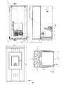
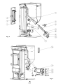
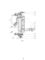
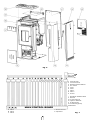
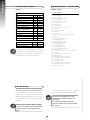
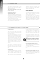
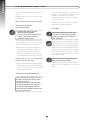
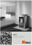
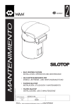
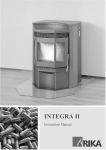
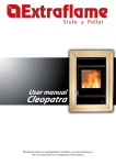
VISIO
M A N U A L
R I K A - K A M I N Ö F E N
Die Seele Ihres Heimes
Combustion air connection
Exhaust gas connection
Fig. 2
Fig. 1
2
Fig. 3
Fig. 4
3
Fig. 5
4
Fig. 6
yellow/green
blue
brown
a
3
2
1
4
5 6 7 8 9 VII VI
V
IV
III
II
PE yellow/green
b
A
B
C
I
PE
N
L
1
2
3
4
5
6
7
8
9
HAL-RG-Fan
Control board
Remote-fixed network
Air sensor
UTB
OTB
FKY 1
FKY 2
Alarm
I
II
III
IV
V
VI
VII
Network 230VAC 50Hz
RG-Fan
Cross flow fan
Ignition element
Auger motor
Circulating pump
Reserve
MAIN CONTROL BOARD
a Fine-wire fuse
b Capacitor
A Bus 1
B Bus 2
C Bus 3
Fig. 7
5
E NG LI S H
T A
B
L
E
O F
C O N T E
N T S
Overview of technical data and spare parts
8
1. I M P O R TA N T I N F O R M AT I O N
General warning and safety instructions
9
2 . W H AT A R E P E L L E T S ?
Pellet storage
9
3. TECH NOLOGY
Operating comfort - Operating security
10
Highest efficiency - Lowest emissions
10
4 . A U T O M AT I C S A F E T Y F U N C T I O N S
Power failure
10
Overheating
10
Low temperature switch off
10
Electric excess current cut out
10
5 . I N S TA L L I N G T H E E N C L O S E D F I R E
Genral information
11
Making the flue connection
11
11
Method
Floor protection
11
Safety distances
11
Electrical connection
12
Combustion air
12
Feeding external combustion air
12
6. F IT TI NG OPTIONS
General
13
Fitting the steel or ceramic front cladding ,
ceramic lid with insert
13
Fitting convection fan (optional)
13
7. O P E R AT I O N
Basic information
14
Control and internal control unit - function
14
14
Internal control unit
14/16
Possible operating ranges
Using the heater for the first time
16
16/17
Stopping the heater
External control unit with room temperature probe
17
(Pellet-Control-Optional)
6
E NG LI S H
8. E LECTRON IC IG N ITION
Heating up without electric ignition
18
Some field values
18
Adding fuel
18
9. MAINTENANCE AND CLEANING
Basic information
19
Operating handle
19
Wood as fertiliser
19
Cleaning the fire grate
19
Cleaning the fire door
19
Cleaning the exhaust air flues
19/20
Cleaning the exhaust air manifold
20/21
Cleaning the exhaust air fan housing
21
Cleaning the pellet container
21
Inspecting the door seal
21
Checking the chimney connection
21
Cleaning the air sensor
21
10 . FA U LT F I N D I N G A N D S O L U T I O N S
Problems - Causes - Possible Solutions
22/23
11. A P P E N D I X
Menu driven operation for programming the internal control
24
12 . G U A R A N T E E
We guarantee
27
Guarantee card
27/28
E X P L A N A T I O N
Important instructions
Practical advice
Use the fold out plan for assistance
7
O F
S Y M B O L S
S PA R E PA R T S - O V E R V I E W
(Fig. 1)
(Fig. 3 - Fig. 7)
DESCRIPTION
TECHNICAL DATA
Height
[mm]
1031
Width
[mm]
530
Depth
[mm]
600
Weight without casing
[daN]
130
Weight with steel front
[daN]
137
Weight with ceramic front
[daN]
142
Smoke tube pipe diameter
[mm]
100
Heating performance range
[kW]
2,4 - 8
Room heating capacity (m3)
dependent on house insulation
Fuel consumption
Pellet container capacity
Power supply
[m3]
50 - 220
[kg/h]
0,6 - 1,8
[kg]
32
[V]; [Hz] 230; 50
Average electrical power consumption
[W]
< 100
Fuse
[A]
1,6 T
Exhaust air mass flow
[g/s]
6.0 - 6.0
Exhaust air temperature
[°C]
1 57 - 229
Chimney draft requirement
[Pa]
0-0
The owner of the pellet heater is required
to retain the technical documentation and
to present it on demand for inspection by
the authorities or the chimney sweep.
01
02
03
04
05
06
07
08
09
10
11
Fire door
Fire door seal
Fire door glass
Upper temperature limiter
Ignition element
Conveyorscrew complete
Centring plate
Motor plate
Hexagonal bolt
Conveyor screw drive motor
Air sensor
20
21
22
23
Internal control unit
Main fuse
Main board
Remote fixed network board (optional)
30
31
32
33
34
35
36
37
38
39
40
41
42
43
44
45
46
47
48
49
50
Wing nut
Flue gas shaft cleaning lid
Intermediate bottom
Top/bottom cleaning lid
Exhaust gas fan housing
Exhaust gas fan motor
Hexagonal screws
Low temperature switch
Smoke tube adapter 100 mm
Fire door hinge
Container lid (with rating plate, warning sign)
Rear wall
Side cladding rear right complete
Rear wall cover
Mains cable with earthed plug
Corner post front right complete
Front cladding bottom
Front cladding top
Corner post front left complete
Side cladding rear left complete
Ceramic lid with insert
PAC K AG I N G
Your first impression is important to us!
- The packaging used for your domestic
- The packaging of your new domestic
heater is mainly environmentally neutral.
heater offers excellent protection against
The wood in the packaging is not surface
treated and can therefore be burnt in your
pellet heater.
The cardboard and sheeting (PE) can be
disposed of at public refuse disposal facilities
for re-cycling.
damage. Nevertheless, damage can occur to
the heater and the accessories during transportation.
Therefore please check your heater on receipt
to ensure it is complete and free from damage!
Inform your dealer of any shortfalls without
delay!
8
Subject to technical and optical modifications as well as typographical errors and misprints.
E NG LI S H
T E C H N I C A L DATA
GENERAL WARNING AND
SAFETY INSTRUCTIONS
Do not touch these parts without the rele-
The introductory general warning and
safety instructions must be unconditionally observed
protective gloves or operating materials
Read the whole manual thoroughly be-
particular danger and keep them away
vant protective clothing or aids such as heat
(cold hand).
➧
➧
fore using the fire for the first time.
➧
from the heating device during operation.
Only approved transport aids with ade-
➧
quate carrying capacity may be used to
➧
Do not put washing on the fire to dry.
➧
Stands for drying items of clothing or
Your heating device is not suitable for use
as a ladder or to stand on.
➧
Do not place non-heat resistant items on
the heating device or in its vicinity.
transport the heating device.
➧
Ensure that children are aware of this
suchlike must be set up at an adequate
Burning fuels releases heat energy that
distance from the heating device - fire
leads to the surface of the pellet heater, as
hazard!
well as the doors, the door and operating
➧
handles, the door glass, the smoke tubes
Processing easily inflammable or explo-
sive substances in the same of adjoining
and occasionally the front wall of the hea-
rooms is prohibited when the heating device
ting device heating up.
is in operation.
2 . W H AT A R E P E L L E T S ?
Pellets are made from wood waste from
Please request the tested fuel and a list of
monitored fuel producers from your pellet fire
consultant.
Using poor quality or prohibited pellet fuel
influences the function of your fire and can
further lead to the guarantee and the product
liability becoming invalid.
saw- and planing mills as well as brash from
forestry operations. These „starting products“ are crushed, dried and pressed into
„fuel“ pellets without any binding agent.
SPECIFICATIONS FOR HIGH QUALITY
PELLETS:
PELLET STORAGE
Thermal value:
Density:
Water content:
Ash content:
Diameter:
Length:
Contents:
Packaging:
5.3 kWh/kg
700 kg/m3
max. 8 % of the weight
max. 1% of the weight
5 - 6.5 mm
max. 30 mm
100 % wood, untreated and without
any binding agent (proportion of bark
max. 5 %)
in sacks made from environmentally
friendly or biologically degradable
plastic or from paper (2 - 3 layer/
similar to cement packaging)
The fuel must be stored as dry as possible
in order to guarantee problem free burning
of the wood pellets.
9
E NG LI S H
1. I M P O R TA N T I N F O R M AT I O N
E NG LI S H
3. TECH NOLOGY
The advanced technological state of your
Operation is reduced to a minimum - this
pellet fire is the result of years of tests in
means no operating errors with optimum
laboratory and practice.
operation at the same time.
The practical advantages of your pellet
HIGHEST EFFICIENCY LOWEST EMISSIONS
fire are convincing:
OPERATING COMFORT OPERATING SECURITY
A very large heat exchanger surface together
The fire is controlled by a digital electronic
results in very good use of fuel.
with an optimum combustion air control
Finely dosed pellet feed in an optimised
monitoring device together with a patented
burner pot made from high quality cast
„air sensor“ that controls the interaction of
steel results in almost perfect combustion
a flue gas fan, worm conveyor, convection
with very good exhaust gas values - and that
fan and temperature monitoring.
is guaranteed in every phase of operation.
This monitoring system guarantees an optimum combustion and operating state.
4 . A U T O M AT I C S A F E T Y F U N C T I O N S
However whether heating operation is
POWER FAILURE
continued depends on the embers still in
After a brief power failure the operating
the combustion pan. If no ignition takes
functions that were set before the power
place when fuel feed is started again, then
failure are continued.
the shutdown programme (cleaning , after-
ON-mode (manual operation): The control
running phase) is carried out. The fire must
switches into ST (start phase) and the de-
be started again dependent on the pre-set
vice then continues to run in ON-operation.
mode.
TM-mode (automatic operation): The contol
switches into ST (start phase) and the de-
CAUTION! If the fire overheats it is imperative
that maintenance and cleaning work is carried
out.
vice then continues to run in TM-operation.
SB-mode (Standby-operation): The control
switches into SB operation after approx. 2
seconds.
LOW TEMPERATURE SWITCH OFF
Some smoke can be emitted when the
The fire switches off if it cools down below
power fails. This does not last any longer
a minimum temperature.
than three to five minutes and is not a safety
It can also switch off if starting takes too
risk.
long.
OVERHEATING
ELECTRIC EXCESS CURRENT CUT OUT
An excess temperature switch (OTB) switches the heater off automatically in the
The fire is fitted with a main fuse (on the
case of overheating. After the fire has cooled
rear of the fire) as protection against excess
down it returns to the control programme.
current (Data as per Item 1)
10
MAKING THE FLUE CONNECTION
(Fig. 1)
GENERAL INFORMATION
The fire must be connected to a chimney
that has been approved for solid fuel. The
Method
chimney must have a diameter of at least
1. Measure out and mark the fire connec-
120 mm.
tion (taking any floor plate thickness into
The flue gas system is based on underpres-
consideration) (Fig. 1)
sure in the combustion chamber and a light
2. Chisel out (drill) the hole in the wall
excess pressure on the flue gas outlet. It is
3. Seal in wall lining
therefore important that the flue gas con-
4. Connect fire with the smoke tube to the
nection is fitted correctly and in an airtight
chimney
manner.
FLOOR PROTECTION
Only use heat resistant sealing materials, as
well as heat resistant silicon and mineral wool.
The fire must be installed on a fire resistance surface. A fire resistant underlay
(steel plate, ceramic or similar) is required
We recommend that only the authorised specialist company carries out fitting (or inspection
and approval in the case of own installation).
for flammable floors (wood, carpet etc.).
Minimum dimensions for a relevant
underlay (floor plate):
Please also ensure that the smoke tube
does not jut out into the free cross section
From the fire chamber opening to the
in the chimney.
front:
50 cm
ATTENTION! Please follow locally valid building
regulations.
Contact your chimney sweep for information on
this.
From the fire chamber opening to the left
and right:
30 cm (each side)
Avoid extraction routes to the chimney
SAFETY DISTANCES
that are too long.
(Fig. 2)
Avoid too many changes in the direction of
(Measured from the outside surface of
the exhaust gas flow to the fire (e.g. too
the fire)
many corners and bends).
1. To non flammable items
a > 400 mm
b > 100 mm
Should you not be able to connect directly
to the fire, then use a connecting piece
c > 100 mm
2. To flammable items and to supporting walls made
of reinforced concrete
with cleaning opening if possible.
a > 800 mm
b > 200 mm
c > 200 mm
When the exhaust pipe is not connected
horizontally (e.g. leading upwards) keep the
safety distance to the pipe of 10 cm.
11
E NG LI S H
5 . I N S TA L L I N G T H E E N C L O S E D F I R E
E NG LI S H
ELECTRICAL CONNECTION
Feeding External Combustion Air
The fire is supplied with an approx. 2.5 m
➧
Only use steel pipes
long connecting cable with Euro plug.
➧
Minimum diameter, 5 cm/2 inches
➧
Pipes made from plastic or aluminium are
Connect this cable to a 230 volt, 50 Hz
electrical connection. The average electri-
not permitted!
cal power consumption during heating is
approx. 100 watt. During the automatic
➧
ignition process (duration approx. 10
approx. 4 m to guarantee adequate air feed
minutes) it is approx. 350 watt. The connec-
and not have too many bends.
tion cable must be laid so that any type of
➧
contact with the hot or sharp edged
The line should be no longer than
If the line leads into the open air it must
end with a downward vertical 90˚ bend or
exterior surfaces of the fire is avoided.
with a windbreaker (see sketch).
Should one or more of these conditions be
COMBUSTION AIR
applicable this gives rise to poor combus-
Each combustion process requires oxygen or
tion in the fire as well as an air vacuum in
air. This combustion air is usually drawn from
the house.
the living area for single fires.
This air that has been withdrawn must be
We recommend that an air grid be fitted in
fed into the living room again. It is possible
a window near the fire for permanent ven-
in modern houses that not enough air flows
tilation.
in through very tightly sealed windows and
It is further possible to draw the combus-
doors. This situation is also problematic
tion air directly from outside or from anot-
due to additional ventilation in the house
her room with adequate ventilation (e.g.
(e.g. in the kitchen or WC).
cellar).
end
90 ˚ end
wind hood
70
50
minimum diameter 5 cm/2“
wall
wall
12
150
GENERAL
FITTING THE CONVECTION FAN
(OPTIONAL)
(Fig. 6)
ATTENTION! Only carry out any work on the
fire when the mains plug has been removed.
Remove the rear side panels (Fig. 6, Part 42)
on the left and right by removing the hexagonal screws at the top front and rear on
When fitting do not allow any items (screws
etc.) to drop into the fuel container - they
can block the conveyor screw and damage
the fire.
the rear panel. Pay attention to the feed for
the internal control unit when doing this.
The fire must be switched off and have cooled
down before work can be carried out.
FITTING THE STEEL OR CERAMIC
FRONT CLADDING, CERAMIC LID
WITH INSERT
(Fig. 6)
1. Open both corner posts (Fig. 6, Part 45
and 48) by slackening the hexagonal
Picture 1
bolts at the top on the front corner post
Nut
Using the 2 nuts supplied fasten the con-
bracket.
vection fan on the screws provided in the
combustion chamber rear panel (Fig. 1), by
CAUTION! The corner posts have been snapped
in a spring steel clip at the bottom - open by
pulling accordingly.
inserting the washer under the nut.
2. Hang the bottom front cladding (Fig. 6,
Part 46) in the edges of the cleaning
door. The bottom brackets centre the
front cladding in the centre of the fire.
3. Upper front cladding: First remove both
hexagonal screws in the front of the
frame (next to the corner post fixing
screws). Now hang the upper front cladding (Fig. 6, Part 47) in the recess in the
frame and fix it using the previously
removed hexagonal screws.
Picture 2
Nut
Convection fan plug
Lay the power line in the mounts on the
control board casing and insert the 2-pole
plug in Position III.
Now fit the rear side panels on the left and
right side again.
4. Now carefully let the corner post snap
into the bottom spring steel clip and fix it
in the upper area again using the hexagonal screws as per Item 1.
5. Open the pellet container lid (Fig. 6, Part
40). Align the ceramic lid on the pellet
fire using the insert (Fig. 6, Part 50).
The round recesses in the bottom must
be positioned on the outer hexagonal
screws in the front frame.
CAUTION! The convection fan must only be
fitted by an authorised specialist.
13
E NG LI S H
6. FITTI NG OPTIONS
E NG LI S H
7. O P E R A T I O N
BASIC INFORMATION
Adjustments to the control (main board)
and on the control board may only be carried out by a trained specialist or the service personnel.
The fire must only be started when fully fitted.
Inappropriate handling of these parts will
lead to loss of guarantee.
Your pellet fire is exclusively approved for
burning pellets made from controlled quality
wood.
Burning non pelletised solid fuels (straw,
maize etc.) is not allowed. Failure to comply
with these specifications invalidates all guarantees and could influence the security of
the fire.
Internal Control Unit
All settings and functions can be controlled
via this unit.
When your pellet fire is operated correctly it
cannot overheat. However continuous heating
at high capacity can shorten the life expectancy of the fire components (fan, motors
and electric control) and is not recommended.
„MENU“ key
Display field
„MINUS“ key
„ENTER“ key
„ON/OFF“ key
„PLUS“ key
IT IS VITAL THAT THE FIRE PAINTWORK IS
BAKED OUT.
Please follow the following advice when using
the fire for the first few times:
Illustr. 1: Internal control unit Key assignment
- No children are allowed in the room whilst
this is taking place, as vapours escaping
could be a danger to health.
Adults should also avoid staying in the room
for a longer period of time.
DISPLAY FIELD:
Displays the operating states in illuminated
letters.
MENU:
Navigation in the menu level
ENTER:
Navigation in the normal display, in the submenus, confirming entries
MINUS/PLUS:
Reducing or increasing values
ON/OFF:
Switching the fire on or off.
- Do not touch the surface during heating as
it is still soft.
- Ventilate the house several times to remove
the vapours that have been released.
- Heat the fire up to hot - this shortens the
heating and hardening time.
- Hardening the surface is completed after
several heating procedures.
See the APPENDIX, page 24) for a graphic
image of the menu drive for the programming levels.
CONTROL AND INTERNAL
CONTROL UNIT - FUNCTION
(Fig. 4, Part 20)
Possible operating ranges
Your pellet fire can be preset in 3 different
operating modes.
The pellet fire is fitted with a modern programmable microprocessor control.
The user can preset the individual device
functions via the Internal Control Unit
fitted on the rear right side panel (keypad
with operating display).
➧
Manual operation
➧
Automatic
➧
Standby-mode
Selecting „ENTER“ enables you to change
between the individual operating types.
14
Weekday programming:
There is no display when the fire is swit-
Change over into the weekday program-
ched off. Pushing the ON/OFF button swit-
ming by pushing the „MENU“ key - „MO“
ches the fire on and the display is activated.
(Monday) appears, pushing the „ENTER“
The display in the upper line jumps to „ON“
key will display „E1“ (switch on time 1) at the
and the fire goes into start phase „ST“ at
top and at the bottom the time in hours (0 -
the same time. This phase is shown by
23 hrs). The +, - keys can be used to alter
alternating display (flashing) „ST“/“ON“.
the time in increments of one hour. Using
The bottom line changes between display-
„ENTER“ confirm the selection you have
ing the heating output set as a percentage
made and the program will display „A1“
or the remaining start time in increments
(switch off time 1) with the respective time.
of a minute.
The value can be altered as described pre-
Heating output display: „100“ is the rated
viously. Now „E2“ appears with the time
thermal output. „0“ is the lowest heating
etc. After confirming the „A2“ value using
capacity. The heating capacity is adjusted
„ENTER“, the weekday „MO“ (Monday)
5% increments using the +/- key in.
appears again. Selecting „MENU“ displays
Start time display: „21“ is the start time in
the weekday „DI“ (Tuesday). Continue with
minutes.
the programming of the switch on and
Display on concluding the start phase:
switch off times for the further weekdays
Top: „ON“
as described above.
Bottom: e.g. „50“ (heating capacity in %).
Programming the Heating Capacity,
Cleaning Cycle:
Automatic operation with
programming the heating time
When all weekdays „MO“, „DI“, „MI“, „DO“,
It is recommended that the weekday pro-
„FR“, „SA“ and „SO“ have been programm-
gramming described in the following is car-
ed, selecting „MENU“ in the display shows
ried out after the start programme has
„LE“ (output during switch on time) at the
been completed.
top, with the display at the bottom as e.g.
Pushing the „ENTER“ key switches over
„75“ (heating capacity in percent). This
from „Manual Operation“ (display „ON“) to
value can be altered in 5% increments using
time controlled heating. The display „TM“
the +/- buttons - the new value is confir-
(TIME) will appear in the upper line and the
med using „ENTER“ and the display show
current heating capacity in percent in the
„LA“ (output when switched off) at the top
bottom line. 2 on or off times can be pro-
with the display at the bottom showing e.g.
grammed per weekday. One heating capa-
„10“ (heating capacity in %). This value can
city can be programmed for the heating or
be altered in 5% increments again using the
lowering times.
+/- keys – the new value is confirmed using
„ENTER“. The value for „LA“ in these hea-
In general it applies: If you want to keep a
ting times can either be lowered as given
selection, then select the next display stage
above or switched off by pushing the „-“
using „ENTER“.
several times and the display will show
„OFF“ at the bottom (i.e. the fire is switched
off between the heating times).
15
E NG LI S H
Manual operation
E NG LI S H
After the „LA“ value has been confirmed
CAUTION! The combustion chamber door must
be closed during the ignition procedure. The
electric ignition will not work if the combustion
chamber door is open.
using „ENTER“, the „RZ“ (Cleaning Cycle)
value is shown with the value in minutes
(lower display). The value can be altered in
increments of one minute using the +/keys. (When the prescribed fuel is used, we
When the pellet container is opened for the
first time, no pellets are transported into the
fire pan. You can put a handful of pellets in
the combustion pan to prevent the fire from
restarting again.
recommend that the cleaning run is carried
out every 60 minutes). The value for the
„RZ“ is confirmed using „ENTER“ and selecting „MENU“ the display will show the time
programming „ZH“.
After filling the storage tank and plugging
Time programming:
the fire in, the start programme is carried
The top display shows „ZH“ (internal clock
out by pressing the „ON/OFF“ button on
hour memory) and the bottom display
the internal control unit. The fire carries
shows the value in hours. The +/- key is
out the „Manual operating mode“ (see
used to alter the value, confirm using
Manual Operation, page 15).
„ENTER“ and „ZM“ (internal clock minute
You can now select the operating modes as
memory) then appears. Alter the minute
per the Possible Operating Ranges Item
value using +/-, pressing „ENTER“ displays
(Page 14) in accordance with your require-
„WT“ (weekday, MO=1, DI=1 -› SO=7), +/-
ments.
alters the value. Selecting „MENU“ displays
Stopping the fire
„RI“.
Switching off from „Manual Operation“
Tele-Control
(optional telephone triggering):
If the „ON/OFF“ button is pushed during
operation, then all functions will continue
This function is not part of the standard
to run (without the conveying worm), so
display and can be retrofitted if required.
long until the fire has cooled down suffi-
The relevant additional device functions
ciently and the following alternating infor-
and the programming of the system values
mation appears on the display (in an appro-
are included in the retrofitting kit.
ximately 2 second cycle):
Standby-Mode:
a) ON manual operation with xx%
The fire is switched off in this operating
heating output
mode but remains active to receive tele-
b) VZ delay phase of xxx seconds
phone triggering. The display shows „SB“.
c) CL clear (cleaning phase) of xxx
seconds
Starting the fire for the first time
d) NL after running of xxx seconds
General remarks
➧
Check that the pellet container is full and
(The whole switch off procedure will take
the combustion chamber is clean and
approximately 7 seconds)
free from ash.
After the switch off programme has finished
the display goes out. A new start then takes
place by pushing the „ON/Off“ button.
16
aSwitching off using the operating mode
change in standby
If the „LA“ output is switched to „OFF“
as from Automatic into Standby Mode by
when the fire is switched off (see Heating
pressing „ENTER“, this switches the fire off
Output, Cleaning Cycle Programming,
using the procedure described above. After
Page 15), then when in timed operation the
completing the switch off programme the
fire is switched off as described in the func-
display shows „SB“.
Change from „Manual Operation“ as well
tions above. The display flashes the follo-
To restart the relevant mode must be
wing alternately:
selected or the fire started using the re-
a) TM Time with xx% heating output or
mote function (Telephone Start).
b) to d) remain identical
External control unit
with room temperature probe
(Pellet-Control-Optional)
After completing the switch off procedure
the display will show the following:
The external control unit can be used to
TM Time with OFF
extend your Pellet Fire with Room
The fire is reactivated after a new start
Temperature Control Function. To do this
phase has been completed, as soon as the
the room temperature is measured using a
next programmed heating period begins.
sensor in the external control unit.
If the „ON/OFF“ key is pushed during auto-
This function is not part of the standard
matic operation, the fire will immediately
scope of supply and can be retrofitted if
go into the shutdown run. The display
required. The relevant extended functions
flashes alternately:
of the fire and the programming of the
a) TM Time with xx% heating output or
system values are included in the retrofit-
b) to d) remain the same
ting kit.
After the shutdown phase is complete the
display will show the following:
TM Time with OFF
The fire is reactivated by running through a
new start phase, as soon as the next programmed heating period begins.
17
E NG LI S H
Switching the fire
out of automatic running
(timed operation or manual)
E NG LI S H
8. ELECTRONIC IGNITION
The pellet fire is fitted with an electric ignition.
20 kg of pellets should be sufficient for
approx. 12 hours operation at „max.“ setting
or approx. 40 hours at „min.“ setting.
(Different pellet fuel can give rise to deviations to the above!)
This begins to function along with the start
programme.
Ignition start duration: Approx. 12 mins
Please consult your authorised pellet fire
dealer if there are any questions.
HEATING UP WITHOUT
ELECTRIC IGNITION
FUEL FEED
CAUTION! ONLY APPLIES TO FIRES
WITHOUT ELECTRIC IGNITION.
➧ If your fire has an electric ignition and this
is faulty - please contact the Service
Department or Repair Service!
➧
CAUTION when filling! Do not let the pellet
sack touch the hot fire! Remove any pellets
that have not dropped into the storage container immediately!
We recommend that the storage container
is kept topped up to prevent the fire from
going out due to lack of fuel. As soon as the
pellet container is less than half full, a 15 kg
pellet sack can be tipped into your pellet
fire. Check the filling level often. However
the container lid should always be closed
except during filling.
If your pellet fire does not have electric
ignition, then please proceed as follows:
1. Check whether the pellet container is
filled and the combustion chamber is
clean and free from impurities. Place
approved fire lighters in the cavity and
lay a small handful of pellets on the top.
Please note: Do not use inflammable
CAUTION! Always wear heat resistant gloves
when filling the storage container!
liquids for starting the fire!
2. Light the firelighters in the fire pan with
Pellet container capacity (see Technical
Data)
a match and close the fire door carefully.
Push the „ON/OFF“ key. This setting will
run the start procedure.
SOME PRACTICAL INFORMATION
Pellet consumption is dependent on the size of
the pellets. The larger the pellets the slower
the feed and vice versa.
The pellet fire can be run continuously without hesitation and without risk, however it is
recommended that the heating capacity be
reduced over night and when leaving the room
for longer periods of time.
18
BASIC INFORMATION
CLEANING THE FIRE GRATE
(Picture 2)
Your fire must be switched off and have cooled
down before carrying out maintenance.
Check the fire grate to ensure that the air
feed openings are not blocked by ash or
clinker. The fire grate is easy to clean inside
ATTENTION! Only start maintenance when the
fire mains plug has been removed from the
socket.
the fire. The area underneath it can be
cleaned after the grate has been removed.
The frequency with which your fire is to be
cleaned as well as maintenance intervals
depends on the fuel used.
High moisture content, ash, dust and chips
can more than double the required maintenance intervals. We would therefore like to
point out once more that only tested and
approved wood pellets may be used as fuel.
Picture 3
Operating Handle
An operating handle is supplied with your
CLEANING THE FIRE DOOR
new pellet fire this is for opening or closing
the fire door. Please use this operating
The best way to clean the fire door glass is
handle for:
with a damp cloth. Persistent dirt can be
➧
Cleaning the fire grate
➧
Loosening the pellets in the container,
removed with a special cleaning material
that can be purchased from your fire dealer.
should they stick on the side walls.
CLEANING THE EXHAUST AIR FLUES
Wood as Fertiliser
The flue gas channels are situated at the
Approx. 1 - 2 % of wood minerals remain
side of the fire chamber (Picture 3).
as ash after burning. This ash is a natural
➧
Remove the ceramic lid (Fig. 6, Part 50)
from the fire. Open the combustion
chamber door.
➧
Remove the wing nut (Fig. 5, Part 30) and
lift the flue gas shaft cleaning lid off (Fig.
5, Part 31). Do this on the left and right
hand side of the fire.
➧
Clean the heating gas flues on the combustion chamber side using the soot
brush (Fig. 6).
➧
Remove the topmost combustion chamber lid (Fig. 5, Part 33) by unscrewing the
4 wing nuts.
➧
Now vacuum the exposed interior chamber and the side apertures clean from
soiling.
➧
Fit the parts in reverse order.
product and an excellent fertiliser for all
plants in the garden. However the ash
should be stored and „extinguished“ with
water beforehand.
Please take care: The ash may contain
embers, only put into metal containers.
19
E NG LI S H
9. MAINTENANCE AND CLEANING
E NG LI S H
➧
Clean the interim bottom (Fig. 5, Part 32)
(e.g. using a vacuum cleaner) and then
remove from the combustion chamber.
➧
Now remove the combustion residue
from the collection channel with a
vacuum cleaner.
➧
Fit the parts again in reverse order.
Ensure that seals are tight.
Picture 4
Clean flue gas channels
Picture 7
Picture 5
Picture 8
Picture 6
CLEANING THE EXHAUST
AIR MANIFOLD
The heating gas manifold is located in the
bottom area of the combustion chamber
(Picture 7 to Picture 10).
➧
After removing the front claddings (see
Page 13)
➧
Opening the combustion chamber door
➧
Remove the bottom inspection opening
Picture 9
(Fig. 5, Part 33) (4 wing nuts)
20
Check the state of the seals on the door
and glass from time to time. Repair or
replace the seal dependent on state.
Interval: Six months
CHECKING THE CHIMNEY
CONNECTION
Check
Picture 10
and
clean
the
connection.
Accumulated fly ash can have a negative
Attention: Do not damage the flue gas
effect on the performance of the fire and
fans during cleaning work!
present a safety hazard.
CLEANING THE EXHAUST
AIR FAN HOUSING
CLEAN AIR SENSOR
(Picture 6)
This maintenance procedure should be
The sensor should be cleaned and maintai-
undertaken dependent on fire use and fuel
ned by an authorised service technician.
used.
Clean with a soft brush.
Remove the four hexagonal bolts (Fig. 5, Part
Ensure that sensor is fitted correctly (prin-
36) and pull the flue gas fan motor (Fig. 5,
ted plate must be at the front).
Part 35) carefully from the housing to
Air sensor
inspect and clean the exhaust air fan.
Remove fly ash from the fan and the flue
gas paths using a vacuum cleaner (Picture 5).
Ensure that all seals are tight when closing.
Note: All motors have sealed ball bearing.
No lubrication is required.
Picture 11
Picture 12
CLEANING THE PELLET CONTAINER
Do not refill the completely empty container immediately, but rather remove the
residues (dust, chips etc.) from the empty
container using a vacuum cleaner (fire must
be disconnected from the power supply).
21
E NG LI S H
INSPECTING THE DOOR SEAL
E NG LI S H
10 . F A U L T F I N D I N G A N D S O L U T I O N S
PROBLEM
➧
Leave fire to cool down for an hour and
then light again.
The fire is burning with a weak, orange
flame. Pellets are collecting in the fire
➧
See „routine maintenance“.
grate, window is covered in soot.
➧
Only use pellet brands recommended.
➧
Have the fuel control set by your dealer.
CAUSE:
➧
Inadequate combustion air.
PROBLEM
Pellets are not fed in.
POSSIBLE SOLUTIONS:
➧
➧
Ensue that the combustion pan is sitting
CAUSE(S):
in the combustion pan holder correctly.
➧
Combustion pan must sit tight on the
Pellet container is empty.
➧
combustion pan holder.
Conveyor drive or control board is faulty.
➧
Worm is blocked (objects, wood etc.).
Remove ash or clinker that could be
blocking the air inlet openings from the
POSSIBLE SOLUTIONS:
fire grate. If possible change to a better
➧
pellet quality.
➧
up with pellets.
Check if the flue gas extraction pipe is
➧
blocked with ash (see „Maintenance“
Have the dealer check the fault and
replace parts if necessary.
page).
➧
Check container content. If necessary fill
➧
Check if the air inlet channel or smoke
Clean pellet container and worm
conveyor.
tube is blocked.
➧
Check door seal.
PROBLEM
➧
Clean fan wheel.
Fire runs for 21 minutes and switches
➧
Have fire serviced by authorised dealer
off.
(adjust control and flue gas fan).
CAUSE(S):
➧
PROBLEM
Exhaust gas has not reached the required
temperature.
Fire goes out or switches itself off auto➧
matically.
Lower temperature limit value switch
possibly needs to be replaced.
CAUSE(S):
➧
Pellet container is empty.
➧
Pellets are not being fed in.
➧
Thermal switch (upper temperature
➧
Line to lower or upper excess temperature switch is either loose or broken.
➧
Control is faulty.
POSSIBLE SOLUTIONS:
limit) was triggered.
Door seal not tight or not closed tightly.
➧
Start fire again if necessary.
➧
Poor pellet quality.
➧
Have service technician replace low
➧
Pellet feed rate too low.
➧
➧
temperature switch and check control.
➧
Thermal switch (lower temperature limit)
(Fig. 8). Check that there is a good
was triggered.
connection between the lines and ends
POSSIBLE SOLUTIONS:
➧
Fill up pellet container.
➧
See following problem „pellets are not
Inspect cabling , see block diagramm
(terminals).
Caution: Remove the plug!
being fed in“.
22
PROBLEM
Fan does not switch off, after fuel feed
Soot or fly ash outside the fire.
has been switched off and the fire cooled
CAUSE(S):
down (approx. 45 min).
➧
CAUSE:
➧
➧
Lower temperature proximity switch is
faulty.
POSSIBLE SOLUTIONS:
POSSIBLE SOLUTION:
➧
Fire door open when the fire is burning.
Leaks in the exhaust gas system or in the
flue gas lines.
➧
Disconnect fire from power network.
Always keep fire door closed and if
possible only open when the fire is not
working.
PROBLEM
➧
Take care of leaks in the extraction
system (e.g. use heat resistant aluminium
Fan is not running.
adhesive tape, heat resistant adhesive
CAUSE:
➧
sealing tape or heat resistant silicon).
Fire has no electrical power.
Please note that the controls and wiring
POSSIBLE SOLUTIONS:
➧
➧
must only be checked when the fire is
Check that the fire plug is plugged in and
switched on. Check that the required
power is available in the wall socket.
unplugged from the electrical supply. Only
trained specialist personnel may carry out
repairs.
Check the fuse on the operating panel.
Caution: Remove the plug!
23
E NG LI S H
PROBLEM
MENU GUIDE FOR PROGRAMMING THE INTERNAL CONTROL
▲
ON
75
▲
OFF
MENU
ON/OFF
▲
ENTER
▲
▲
ENTER
▲
TM
SB
▲
▲
▲
MENU
MENU
ENTER
▲
MO
E1
A1
E2
8
16
▲
6
A2
ENTER
▲
ENTER
▲
ENTER
▲
▲
ENTER
20
MENU
▲
DI
...
ENTER
▲
▲
ENTER
MENU
▲
ENTER
▲
ENTER
▲
...
MENU
MENU
▲
SO
MENU
ENTER
▲
LE
LA
▲
75
RZ
ENTER
▲
▲
ENTER
OFF
60
MENU
ENTER
▲
ZH
ZM
▲
13
WT
ENTER
▲
▲
ENTER
47
3
MENU
ENTER
▲
E NG LI S H
11 . A P P E N D I X
RI
Illustr. 2: Menu guide internal control
24
31
▲
28
10
PW
ENTER
▲
ENTER
▲
ENTER
▲
▲
7
PW
PW
PW
ENTER
45
25
E NG LI S H
26
E NG LI S H
5 years unimpared functioning of all steel components.
The Guarantee includes material defects and defective
treatment. A condition of this Guarantee is that the appliance has been installed and operated in accordance with
this handbook. The connection must be carried out by an
appropriate specialist.
The following are excluded from the guarantee:
PARTS SUBJECT TO WEAR, such as
➧ Glass
➧ Lacquer finish
➧ Surface coating (e.g. on handles)
➧ Seals
➧ Floor grate
➧ Fireclay bricks
➧ Ceramics
➧ Natural stone
DAMAGE caused by non-compliance of the manufacturer’s
instructions for operation of the appliance (e.g. overheating , burning of unsuitable materials, etc.)
GUARANTEE CLAIMS are to be supported by production
of the invoice and the fully completed guarantee card. The
GUARANTEE covers the free delivery of spare parts.
Working hours and travelling time are not covered by the
Manufacturer’s Guarantee.
All costs (e.g. transport, repairs, etc.) incurred by the
manufacturer due to an unjustified Guarantee claim are
borne by the operator.
✃
GUARANTEE
Dealers stamp
Date of purchase:
Name of model:
Installed by
Number of the type plate on the rear of the appliance:
Serial No.:
GUARANTEE
Customer
Stamp
To
Prod.-Nr. 9/2003
Z. Nr. 2206-0210-00
Art. Nr. Z32190