1
HOME OWNER / INSTALLER
FOR YOUR SAFETY
THIS MANUAL MUST BE READ IN ITS
ENTIRETY BEFORE OPERATING HEATER
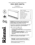
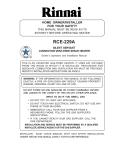
RHFE-1004FA
ENERGYSAVER
GAS DIRECT VENT WALL FURNACE
Owner’s Operation and Installation Manual
WARNING: If the information in these instructions are not
followed exactly, a fire or explosion may result causing
property damage, personal injury or loss of life.
─ Do not store or use gasoline or other flammable vapors and
liquids in the vicinity of this or any other appliance.
─ WHAT TO DO IF YOU SMELL GAS
Do not try to light any appliance.
Do not touch any electrical switch; do not use any phone in
your building.
Immediately call your gas supplier from a neighbor’s phone.
Follow the gas supplier’s instructions.
If you cannot reach your gas supplier, call the fire
department.
─ Installation and service must be performed by a qualified
installer, service agency or the gas supplier.
This appliance may be installed in an aftermarket, permanently
located, manufactured home (USA) or mobile home, where not
prohibited by local codes.
This appliance is only for use with the type of gas indicated on
the rating plate. This appliance is not convertible for use with
other gases, unless a certified kit is used.
INSTALLER: Leave this manual with the appliance.
CONSUMER: Retain this manual for future reference.
Register your product at www.rinnairegistration.com or
call 1-866-RINNAI1 (746-6241)
WARNING
IMPROPER INSTALLATION, ADJUSTMENT, ALTERATION,
SERVICE OR MAINTENANCE CAN CAUSE PROPERTY
DAMAGE, PERSONAL INJURY OR LOSS OF LIFE, REFER
TO THE OWNER'S INFORMATION MANUAL PROVIDED
WITH THIS APPLIANCE. INSTALLATION AND SERVICE
MUST BE PERFORMED BY A QUALIFIED INSTALLER,
SERVICE AGENCY OR THE GAS SUPPLIER.
ENERGYSAVER RHFE-1004FA
Operation Manual
Table of Contents
Page
FEATURES OF THE RHFE-1004FA UNITS ..........................................................1
SAFETY DEVICES ................................................................................................1
IMPORTANT POINTS / USAGE AND INSTALLATION MUSTS ............................3
DIMENSIONS ........................................................................................................5
SPECIFICATIONS .................................................................................................6
SAFETY POINTS ..................................................................................................8
GETTING TO KNOW YOUR NEW RHFE-1004FA ................................................10
CONTROL PANEL .................................................................................................11
CUT-AWAY DIAGRAM ...........................................................................................12
NOTICE BEFORE INSTALLATION .......................................................................13
INSTALLATION INSTRUCTIONS ..........................................................................14
GAS CONNECTION ..............................................................................................15
VENT TERMINATION CLEARANCES ..................................................................16
LOCATION / CLEARANCES .................................................................................17
SLEEVE AND MANIFOLD INSTALLATION ...........................................................19
FITTING UNIT .......................................................................................................21
OPERATING INSTRUCTION LABEL ....................................................................23
ADDITIONAL CUSTOMER OPERATING INFORMATION ....................................24
TESTING ...............................................................................................................30
CHECK ..................................................................................................................30
PRE-SERVICE CHECK .........................................................................................31
TROUBLE SHOOTING ..........................................................................................32
ERROR MESSAGES..............................................................................................33
MAINTENANCE / SERVICE ..................................................................................34
WIRING DIAGRAM ................................................................................................35
WARRANTY INFORMATION .................................................................................36
SCHEMATIC DIAGRAM ........................................................................................38
PARTS LIST ...........................................................................................................45
RHFE-1004FA FLOW DIAGRAM ..........................................................................50
EXTENDED FLUE PIPE KIT .................................................................................51
TECHNICAL DATA ................................................................................................56
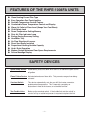
FEATURES OF THE RHFE-1004FA UNITS
◆
◆
◆
◆
◆
◆
◆
◆
◆
◆
◆
◆
◆
◆
◆
◆
Clean Heating Forced Flue Type
Easy Operation One-Touch Ignition
Sensible Temperature Control Feature
Comfortable Room Temperature Control and Display
Warm Air Outlet at Floor Level (Keeps Your Feet Warm)
Child Safety Lock
Room Temperature Setting Memory
Dirty Air Filter Indicator Lamp
Energy-Saving Economy Setting
Humidifier Tray
Air Flow Directional Louvers
Direct Vent Easily Installed
Proportional Heating Variable Capacity
Hush! Quiet Operation
Modern Design Minimizes Floor Space Requirements
Failure Message Display
SAFETY DEVICES
Spark Safety Device: Automatically shuts unit down when there is an abnormal spark at time
of ignition.
Flame Failure Device: Activated when burner flame fails. This prevents raw gas from being
released.
Overheat Switch:
This device automatically cuts the gas off if the heater exceeds a
predetermined temperature. This is normally caused by an
obstruction in front of the louvers, or a blocked fan filter.
Two Fusible Links:
Backs up the overheat switch. If the fusible link cuts the unit off, a
service call by an authorized person is required to replace the link.
–1–
Overcurrent Prevention Device: This is a 5 amp. glass fuse found on P.C. board. Design to
shut unit down in case of overcurrent. If fuse blows all
indicator lamps will be “OFF”.
Power Outage Safety Device:
This safety device cuts off gas passage and stops
operation.
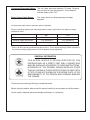
Local and state codes must be adhered to prior to installation.
Rinnai is continually updating and improving products therefore specifications are subject to change
without prior notice.
NAT.
LPG
Minimum supply gas pressure
5.0" (127mmH2O)
11.0" (279mmH2O)
Maximum supply gas pressure
10.5" (267mmH2O)
13.0" (330mmH2O)
Factory set
Factory set
Manifold test pressure
※See conversion for setting gas pressures.
*There's 1/8" NPT pipe tap provided for gas pressure test. That is located on the gas control assembly A.
The minimum inlet gas supply pressure is for the purpose of input adjustment.
GENERAL INFORMATION
THIS SERIES HEATER IS DESIGN CERTIFIED BY CSA
INTERNATIONAL AS A DIRECT VENT WALL FURNACE AND
MUST BE INSTALLED ACCORDING TO THESE INSTRUCTIONS.
ALTERATION OF THE ORIGINAL DESIGN INSTALLED OTHER
THAN AS SHOWN IN THESE INSTRUCTIONS OR USED WITH
A TYPE OF GAS NOT SHOWN ON THE RATING PLATE, IS THE
RESPONSIBILITY OF THE PERSON AND COMPANY MARKING
THE CHANGE.
Thank you for purchasing a Rinnai gas forced flue heater.
Before using this product, please read this manual carefully to insure proper use of the product.
Please read the attached warranty thoroughly and keep it in a safe place.
–2–
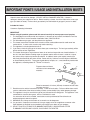
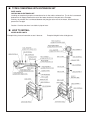
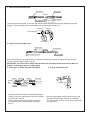
IMPORTANT POINTS / USAGE AND INSTALLATION MUSTS
Unpack heater and check for damage. (DO NOT INSTALL DAMAGED HEATER.) If heater is
damaged, contact your supplier for advice. Before installing a heater, check the label for the correct gas
type (see label on heater). Refer to local gas authority for confirmation of gas type if you are in doubt.
Included in Carton:
Customers Operating Information
IMPORTANT
Before using this product, please read this manual carefully to insure proper use of product.
1. The installation must conform with local codes or, in absence of local codes, the National Fuel Gas
Code, ANSI Z223.1 or the Canadian Installation Code, CAN/CGA-B149.
2. For information on gas type, see data plate on the appliance.
3. This heater must not be installed where curtains or other combustible materials could come into
contact with it. In some cases curtains may need restraining.
4. This appliance is not designed to be built in.
5. If you move, check the gas type in the area where you are moving to. The local gas authority will be
able to advise on local regulations.
6. This heater discharges a large volume of warm air at low level to provide even heat distribution. If
the air in the room contains cooking vapor or cigarette smoke, and the heater is used on a carpet,
the surface of the carpet may become discolored. In addition, some nylon carpets contain dyes
which may be affected by the warm air flow. Some soft vinyl surfaces are also subject to distortion,
or discoloration by warm air. To prevent discoloration of carpets, etc., a mat should be placed under
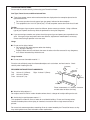
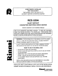
the appliance, extending about 30" (750mm) in front of it.
10"(250mm)
Diagram shows minimum
clearances from combustible
materials.
0"
2"
(50mm)
2"
(50mm)
40" (1m)
7.
8.
9.
10.
11.
Rinnai recommends 10 inches (250mm) clearance on both sides
for future servicing.
Read these rules and the instructions carefully. Check all local codes. Failure to follow these could
cause a malfunction of the heater resulting in death, serious bodily injury and/or property damage.
This appliance is only for use with the type of gas indicated on the rating plate. This appliance is not
convertible for use with other gases, unless a certified kit is used.
If a conversion of the unit is needed, conversions must be performed at Rinnai America or
anthorized agent at owner's expense.
WARNING: Any change to this heater or its controls can be dangerous.
If a gas leak is suspected, turn heater off, turn gas supply valve off at appliance connector valve.
Open windows to ventilate area immediately and contact your dealer or gas company.
DO NOT PLACE CLOTHING OR FLAMMABLE MATERIALS, GASOLINE AND OTHER
FLAMMABLE VAPORS AND LIQUIDS, ON OR NEAR THE HEATER.
–3–
12. YOUNG CHILDREN SHOULD BE CAREFULLY SUPERVISED WHEN THEY ARE IN THE SAME
ROOM WITH THE HEATER.
13. LPG containers must not be installed indoors.
14. Do not use this room heater if any part has been under water. Immediately call a qualified service
technician to inspect the room heater and to replace any part of the control system and any gas
control which has been under water.
15. Adequate clearances for accessibility for purposes of servicing and proper operation should be
provided.
16. Adequate clearances around air openings should be provided.
17. Do not install in areas where curtains, drapes, clothing, or other moving flammables are within 12
inches of this unit.
18. Periodic examination of the venting system is required.
19. The flow of combustion and ventilation air should not be obstructed.
20. A manufactured Home (Mobile Home) installation must conform with the Manufactured Home
Construction and Safety Standard, title 24CFR, Part 3280, or, when such a standard is not
applicable, the Standard for Manufactured Home Installations, ANSI A225.1 or Standard for Gas
Equipped Recreational Vehicles and Mobile Housing, CSA Z240.4.
21. "This appliance must be installed in accordance with the current standard CSA Z240.4 GAS
EQUIPPED RECREATIONAL VEHICLES AND MOBILE HOUSING. Cet appareil doit ette installe
conformement aux, exigences de la norme Z240.4 en vigeuer de l’ACNOR, Installations de gaz dans
les constructions mobiles et vehicules recreatifs."
22. If a blockage occurs at the vent terminal due to snow, ice, leaves, spider webs or other type of
obstructions the unit will stop working. The unit will not function until the blockage has been
removed. If the unit then fails to operate contact a qualified service agency.
23. For manufactured (mobile) home or residential or light commercial installation, this unit has been
designed and certified to be converted from natural gas to propane or vice-versa. When provisions
are being made to convert this unit, a certified conversion kit must be used. You must also readjust
manifold gas pressure to specifications indicated in the conversion manual. If in doubt contact
Rinnai America for assistance.
24. Clothing or other flammable material should not be placed on or near the appliance.
–4–
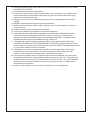
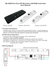
DIMENSIONS
inches (mm)
FLUE MANIFOLD POSITION
Center of hole for flue manifold can be drilled
anywhere within the shaded area. (To avoid
studs, etc.)
FOR WEATHERBOARD WALLS DRILL
THROUGH CENTER OF WEATHER BOARD
FROM OUTSIDE, THEN DRILL FROM
INSIDE THROUGH PLASTERBOARD.
3 1/8"
(80mm)
Flue Hole
14 1/16" (357.5)
Before drilling the flue hole, check for water
and gas pipes as well as electric cables. Use
a 3 1/8" (80mm) drill for hole through wall.
36 5/8" (930)
12 7/16" (316)
28 7/16" (723)
GAS CONNECTION
11 13/16" (300)
7 7/8" (200) 4 9/16" (116)
Cavity Opening
15 5/8" (397)
6 1/2" (165)
9 13/16" (250)
10 7/8"
(R277)
26 3/8" (670)
13 3/4" (R350)
13" (330)
6 5/16"(160)
–5–
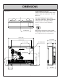
SPECIFICATIONS
BTU/h
MODEL
MIN. CLEARANCES
INPUT
OUTPUT
RHFE-1004FA-N
Low
10,500
Low
8,400
NATURAL
High
38,400
High
30,700
RHFE-1004FA-P
Low
10,500
Low
8,400
PROPANE
High
36,500
High
29,200
SIDE
TOP
FRONT
2"
(50mm)
10"
(250mm)
40"
(1m)
2"
(50mm)
10"
(250mm)
40"
(1m)
FAN CFM
OUTPUT
LO:203.4
HI:360.6
LO:203.4
HI:360.5
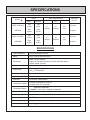
SPECIFICATIONS
Type of Appliance
Fan forced flued gas furnace
Model
RHFE-1004FA ENERGYSAVER
Dimensions
Width 36 5/8" (930mm)
Depth 12 3/8" with back spacer (315mm with back spacer)
Height 26 3/8" (670mm)
Weight
Approx. 90 lbs.
Connections
Electrical AC 120V 60Hz 121 watts
Gas 1/2" female NPT
Combustion System
Stainless steel bunsen burner
Ignition System
Continuous spark
Operation
Finger touch control buttons
Temperature Control
Electronic thermostat HI-LOW/OFF
Up/down switch 2°F increments
Temperature Range
Modulates Continuous
LOW 55°F 60°F 80°F HI High Combustion
Warm Air Outlet
Bottom front louver
Indicator/Lamps
Operation/Combustion, Filter, SetTemp., RoomTemp., Economy, Function Lock.
Operating Buttons
ON/OFF, Up/down, Function-lock, Economy
Economy Mode
Energy saving feature
Humidifier Tray
Capacity
7 pints (3000cc)
–6–
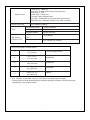
Safety Devices
Noise Level Range
TYPE
AIR SUPPLY/
EXHAUST PIPE
Flame failure – Flame rod
Over heat – Bi-metal switch, thermal fuse, thermistor
Power failure – PCB
Power surge – 5 Amp. fuse
Fan delay – Micro computer timer
Pre-purge – Combustion fan, pre-purge timer, spark sensor
Room over heat – Automatic cut off at 104°F after 10 minutes
HI
LOW
47
37dB(A)
Combustion Method
Forced combustion
Air Supply Exhaust
Closed Type
Radiation Method
Forced convection
Wall Penetration
Hole
Max. Extended
3 1/8" (80mm)
13ft., 2 bends (4m, 2 bends)
SPECIFICATIONS FOR VENT SIZES
S
3" 4 1/2"
(75 115)mm
A
4 1/2" 9 1/2"
(115 240 )mm
Wood Walls
B
9 1/2" 15 3/4"
(240 400 )mm
Wood/Brick
C
15 3/4" 23 5/8"
(400 600 )mm
Brick/Block
D
23 5/8" 31 1/2"
(600 800 )mm
Special
Thin Walls Mobile Home
** BTU - Efficiency increase with vent size. Clearances from combustibles see page 3.
** Thermal efficiency rating determined under continuous operating conditions, and was determined
independently of any installed system.
–7–
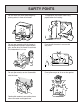
SAFETY POINTS
Do not restrict the warm air discharge by
placing articles in front of the heater.
This appliance must not be used for any
purpose other than heating.
Do not spray aerosols while the heater is
operating. Most aerosols contain butane
gas, and can be a fire hazard if used near
this heater when it is in use.
Do not install the heater in an unusually
dusty area.
Do not allow curtains or other flammable or
combustible materials to come into contact
with the heater.
Do not allow anyone to sit on or lean against
the appliance.
Combustible materials must not be placed
where the heater could ignite them.
–8–
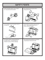
SAFETY POINTS
Keep flammable materials, trees, shrubs,
etc., away from the flue terminal.
Do not allow anyone to poke articles
through the louvers.
GAS
Gasoline
LPGAS
Filter should be cleaned at regular intervals.
See page 29.
Young children should be supervised at all
times. Hand or body contact with the
louvers should be avoided.
Clean as needed.
Do not place articles containing liquids on
top of the heater. Liquid spilled on the
controls may cause extensive damage.
Do not allow young children or an infant to
sleep directly in front of the heater.
–9–
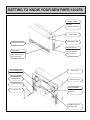
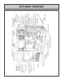
GETTING TO KNOW YOUR NEW RHFE-1004FA
CONTROL PANEL
OPERATION/TEMPE
RATURE
CONTROL DISPLAY
FILTER LAMP
OPERATION LAMP
WARM AIR OUTLET
RATING PLATE
MODEL NUMBER,
SERIAL NUMBER,
GAS TYPE, ETC.
HUMIDIFIER
OPEN THE DOOR
AND POUR WATER
INTO THE TRAY.
AIR FILTER
GAS CONNECTION
1/2" NPT
THERMISTOR
EXHAUST PIPE
POWER CORD
VENT TERMINAL
COMBUSTION/
EXHAUST
PLUG 120V AC
COMBUSTION AIR
INTAKE HOSE
– 10 –
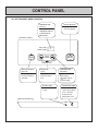
CONTROL PANEL
ALL BUTTONS BEEP WHEN OPERATED.
TEMPERATURE
DISPLAY
SHOWS EITHER THE
TEMPERATURE OR
CODED ERROR
MESSAGES.
ON/OFF BUTTON
Easy operation
One touch ignition
CONTROL PANEL
Set Temp
Room Temp
Economy
Temp
Control
ON/OFF
Function Lock
ENERGY SAVING
BUTTON
Lamp is green
when this feature is
activated.
FUNCTION
LOCK
Lamp is "green"
when this feature
is on.
FILTER LAMP
Flashes when filter
is dirty.
TEMPERATURE
BUTTONS
adjust temp. to
lower setting.
adjust temp. to
a higher setting.
OPERATION LAMP
This lamp turns
"green" when power
is on. Lamp will
change to "red"
when burner is on.
INDICATOR DISPLAY
Filter
– 11 –
ON
CUT-AWAY DIAGRAM
– 12 –
NOTICE BEFORE INSTALLATION
The heater must be installed by a qualified service
person according to these installation instruction.
The appliance, when installed, must be electrically
grounded in accordance with local codes or, in the
absence of local codes, with the National Electrical
Code, ANSI/NFPA 70 or Canadian Electrical Code,
CSA C22.1, if an external electrical source is utilized.
Check your local building codes for the proper method
of installation. In the case of absence of local codes,
this heater should be installed in accordance with the
National Fuel Gas Code ANSI Z223 1.
WARNING: THIS APPLIANCE IS EQUIPPED
WITH A THREE PRONG (GROUNDING) PLUG
FOR YOUR PROTECTION AGAINST SHOCK
HAZARD AND SHOULD BE PLUGGED DIRECTLY
INTO A PROPERLY GROUNDED THREE PRONG
RECEPTACLE.
Do not cut or remove the grounding prong from the
plug.
Check local codes or, in the absence of local codes,
the current CAN/CGA B149 INSTALLATION CODE.
DUE TO HIGH TEMPERATURES, THE
APPLIANCE SHOULD BE LOCATED OUT OF
TRAFFIC AND AWAY FROM FURNITURE AND
DRAPERIES.
CHILDREN AND ADULTS SHOULD BE ALERTED
TO THE HAZARDS OF HIGH SURFACE
TEMPERATURES AND SHOULD STAY AWAY TO
AVOID BURNS OR CLOTHING IGNITION.
Rinnai recommends a dedicated electrical circuit.
This gas appliance must not be connected to a
chimney flue serving a separate solid-fuel burning
appliance.
When the appliance is installed directly on carpeting,
tile or other combustible material other than wood
flooring, the appliance shall be installed on a metal or
wood panel extending the full width and depth of the
appliance.
“WARNING” Do not operate appliance with the
panel(s) removed, cracked or broken. Replacement
of the panel(s) should be done by a licensed or
qualified service person.
INSTALLATION AND REPAIR SHOULD BE DONE
BY A QUALIFIED SERVICE PERSON. THE
APPLIANCE SHOULD BE INSPECTED BEFORE
USE AND AT LEAST ANNUALLY BY A QUALIFIED
SERVICE PERSON. MORE FREQUENT
CLEANING MAY BE REQUIRED DUE TO
EXCESSIVE LINT FROM CARPETING, BEDDING
MATERIAL, ETC. IT IS IMPERATIVE THAT
CONTROL COMPARTMENTS, BURNERS AND
CIRCULATING AIR PASSAGEWAYS OF THE UNIT
BE KEPT CLEAN.
Appliance input ratings are based on sea level
operation and need not be changed for operation up
to 2,000 feet elevation. For operation at elevations
above 2,000 feet, manufactured to specified deration
conditions for Canada and the United States.
– 13 –
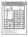
INSTALLATION INSTRUCTIONS
Spare rubber seal
...........................1
(‘A’ Flue units only)
Flue Manifold .......................1
(For weatherboard installations)
Back Spacer
Set
1
Wall
Brackets
2
Insulation
Clip
1
Plastic tie for
air inlet
1
7
(M4)
For Back Spacer Set
(M5)
4
For Wall Brackets
Air inlet hose
1
1
(M4×20)
For Flue Lock Stopper
Vent adaptor
1
3
(M4)
For Flue Manifold
Pipe stopper
A&S
Pipe stopper
E
2
(M4.8×32)
Wood Screws
1
7
Wall Bracket Screws
Owner’s Manual
Conversion Manual
Template
1
Check to ensure gas type on rating plate matches gas being supplied to the unit. If not, unit may have
been converted and should be checked to ensure conversion was done properly. If not, unit could be
damaged due to being overfired.
Refer to local gas authority for confirmation of gas type if in doubt.
Refer to data plate located inside of the front panel.
Check for damage, if the unit is damaged contact your supplier or Rinnai.
Do not install a damaged unit before checking with your supplier.
Refer to an approved pipe sizing chart if in doubt about size of gas line.
– 14 –
GAS CONNECTION
1. The gas supply line shall be gas-tight, sized and so installed as to provide a supply of gas sufficient
to meet the maximum demand of the heater without loss of pressure.
2. A shut off valve (and appliance connector valve) should be installed in the upstream of the gas line
to permit servicing.
3. Flexible pipe and any appliance connector valve used for gas piping shall be types approved by
nationally recognized agencies.
4. Any compound used on the threaded joint of the gas piping shall be a type which resists the action
of liquefied petroleum gas.
5. Supplied gas pressure must be within the limits shown in the specifications.
6. After completion of gas pipe connections, all joints including the heater must be checked for gas
tightness by means of leak detector solution, soap and water, or an equivalent nonflammable
solution, as applicable.
CAUTION: Since some leak test solutions, including soap and water, may cause corrosion or stress
cracking, the piping shall be rinsed with water after testing, unless it has been determined that the
leak test solution is noncorrosive.
7. The appliance and its appliance main gas valve must be disconnected from the gas supply piping
system during any pressure testing of that system at test pressures in excess of 1/2 P.S.I (3.5kPa).
The appliance must be isolated from the gas supply piping system by closing its individual manual
shut off valve during any pressure testing of the gas supply system at test pressures equal to or less
than 1/2 psig.
8. One 1/8" test plug is provided for testing of manifold pressure see schematic for location. (On page 43,
item # 125)
At time of installation installer must supply a 1/8" N.P.T. plugged tapping, accessible for test
manometer connection, immediately up stream of the gas supply connection to the appliance.
– 15 –
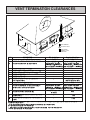
VENT TERMINATION CLEARANCES
INSIDE
CORNER DETAIL
G
H
A
I
B
D
M
FIXED
CLOSED
B
K
OPERABLE
E
B
C
J
FIXED
CLOSED
B
B
A
OPERABLE
L
V
VENT TERMINAL
X
AIR SUPPLY INLET
F
AREA WHERE
TERMINAL IS NOT
PERMITTED
B
REF
A
U.S. Installations
DESCRIPTION
1 foot
1 foot
Clearance above grade, veranda, porch, deck, or balcony
** 6 inches for appliances
B
Clearance to window or door that may be opened
Canadian Installations
10,000
Btuh, 9 inches for appliances
10,000 Btuh and
>
50,000 Btuh, 12
inches for appliances
>50,000 Btuh
6 inches for appliances
10,000 Btuh and
inches for appliances
C
Clearance to permanently closed window
*
*
Vertical clearance to ventilated to soffit, eaves, or overhang
*
*
E
Clearance to unventilated soffit , eaves, or overhang
*
*
F
Clearance to outside corner
*
*
G
Clearance to inside corner
*
H
I
*
the meter/regulator assembly
*
Clearance to service regulator vent outlet
3 feet
** 6 inches for appliances
J
Clearance to nonmechanical air supply inlet to building or
the combustion air inlet to any other appliance
L
M
Clearance to a forced air inlet into a building
>
50,000 Btuh, 12
inches for appliances
K
10,000
Btuh, 9 inches for appliances
10,000 Btuh and
>50,000 Btuh
3 feet above if within 10 feet
horizontally
Clearance above paved sidewalk or paved driveway located
on public property
Clearance under deck, veranda, porch, or balcony (open on
3 sides)
>100,000 Btuh
3 feet within a height 15 feet above
*
meter/regulator assembly
6 inches for appliances
10,000 Btuh and
inches for appliances
>100,000 Btuh
6 feet
†7 feet
*
‡1 foot
†A vent shall not terminate directly above a sidewalk or paved driveway that is located between
two single family dwellings and serves both dwellings.
Permanent only if veranda, porch, deck, or balcony is fully open on a minimum of two sides beneath the floor.
** 4 feet for units other than Direct-Vent Appliance.
– 16 –
>
100,000 Btuh, 36
*
requirement of the gas supplier.
10,000
Btuh, 12 inches for appliances
* For clearances not specified in ANSI Z223.1 / NFPA 54 or CAN/CGA-B149, use clearances in accordance with local installation codes and the
‡
>
100,000 Btuh, 36
D
Clearance to each side of center line extended above
10,000
Btuh, 12 inches for appliances
LOCATION / CLEARANCES
When positioning the heater the main points
governing the location are:
The flue terminal should be positioned away from
flammable materials.
1. Flueing
2. Warm air distribution
This heater is not designed to be built in.
LP GAS
Flue Terminal
Do not flue into natural draught flues or fireplaces,
this unit can only be used with one of the five types
of Rinnai flue kits. Do not flue unit into other rooms.
Flue terminal must be outside.
The flue is not designed to be positioned under
floors, or below the level of the heater.
Flue
Terminal
Flue
Terminal
Flue may be positioned directly under opening
windows, with a minimum clearance of 9" (230mm).
FLUE SIZES:
5 Flue lengths are available.
S flue walls 3" 4 1/2" (75 115mm)
A flue walls 4 1/2" 9 1/2" (115 240mm)
B flue walls 9 1/2" 15 3/4" (240 400mm)
C flue walls 15 3/4" 23 5/8" (400 600mm)
D flue walls 23 5/8" 31 1/2" (600 800mm)
– 17 –
SNOW AREAS
Clearance in accordance with local installation
codes and the requirements of the gas supplier.
Snow
In areas subject to heavy snowfall, keep snow clear
of flue terminal at all times.
STANDARD INSTALLATION OF FLUE MANIFOLD.
Diagram below shows minimum clearances and
distances from obstructions.
Also check local regulations.
Wall
Non
Flammable
10"(250mm)
24"
(600mm)
(600mm)24"
Flammable
20"(500mm)
Opposite
Wall
Floor
Side Clearances
20"
(500mm)
Obstruction
– 18 –
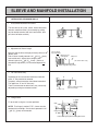
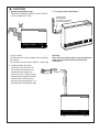
SLEEVE AND MANIFOLD INSTALLATION
METHOD FOR STANDARD WALLS
1. Disassemble Manifold from Sleeve.
The flue consists of 3 parts, sleeve, inside connectors
and tube, outside terminal; (dis-assembly by pulling
hard on outside terminal and inner connections, then
pull sleeve off outer terminal.)
Connection
Sleeve
Terminal
2. Adjustment of Sleeve Length.
Measure wall thickness through previously drilled 3 1/8
(80mm) hole.
End of sleeve should protrude 3/16" 3/8" (5 10mm)
from outside wall. Adjust sleeve length to wall
thickness plus 3/16" 3/8" (5 10mm). (Sleeve is
threaded for adjustment.) Do not extend beyond red
line.
Do not extend
beyond red line
Extension joint
under plastic
Extension
("S" and "A" flues only)
Adjust length by turning sleeve.
3. For S and A flue only.
Depending on flue set and wall thickness extension
piece “C” may need to be removed.
Cut plastic, remove extension, then follow instruction 2.
This applies to “S” and “A” flues only.
There is no extension on other flues, they can be fully
adjusted by turning the threaded section.
A
B
"A" Flue only
C
Remove extension at this
point it necessary.
4. Fixing Sleeve.
5-10mm
Fix to the wall, using the 3 screws provided.
NOTE: The flange is marked “TOP”, sleeve must be
fitted with this mark Up. Check sleeve protrudes 3/16"
3/8" (5 10mm) on the outside.
2°
"TOP"
Fixing Screw
Don't remove green plastic covering from sleeve.
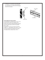
– 19 –
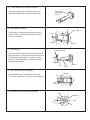
5. Check rubber seal is in place on terminal.
Terminal seal
(Add "weather board"
seal here)
*For weather board walls, add spare rubber seal
provided to compensate for weather board angle.
6. Installation of Terminal
"TOP" mark "A"
From outside, insert terminal into sleeve with the “A”
mark at the top. Left hand side fixing tie is marked
“LEFT” (from inside).
Label
Fixing tie
Terminal
7. Attached Ties
Cut (leave 20mm free)
Pull hard on left and right hand side ties, clip ties over
lugs inside sleeve. You should be able to pull ties 2 or
3 slots past the starting point. Cut the ties, leaving
about 3/4" (20mm) past the lugs. Bend ties so they
are parallel with the wall.
Pull hard
Fixing tie
Terminal
Lug
Sleeve
8. Insert Inner Connection Assembly.
Top Mark
Push assembly into the terminal tube, make sure
“TOP” mark is uppermost. Fix with 3 screws provided.
Screw
lnner
Connections
9. Manifold can still be turned after attaching.
Outlet
20˚
Rubber cap
Inlet
– 20 –
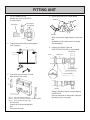
FITTING UNIT
1. Fix Flue Adapter to Flue
Manifold with PIPE STOPPER S
as shown below.
4. Secure with plastic tie as shown below.
Plastic tie
Pipe stopper S
Flue Adapter
Flue Manifold
Inlet elbow
Inlet hose
When servicing unit replace plastic tie with new
one.
(Available at local hardware store or contact
local distrilbutor.)
2. Fit Wall with wall bracket as shown below.
(Use Template.)
5. Connect Vent Sliding Tube with
PIPE STOPPER S and E as shown beIow.
723
30
Flue Manifold
24
Wall bracket
606
Screw
Sliding Tube
PIPE STOPPER S
PIPE STOPPER A
PIPE STOPPER E
3. Fit Air inlet Hose to heater. Fix Side
Back Spacers with screws.
FILT
ER
FILT
ER
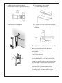
Red line
B
Flexible Plactic Hose (C)
Sliding Tube should not be extended beyond
the RED LINE.
Red line should not be visible after sliding the
tube back into the vent outlet.
A
FLU
EM
AN
IFO
LD
Pipe “A” - Swivels for location adjustment
Pipe “B” - Telescopic-telescopes into pipe A and flue manifold
Pipe “C” - Fits on manifold “Air Intake” pipe
Air lnlet Hose
Connect Air Inlet Hose to Manifold
lnlet.
Do not kink the hose.
– 21 –
6. Slide the insulation sleeve up to the flue
manifold,slip the securing clip over the sleeve as
shown.
8. Fix Back Spacer, Top to heater.
(3 screws in top back cover).
7. Fit Wall bracket as shown below.
9. If necessary, the unit can be levelled using the
adjustable legs under the front right and left hand
side legs.
Up to
3/8"(10mm)
SCREW
(M5)
Adjustable Leg
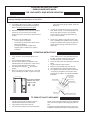
■ INSTRUCT CUSTOMER ON USE OF HEATER
When you are satisfied that the appliance is
operating correctly, explain operation of heater to
the customer.
Fault-Failure Procedure
SCREW
(M5)
If unable to get the heater to operate correctly,
contact Rinnai directly or your Agent or Gas Utility.
Do not use electrical extension cords to connect unit
to power supply. Keep the power cord away from
the flue.
Some items are not covered under the unit’s
warranty. Example: annual maintenance, carbon on
flame rods/igniter, dust, spider webs, improper
conversions, etc.
– 22 –
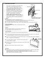
OPERATING INSTRUCTION LABEL
ENERGYSAVER RHFE-1004FA
FOR YOUR SAFETY READ BEFORE OPERATING
WARNING: If you do not follow these instructions exactly, a fire or explosion may result causing
property damage, personal injury or loss of life.
A.
This appliance does not have a pilot. It is equipped
with an ignition device which automatically lights the
burner. Do not try to light the burner by hand.
B.
BEFORE OPERATING smell all around the appliance
area for gas. Be sure to smell next to the floor
because some gas is heavier than air and will settle on
the floor.
•
WHAT TO DO IF YOU SMELL GAS
•
Do not try to light any appliance.
•
Do not touch any electric switch; do not use any
phone in your building.
•
Immediately call your gas supplier from a
neighbor's phone. Follow the gas supplier's
instructions.
If you cannot reach your gas supplier, call the fire
department.
C.
Use only your hand to push in or turn the gas control
knob. Never use tools. If the knob will not push in or
turn by hand, don't try to repair it, call a qualified
service technician. Force or attempted repair may
result in a fire or explosion.
D.
Do not use this appliance if any part has been under
water. Immediately call a qualified service technician
to inspect the appliance and to replace any part of the
control system and any gas control which has been
under water.
OPERATING INSTRUCTIONS
•
1.
2.
3.
4.
STOP! Follow “B” in the safety information above on
this label. If you don't smell gas go to next step.
5. Turn Manual gas valve to the full on position.
6. Turn on all electric power to the appliance via ON/OFF
button.
7. Set the thermostat to desired setting.
8. Burner is lit when indicator lamp “ON” turns red.
9. “ON” indicator flashes when burner fails to ignite.
10. If the appliance will not operate, follow the instruction
“TO turn off gas to appliance” and call your service
technician or gas supplier. See manual for additional
information.
Temperature Button
STOP! Read the safety information above on this
label.
Set the thermostat to lowest setting.
Turn off all electric power to the appliance via the
ON/OFF button on the control panel. Locate manual
gas valve to be found on back side of heater.
Turn Manual valve clockwise
to the full OFF
position.
Wait five (5) minutes to clear out any gas. Then smell
for gas, including near the floor. If you then smell gas,
LED Display
BACK SIDE OF HEATER
MANUAL GAS VALVE
OPEN CLOSED
Economy Button
ON/OFF Button
Filter Lamp
Operation/Combustion Lamp
TO TURN OFF GAS TO APPLIANCE
1.
2.
3.
Turn off electric power to the appliance using the
ON/OFF button located on the control panel.
Locate manual valve on back side of unit.
Turn manual valve clockwise to the full OFF position.
NOTE: The fan will continue to operate until the appliance is
cool, do not turn the appliance off by unplugging it from the
wall.
Keep burner and control compartment clean. Refer to the
installation and operating instructions accompanying heater.
– 23 –
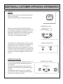
ADDITIONAL CUSTOMER OPERATING INFORMATION
IGNITION
Make certain the heater is connected into both the gas
and the electric power.
Depress the ignition ON/OFF button slowly and firmly.
ON/OFF
TEMPERATURE LEVEL
When you release the ignition ON/OFF button the
‘LED Display will illuminate, the spark will ignite the main
burner and the Combustion fan will begin to run. If the
heater does not ignite within 15 seconds the spark will
stop and the ‘LED Display will show Error Code.
Turn off unit and repeat ignition operation.
Set Temp
Room Temp
Temp
Control
Function Lock
COMBUSTION INDICATOR
This heater has an automatic ignition system, when the
main burner has lit, the combustion Lamp will glow red,
and the spark will stop. There may be a smell of
burning dust or oil the first time the heater is lit or when
the heater has been out of operation for a long time, this
is normal.You may need to repeat the ignition operation
the first time the heater is plugged in, due to air in the
gas line.
Filter
ON
TEMPERATURE CONTROL
The thermostat automatically modulates the burner and
the fan to maintain the room temperature which you
have selected.
To change the room temperature, simply adjust the
temperature control buttons until the desired setting is
indicated.
The temperature range from LO to HI is about 55°F
(12°C) to 122°F (50°C). Temperature control may be
affected by the location of the heater.
– 24 –
TEMPERATURE CONTROL
Set Temp
Room Temp
Economy
Temp
Control
Function Lock
ON/OFF
ROOM TEMPERATURE DISPLAY
‘Temperature is indicated by the L.E.D. display on the control
panel. The first time when the appliance is turned on, the preset
temperature ’72 F degrees’(from the factory) will be shown on
the L.E.D.dispIay. Every time the Set Temp has been
changed,that set temperature will be latest data appearing on
the L.E.D. display on the next time the appliance is turned on.
To get to Set Temp,press either ‘ up ’ or ‘ down ’ button. At the
Set Temp, press ‘ up ’ to increase the temperature or ‘ down ’ to
decrease. When the desired temperature is set, 10 seconds
later the LED display will change to the room temperature mode
which will show the current room temperature.
Set Temp
Room Temp
Temp
Control
Function Lock
IGNITION BUTTON
TO TURN UNIT OFF
Depress ignition ON/OFF button again.
The appliance will stop operate.
Do not turn off by unplugging at the power outlet.
Convection fan continues to run until heater is cool.
ON/OFF
ECONOMY BUTTON
To select ‘Economy Mode’, push the ‘Economy’ button,
the green lamp will glow. 30 minutes after the room
temperature reaches the preset temperature (set by the
thermostat), the ‘Economy Mode’ if set, reduces the
temperature by 2°F, after another 30 minutes it reduces
the temperature by a further 2°F. This is an energy
saving feature. It does not operate if the heater is under
capacity for the room size.
ECONOMY
T
Co
Economy
Funct
FILTER LAMP
If the filter lamp glows during operation, check air filter
for dust. If there is dust present, clean filter. See
section on care of heater. Turn heater off before
cleaning filters.
– 25 –
Filter
ON
OPERATING PRECAUTIONS
Please read this section carefully, before using your Forced flue heater.
Gas Type, Power Source, and Manufactured Date
■ Type of gas, power source and manufactured date are displayed on the nameplate placed on the
right side of the unit.
Do not use gas other than the type of gas (gas group) indicated on the nameplate.
This equipment is for 120 V AC (60Hz) only. Do not use power source other than what is listed.
Caution
● Should the type of gas or power source be different, please contact your dealer. Using a different
type of gas or power source may affect the performance or may be dangerous.
● If you are moving to another area, please check the types of gas and power source provided in the
area. If the types of gas and power source are different, adjustment or modification is necessary.
Please consult the gas provider in the new area.
Usage
■ Do not use for drying clothes!
Do not use for any other purposes other than heating
(e.g., drying the laundry).
Draping clothes over the unit blocks the warm air outlet or the filter area and is very dangerous,
as it causes heat to build up inside the unit.
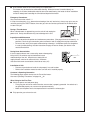
Usage Location
■ Do not use near flammable material ! ! !
Place the unit sufficiently away from flammable objects such as furniture, wall and curtains. Check
carefully when installing the unit.
10"(250mm)
0"
REQUIRED DISTANCE FROM FLAMMABLES:
Top:
At least 10" (250mm)
Left:
At least 2" (50mm)
Front: At least 40" (1m)
Right: At least 2" (50mm)
2"
(50mm)
2"
(50mm)
40" (1m)
Rinnai recommends 10" (250mm) clearance
on both sides for future servicing.
■ Watch for falling objects ! ! !
Do not place under a shelf or in other locations where there is a danger of an object falling on the unit.
■ Avoid using in special purpose rooms ! ! !
This equipment is made for use as a heater for a residential building. Do not use in beauty salons,
factories and other places where spray or chemicals are used or where a large amount of dust is
present.
Do not use hair treatment products containing silicon in a room heated by the Forced flue heater, as they
may cause ignition error, flame extinction or other malfunctions.
– 26 –
■ Insert a board under the unit when placing on carpeted floor ! ! !
This heater may be installed on combustible flooring. When the heater is installed directly on
carpeting, tile or other combustible material other than wood flooring, the heater shall be installed on
a metal or wood panel extending the full width and depth of the heater.
Emergency Procedures:
Stay calm and turn the unit off ! ! !
In case of an emergency (e.g., abnormal overheating of the unit, loud noise), always stay calm, turn the
unit off by pushing the ON/OFF button, close the gas valve and contact your dealer or the Rinnai office
or store near you.
During a Thunderstorm
When a thunderstorm is approaching, turn the unit off and unplug the
power cord. Heavy thunderstorm may cause damage to the unit.
Inspection and Maintenance
• Be sure to perform inspection and maintenance procedures. (See page 29 and 34 for details.) In
particular, check the gas connection, power connection and air supply/exhaust pipe connection.
• Do not use the unit if you suspect malfunctioning or damage. Incomplete repairs are dangerous.
In case of malfunctioning, read the instructions on page 32 and or contact your dealer or the
nearest Rinnai office.
During Snow Accumulation
If the air supply/exhaust vent is covered by snow or damaged by
falling icicles, the exhaust may be blocked and cause
malfunctioning of the unit. Keep the area around the air
supply/exhaust vent free of snow and icicles. Minimum
clearance from snow accumulations should be at least (24").
snow
24"
Installation of Unit:
• Please ask your dealer to install the unit properly in a safe location:
• Refer to the installation manual to make sure the unit is installed properly.
Customer's Operating Information
The following pages explain how to use the Forced flue heater.
Also read “Operating Precautions” on pages 23 26.
When Using for the First Time
■ Check the power cord and power plug.
• Firmly plug the unit into an electrical outlet, ensure outlet is properly grounded. An outlet that is
not grounded properly can cause unit to operate erratically.
• Make sure the power cord is not exposed to the heat from the exhaust pipe.
■ Fully open the gas valve on the unit.
– 27 –
Before the Cold Season Begins
■ Check the air supply/exhaust connection.
● Before using this heater, inspect the air supply/exhaust connection to make sure the pipe is not
disconnected or bent.
■ Check the main unit and the air supply/exhaust.
● Make sure there is no combustible or flammable material near the main unit or the air
supply/exhaust.
CAUTION:
If you find a problem with the air supply/exhaust do not use the unit. Contact your dealer or the nearest
Rinnai office.
Function Lock
The Function lock feature prevents accidents due to tampering by small children.
■ Press both“ ” and “ ” button at the same time.
The “Function Lock” lamp should comes on and engage the function lock.
■ Cancelling the Function lock.
Press both“ ” and “ ” button again and hold for two (2) seconds.
This will disengage the function lock.
Note:
If the Function lock is engaged while the unit is operating, all operations by switches and buttons will be
disabled except turning the unit off.
If the Function lock is engaged while the unit is off, all operation will be disabled. When you turn the unit
on and the Function lock is engaged you must cancel the Function lock before preceding.
AIR FLOW CONTROL:
■ The direction of air flow may be changed to the
left or right.
Use a screwdriver or a similar object to change
the direction of the vertical
louver.
CAUTION:
● Do not adjust repeatedly (more than 5 6 times), as it
may cause the louver to break.
● The horizontal louver (which determines the vertical
air flow direction) is fixed and cannot be adjusted.
● Do not adjust the air flow direction while warm air is
flowing, as it may cause burn injury.
Sensible Temperature Control:
The sensible temperature control feature enables comfortable heating which matches the conditions in
the room.
• Based on the information collected by the room temperature thermistor when the heating starts,
the heating capacity is automatically adjusted to achieve a comfortable heating effect and to
reach the set room temperature quickly.
– 28 –
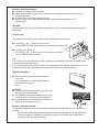
Adding Water to Humidifier:
Humidifier Tray
So that you can humidify the air your RHFE-UNIT
Max. Fill Line
is fitted with an enamelled tray behind the air
outlet. To fill the tray, open the door as shown
in the diagram and pour water into the tray using
the spout built into the door. The air will be
humidified as it passes over the water in the tray.
Access Door
DO NOT FILL THE TRAY WHILE THE UNIT IS
IN OPERATION. CLOSE THE DOOR AFTER
FILLING. The RHFE UNIT is a very high
Pull
efficiency appliance,during operation a small
amount of water is produced in the vent tubes,this
drains into the enamel tray. It is quite normal for a
small quantity of water to remain in the bottom of
Filler Spout
Do not force door open too far.
the tray.
Close door during operation.
Caution:
● The humidifier tray and the surrounding area are
hot when the unit is on. To avoid burns, do not add water to the tray while unit is on.
● Avoid adding water when the room is susceptible to condensation.
● If the water overflows from the water level hole when adding water, do not add any more water.
Care of Unit Exterior:
Dampen soft cloth with warm water, wring water out well and
wipe the unit.
Caution:
Never use volatile substances such as benzine or thinners, as
they cause fading of paint or deformation of resin.
Care of Air Filter:
Always clean the air filter when the filter indicator lamp starts blinking.
■ The filter indicator lamp starts blinking when the dust accumulates on the air filter. In this event, turn
the unit off immediately, wait until the unit cools off and clean the filter.
■ Even if the lamp is not blinking, if you think the filter is dirty, clean the filter while you are cleaning the
room. This will ensure comfortable use.
AIR FILTERS
■ The air filter may be removed. Clean both sides of the filter with a
vacuum cleaner or a duster.
■ If the filter is greasy, wash quickly with detergent, shake water off and
dry completely.
■ After cleaning and drying, replace the filter securely.
CAUTION:
● If you continue to use the heater with the filter indicator lamp flashing, the sensor may detect trouble
and turn the unit off. Causing the room temperature display lamp "14" and the
"operation/combustion" lamp to flash , indicating that the safety device has been activated. In this
event, clean the air filter immediately as above.
– 29 –
TESTING
CHECK
Testing Unit
Fault-Failure Procedure
Purge air from gas line.
Refer to pipe sizing chart if in doubt about the size of
the gas line.
Connection can easily be reached from the top, rear
of the unit. Check for leaks, using soapy water after
turning gas on.
If unable to get the unit to operate correctly, contact
Rinnai Agent, or Gas Utility. Please read the fault
finding charts before reporting faults.
Do not use this heater if any part has been under
water. Immediately call a qualified service
technician to inspect the heater and to replace any
part of the control system and any gas control which
has been under water.
Plug unit in and turn power on, (CAUTION 120V
inside unit).
Turn thermostat to “HI”, turn control to “ON”. Unit
should ignite within 10 seconds.
If unit does not ignite, there may be air in the gas
line, turn control “OFF” then “ON” again.
Check pressure, regulator is factory set, if pressure
is incorrect, check supply before altering regulator.
The appliance must be stopped before testing unit.
Remove the test point screw and connect
manometer to pressure point on the modulating
valve.
Turn the unit to “ON” position using the ON/OFF
button on the operation panel and check pressure.
If pressures are correct remove manometer and
replace test point plug.
Leak test all gas connections.
“WARNING” Do not operate appliance with the
panel(s) removed, cracked or broken.
Installation and repair it should be done by a
qualified service person. The appliance should be
inspected before use and at least annually by a
qualified service person.
More frequent cleaning may be required due to
excessive lint from carpeting, bedding material, etc..
It is imperative that control compartments, burners
and circulating air passageways of the appliance be
kept clean. Ventilating system should be inspected
and cleaned annually of all debris and spider webs.
Rinnai's service assistance telephone number is
1/800/621 9419.
WARNING: DO NOT OPERATE UNIT UNTIL PROPER INSTALLATION HAS BEEN COMPLETED.
– 30 –
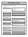
PRE-SERVICE CHECK
Before asking for a service call please check the following points.
These points are part of the normal operation of the unit.
■ At Ignition:
Heater does not operate.
Is the heater plugged in?
Have the fuses or breaker blown at the switch board?
Is there a power failure?
Is the air filter blocked?
Is anything blocking the outlet for the hot air?
Is the flue blocked?
Warm air does not flow when the burner
lights.
The fan is started automatically after a short delay.
This is to allow the heat exchanger to warm up, helping to avoid cold draughts.
Smoke or strange smells are produced
on the first trial light up after installation.
This is caused by grease or oil and dust on the heat exchanger and will stop
after a short time.
Sharp clicking noises at ignition, or when
unit cuts down on the thermostat, or goes
out.
This is simply expansion noise from the heat exchanger.
■ During Combustion:
Clunking noise when the thermostat
operates.
This is the sound of the solenoid gas valves opening and closing.
Unit is not heating room.
Is the air filter blocked?
Is the set temperature high enough?
Is the warm air outlet blocked by anything?
Are the doors and windows of the room closed?
Air filter is blocked or the louvers are
blocked or obstructed.
Allow heater to cool, clean air filter, operate again.
Heater will not re-ignite after overheating.
Even after unit has cooled down the heater does not ignite again. Repair is
necessary.
Contact your local agent or Rinnai for a Service call.
■ When the unit is turned off.
Convection fan continues to run after
turning OFF.
This is to remove the residual heat from the heat exchanger, the fan will stop
when the heater cools down.
■ Other Points:
Steam is discharged from the flue terminal.
High efficiency appliances tend to discharge water vapor on cold days, this is
normal.
Unit cuts off without apparent reason.
Check whether filters are blocked, dirty filters will cause the heater to overheat.
Power Failure.
Switch OFF, then ON again when power is restored to re-set controls.
– 31 –
TROUBLE SHOOTING
Takes too long to
warm the room
Noisy ignition
Smell of gas
Combustion stops
during operation
Unusual combustion
Cause
No ON indicator
Problem
Burner doesn't ignite
Your RHFE-1004FA requires very little maintenance, simply clean the rear fan filter as needed and wipe
the outer case and louver section with a damp cloth.
Remedy
Not Plugged In
Plug In
Power Cut
Re-ignite manually after
power is restored
(Initial Installation)
Air In Gas Pipe
Purge air
(Installer)
Gas Filter Blocked
Service Call
Miss Ignition
Service Call
Flue terminal obstructed
Clear obstruction
Flue manifold not connected
Service Call
Louver obstructed
Clear obstruction
Air filter blocked
Clean filter
Gas Escape
Service Call
Function Lock Set
Cancel Function Lock
Gas turned off at meter
Turn gas on
General maintenance items are not covered under unit's warranty. Such as cleaning dust, debris and
carbon from flame rod, spider webs, and improper set up of unit.
– 32 –
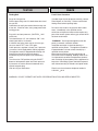
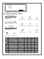
ERROR MESSAGES
The Energysaver 1004 has the ability to check its own operation continuously. If a fault occurs, an Error Message
will flash on the Digital Display of the control panel. This assists with diagnosing the fault, and may enable you to
overcome a problem without a service call. Please quote the code displayed when inquiring about service.
CODE DISPLAYED
FAULT
REMEDY
11
Ignition failure
Check gas is turned ON.
Service call if repeated.
12
Flame failure
Check gas is turned ON.
Service call if repeated.
14
Overheat
Clean filter
Service call if repeated.
16
Room overheat
Lower room temperature
to less than 40°C(104°F).
Room Temperature
Sensor faulty
Service call.
Overheat Temperature
Sensor faulty
Service call.
53
Sparker failure
Service call.
61
Combustion fan failure
Service call.
70
Faulty ON/OFF switch
Service call.
71
Faulty solenoids
Service call.
72
Faulty Flame Rod
Service call.
73
Communication Error
Turn heater OFF,
then ON again.
49
Sensor breakdown
31
32
33
34
99
Flue block
Service Call.
Check around flue terminal
In all cases, you may be able to clear the Error Message simply by turning the heater OFF, then ON again.
If the Error Message still remains or returns on the next operation, contact Rinnai or your nearest service
agent and arrange for a service call.
– 33 –
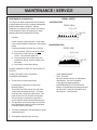
MAINTENANCE / SERVICE
MAINTENANCE SUGGESTIONS
This heater has been designed and constructed for
a long performance life when installed and operated
properly under normal conditions. Regular
inspections, as outlined in this section, are strongly
recommended as means of keeping your heater
operating efficiently throughout the season.
VISUAL CHECK
SATISFACTORY
FRONT VIEW
1. Cleaning
Heater must be cleaned annually. Keep heater
clear of dust and debris especially in and around
burner.
Cleaning procedures of heater are as follows:
UNSATISFACTORY
FRONT VIEW
1) Turn heater off. Allow to cool for one hour.
2) Remove the Front Panel by removing
screws. See schematic page 38.
3) Use pressurized air to remove dust from
around main burner, heat exchangers and
fan blades.
4) Use soft dry cloth to wipe cabinet.
DO NOT DAMAGE OR DISTORT ANY PARTS OF
HEATER.
•
•
DO NOT USE WET CLOTH OR SPRAY
CLEANERS ON BURNER.
2. Visual check of main burner flames.
Flame pattern should be as shown in the
following Figures.
The burner must flame evenly over the entire
surface when operating correctly. The flame
must burn with a clear blue stable flame. See
page 40 item # 417 for location of view ports.
Any and all parts removed for inspection or
service must be replaced before operating unit.
3. The appliance area must be kept clear and free
from combustible materials, gasoline and other
flammable vapors and liquids.
•
4. The flow of combustion and ventilation air should
not be obstructed.
5. Verify proper operation after servicing.
– 34 –
VENT MAINTENANCE
VENT SYSTEM
Must be checked annually for blockage or
deterioration. See vent installation
instructions for proper assembly.
MAINTENANCE ELECTRIC MOTORS
Motors are permanently lubricated and need
no lubrication. Keep fan and motor free of
dust and dirt. Clean annually.
– 35 –
PARTS NAME
MAIN SWITCH
THERMISTOR
THERMAL FUSE
FUSE
ELECTRODE
MODULATING SOLENOID VALVE
TRANSFORMER
FLAME ROD 1∼3
MARK
OH.TH
OHS
FM
SP
SV1∼3
BL
PS
PARTS NAME
OVER HEAT THERMISTOR
OVER HEAT SWITCH
CONVECTION FAN MOTOR
SPARKER
MAIN SOLENOID VALVE 1∼3
COMBUSTION FAN MOTOR
PRESSURE SENSOR
If any of the original wire as supplied with the appliance must be
replaced, it must be replaced with a wire of a least a 194°F
temperature rating and number 18AWG or its equivalent.
“CAUTION: Label all wires prior to disconnection when servicing
controls. Wiring errors can cause improper and dangerous operation.”
Verify operation after servicing
MARK
MS
R.TH
TF1∼3
F
ER
POV
TR
FR1∼3
CONSUMER SUPPORT
Warranty Information
The installer is responsible for your heater’s correct installation.
Please complete the information below to keep for your records:
Purchased from:
Address:
Phone:
Date of Purchase:
Model No.:
Serial No.:
Installed by:
Installer’s License No.:
Address:
Phone:
Date of Installation:
Limited Warranty
Gas Direct Vent Wall Furnace
What is covered?
This Warranty covers any defects in materials or workmanship, subject to the terms stated below. This Warranty
extends to the original purchaser and subsequent transferees, but only while the product remains at the site of
the original installation. This Warranty only extends through the first installation of the product and terminates if
the product is moved or reinstalled at a new location.
How long does coverage last?
Item
Period of Coverage
Heat Exchanger
10 years from date of purchase *
All Other Parts
5 years from date of purchase
Reasonable Labor
2 years from date of purchase
– 36 –
Limited Warranty - continued
What will Rinnai do?
Rinnai will repair any part or component that is defective in materials or workmanship as set forth as follows. All
repair parts must be genuine Rinnai parts. All repairs or replacements must be performed by an individual or
servicing company that has been authorized by Rinnai. Rinnai will pay reasonable labor charges associated
with the repair or replacement of any part or component.
Replacement of the product may be authorized by Rinnai only. Rinnai does not authorize any person or
company to assume for it any obligation or liability in connection with the replacement of a product. If Rinnai
determines that repair of a product is not possible, Rinnai will replace the product with a comparable product, at
Rinnai’s discretion.
* If the Heat Exchanger fails due to a defect in
material or workmanship within the sixth (6)
through the tenth (10) year from the date of
purchase, Rinnai will make the following
allowances toward the purchase of a
replacement Heat Exchanger:
Heat Exchanger
Year of Failure
Allowance
6
50%
7
40%
8
30%
9
20%
10
10%
How do I get service?
You must contact a qualified/authorized service provider for the repair of a product under this Warranty. For the
name of a qualified/authorized service provider please contact your place of purchase, visit the Rinnai website
(www.rinnai.us), call Rinnai at 1-800-621-9419 or write to Rinnai at 103 International Drive, Peachtree City,
Georgia 30269.
Proof of purchase is required to obtain warranty service. You may show proof of purchase with a dated sales
receipt, or by registering within 30 days of purchasing the product. To register your appliance, please visit
www.rinnairegistration.com. For those without internet access, please call 1-866-RINNAI1 (746-6241).
Receipt of Registration by Rinnai will constitute proof-of-purchase for this product. However, Registration is
not necessary in order to validate this Warranty.
What is not covered?
This Warranty does not cover any failures or operating difficulties due to accident, abuse, misuse, alteration,
misapplication, force majeure, improper installation, improper conversion*, improper maintenance or service, or
for any other causes other than defects in materials or workmanship. This Warranty does not apply to any
product whose serial number or manufacture date has been defaced.
* Improper conversion includes conversions for inventory adjustment.
Rinnai is not liable for any special, incidental, indirect or consequential damages that may arise, including
damage to person or property, loss of use, or inconvenience. Some states do not allow the exclusion or
limitation of incidental or consequential damages, so the above limitation may not apply to you.
Limitation on implied warranties
Any implied warranties of merchantability and fitness arising under state law are limited in duration to the period
of coverage provided by this limited Warranty, unless the period provided by state law is less. Some states do
not allow limitations on how long an implied Warranty lasts, so the above limitation may not apply to you.
This Warranty gives you specific legal rights, and you may also have other rights which vary from state to state.
– 37 –
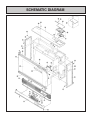
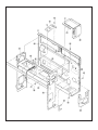
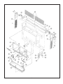
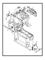
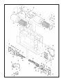
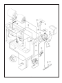
SCHEMATIC DIAGRAM
– 38 –
– 39 –
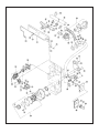
– 40 –
147
926
924
149
148
146
145
150
145
146
924
925
152
144
904
137
139
140
138
141
107
151
109
901
910
110
111
140 139
901
141
143
142
910 712
909
712
431
909
432
– 41 –
– 42 –
– 43 –
– 44 –
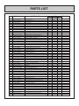
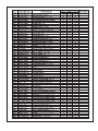
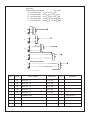
PARTS LIST
No.
001
002
003
004
005
006
007
008
009
010
011
012
013
014
015
016
017
018
019
020
021
022
024
025
026
027
100
101
DRAWING No.
1001F-073
1001F-073-4
1001F-073-5
1004F-2071
1004F-2071-3
1004F-2071-4
1004F-2073-2
1004F-2073-6
1004F-2073-8
556F-558-2
ZUAA02SZ
1001F-1514-2
1001F-1514-3
1001F-1514-4
1001F-160-2
1001F-160-5
1001F-160-6
1004F-2080
1004F-2087
1004F-2086
1001F-084-2
1001F-084-3
1001F-084-4
1001F-163-2
1001F-1323
1001F-163-3
1001F-162
1001F-162-4
1001F-162-5
1001F-164-4
1001F-1322
1001F-164-6
1001F-078
551F-015
RHF300-185-1
1001F-1410-2
1001F-1410-9
1001F-1410-10
1001F-1411-1
1001F-1411-2
1001F-1411-3
1001F-166-4
1001F-166-8
1001F-166-9
1001F-165-10
1001F-165-13
1001F-165-14
1004F-228
1001F-092
1004F-825
1001F-157
550F-0220
550F-0225
1004F-2111
1001F-150-3
1001F-144-3
PART NAME
SIDE PANEL
SIDE PANEL D
SIDE PANEL E
TOP PLATE
TOP PLATE C
TOP PLATE D
OPERATION LID B
OPERATION LID F
OPERATION LID H
FULCRUM
STOPPER
DECORATION PANEL ASS’Y C
DECORATION PANEL ASS’Y D
DECORATION PANEL ASS’Y E
FRONT PANEL ASS’Y B
FRONT PANEL ASS’Y E
FRONT PANEL ASS’Y F
ESCUTCHEON PANEL
ESCUTCHEON PANEL B
ESCUTCHEON PANEL C
LOUVER SUPPORT TRIM B
LOUVER SUPPORT TRIM C
LOUVER SUPPORT TRIM D
LOUVER ASS’Y B
LOUVER ASS’Y
LOUVER ASS’Y C
BOTTOM TRIM ASS’Y
BOTTOM TRIM ASS’Y D
BOTTOM TRIM ASS’Y E
FILLER ASS’Y D
FILLER ASS’Y
FILLER ASS’Y F
LOUVER DOOR HINGES
FILLER
MAGNET
BACK SPACER LEFT A
BACK SPACER LEFT E
BACK SPACER LEFT F
BACK SPACER B RIGHT A
BACK SPACER B RIGHT B
BACK SPACER B RIGHT C
OPERATION LID D
OPERATION LID H
OPERATION LID I
BACK SPACER UPPER ASS’Y J
BACK SPACER UPPER ASS’Y M
BACK SPACER UPPER ASS’Y N
AIR FILTER ASS’Y
BACK SPACER SUPPORT
WALL BRACKET B
LEG ASS’Y
RUBBER BRACKET ASS’Y
BASE SUPPORT RUBBER
Lamp house
HIGH BURNER LEFT ASS’Y C
HIGH BURNER RIGHT ASS’Y C
– 45 –
QTY
REMARKS
1004FA 1004FA-W 1004FA-S
2
2
2
1
1
1
1
1
1
1
1
1
1
1
1
1
1
1
1
1
1
1
1
1
1
1
1
1
1
1
1
1
1
1
1
1
1
1
1
1
1
1
1
1
1
1
1
1
1
1
1
1
1
1
1
1
2
2
2
2
2
4
1
1
1
2
2
2
2
2
4
1
1
1
1
2
2
2
2
2
4
1
1
1
’
’
’
’
’
’
’
’
’
’
’
’
’
’
’
’
’
’
– 46 –
’
’
’
’
’
’
’
’
’
’
’
’
’
’
’
’
’
’
’
– 47 –
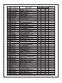
No.
713
714
800
800
801
801
802
803
804
805
806
806
807
808
809
810
810
811
812
813
813
814
814
850
851
852
853
853
854
855
901
902
903
904
905
906
907
908
909
910
911
912
913
914
915
916
917
918
919
920
921
922
923
924
925
926
927
DRAWING No.
1004F-2058
1004F-2061
CP-74167-13
CP-74167-14
CP-74168-13
CP-74168-14
1004F-2093
1001F-1651
556F-2065
1001F-1656
431F-1840
431F-1841
1001F-1654
CP-7206B-2
431F-1860
431F-1862
431F-1863
431F-1830
CP-71747-2
CP-74253-9
CP-74253-10
CP-74254-9
CP-74254-10
1004F-2090
1004F-2092
1004F-2091
1004F-2095-1
1004F-2095-2
FOT-106-6
FOT-187
FOT-187-2
FOT-187-3
ZBA0408SC
ZBA0408SZ
CP-30421-1
ZBA0412SZ
ZBB0410SC
ZBD0408SC
ZBD0408SZ
ZEAB0408SZ
ZEAB0408SB
ZEAB0408SC
ZGAA0308SZ
ZAA0506SZ
ZAA0420SZ
ZEDB0408SZ
ZHAA0408SZ
ZHAD0510SC
ZDAA0410SZ
ZIAD0408SZ
ZRAB04SZ
ZSCA04SZ
CP-30408
ZAA0306SZ
CP-30486-2
ZSCA04SC
ZRAA04SC
ZAA0440UK
ZIAD0410SC
PART NAME
SV.IG LEAD ASS’Y
TF LEAD ASS’Y
RATING PLATE
RATING PLATE
RATING PLATE
RATING PLATE
OPERATION LABEL
FILTER LABEL
CAUTION LABEL
CAUTION MARK
PROPANE STICKER
NG STICKER
EXHAUST CAUTION LABEL
SPEC MARK
POWER SUPPLY CABLE LABEL
GAS CHECK LABEL
GAS CHECK LABEL
EXHAUST CAUTION LABEL
PULL LABEL
RATING PLATE SUPPORT LABEL
RATING PLATE SUPPORT LABEL
RATING PLATE SUPPORT LABEL
RATING PLATE SUPPORT LABEL
OWNER’S MANUAL
CONVERSION MANUAL
TEMPLATE
CONVERSION SET(TO NG)
CONVERSION SET(TO LPG)
KEY
OPERATION LID SET
QTY
REMARKS
1004FA 1004FA-W 1004FA-S
1
1
1
1
1
1
1
1
1
1
1
1
1
1
1
1
1
1
1
1
1
1
1
1
1
1
1
1
1
1
1
1
1
1
1
1
1
1
1
1
1
1
1
1
1
1
1
1
1
1
1
1
1
1
1
1
1
1
1
1
1
1
1
1
1
1
1
1
1
1
1
1
1
1
1
1
1
1
1
1
1
1
1
1
1
1
1
1
1
1
SCREW
SCREW
SCREW
SCREW
SCREW
SCREW
SCREW
SCREW
SCREW
SCREW
SCREW
SCREW
SCREW
SCREW
SCREW
SCREW
SCREW
SCREW
NUT
WASHER
SCREW
SCREW
SCREW
WASHER
NUT
SCREW
SCREW
– 48 –
Vent sizes:
5 Vent lengths are available.
inch (mm)
S Vent suits walls 3" 4 1/2" (75 115)
A Vent suits walls 4 1/2" 9 1/2" (115 240)
B Vent suits walls 9 1/2" 15 3/4" (240 400)
C Vent suits walls 15 3/4" 23 5/8" (400 600)
D Vent suits walls 23 5/8" 31 1/2" (600 800)
S
A
B
C
D
NO.
RANK
1
M
VENT KIT S
FOT-150
1
2
M
VENT KIT A
FOT-151
1
3
M
VENT KIT B
FOT-152
1
4
M
VENT KIT C
FOT-153
1
5
M
VENT KIT D
FOT-154
1
6
PARTS NAME
PARTS NO.
QTY
1
RUBBER SEAL
– 49 –
REMARKS
SEE PAGE 14.
RHFE-1004FA FLOW DIAGRAM
– 50 –
EXTENSION SET PARTS AND INSTALLATION GUIDE
FOT 102
FOT 103
FOT 114
FOT 115
• This extension set is to be used for installations requiring extra distance.
MAXIMUM VENT LENGTH 13' WITH 2 ELBOWS
■ NAMES AND NUMBERS OF PARTS
A FOT-102(11.4-20.3 inch)
B FOT-103(21.0-39.6 inch)
EXHAUST PIPE
PIPE STOPPER A
PIPE CLAMP
SCREW A
PIPE STOPPER B
WALL-FIXTURE
SCREW B
TOP STOPPER
NUT
O RING
EXHAUST PIPE(STRAIGHT) 40 inch
A FOT-102(29.5 inch)
B FOT-103(49.2 inch)
C FOT-114(90.6 inch)
AIR INTAKE HOSE
BENT ELBOW
A
B
A
B
C
HOSE JOINT
EXHAUST PIPE
EXHAUST PIPE
EXHAUST PIPE(STRAIGHT)
AIR INTAKE HOSE
AIR INTAKE HOSE
AIR INTAKE HOSE
BENT ELBOW
HOSE JOINT
PIPE STOPPER A
PIPE STOPPER B
TOP STOPPER
PIPE CLAMP
WALL FIXTURE
NUT
SCREW A
SCREW B
O RING
PARTS No.
FOT 111-1
FOT 112-1
FOT 114-3
RHF 1000-130-e
RHF 1000-130-b
RHF 1000-130-f
FOT 025-4
FOT 064-8
1001F-250
FOT 111-6
FOT 062-7
FOT 064-11
FOT 064-12
FOT 062-10
ZAA0420SC
CP-30408
M10B-4-49
– 51 –
FOT-102
1
FOT-103
FOT-114
1
1
1
FOT-115
1
1
1
1
1
1
1
1
2 SET
2
2
2
4
1
1
1
1
3 SET
3
3
3
6
1
2
1
1
4 SET
4
4
4
8
2
1
■ TYPES COMPATIBLE WITH EXTENSION SET
RHFE-1004FA
INSTALLING AN EXTENSION KIT
Installing an extension kit requires construction of an air line and the exhaust line. The air line is connected
between the Air Supply Elbow at the rear of the heater and the air inlet port on the Flue pipe.
Similarly, the exhaust line is connected between the joint pipe at the rear of the heater, and the exhaust
port on the Flue pipe.
Caution: Check to see there is no debris in pipe or hose.
■ HOW TO INSTALL
MODEL:RHFE-1004FA
Example:Using 2 sets of extension set and 1 bent set.
Example:Using 80 inches slide pipe set.
– 52 –
1. How to connect exhaust pipes
Exhaust pipe
Exhaust pipe
Fit inside
Male end
Pipe stopper B
Pipe stopper A
Male end
Female end
Female end
Pipe stopper B
To connect the exhaust pipes, fit the male end into the female end and clamp with pipe stopper A to prevent
slipping. The exhaust pipe can be telescoped to the required length; do not cut it.
Male end
Female end
Connect bent pipe
Fit inside
Pipe stopper A
2. How to connect air intake hose
Air intake hose
Air intake hose
Hose joint
Screw in counterclockwise
Main unit air intake hose
Air intake elbow
Screw hose joint half of its length onto the air intake hose, then screw another air intake hose into the joint.
The hose can be cut to the required length.
IMPORTANT: The PVC air line is longer than the exhaust line and may need to be cut to size. Be sure,
however, to thoroughly deburr all rough edges.
3. Affixing the air intake hose and exhaust pipe
Screw A
Air intake
hose
Wall
Screw B
Pipe clamp
Screw A
Air intake
hose
Exhaust pipe
Wall fixture
4. How to use the bent pipe
Pipe clamp
Exhaust pipe
Adjust the angle
Wall
Nut
・Set the air intake hose and exhaust pipe into the pipe
clamps, screw the clamp onto the wall fixture, and affix
to the wall with screw B.
・The air intake hose and exhaust pipe can also be
screwed onto the wall using the pipe clamp and
the nut.
– 53 –
With the exhaust pipes inserted into the ends, bend
the bent pipe to the angle reguired for installation.
This part is mainly used for curves and for connection
to vent terminal.
■ CAUTIONS
1. Maximum extendable length
FOR BEST ROOM AIR HUMIDITY, KEEP WATER
IN THE HUMIDIFIER TRAY.
2. To prevent water condensation
・13 feet, 2 bends
・The bend where the hose and pipes leave the body is
not counted.
・The air intake hose should run along the exhaust pipe.
CAUTION
Never allow the exhaust pipe to sag, as condensed
water may accumulate and cause incomplete
combustion.
3˚ slope(approximate)
Less than 8 ft.
3. Condensed water formed by
combustion, will run back to the
unit, and may overflow from the
condensation pan if pipes are
longer then 8 feet. Therefore, pipes
exceeding these lengths should be
made to drain to the outside by
giving their horizontal portions 3˚ or
more downward and outward slope.
Condensed water
may accumulate
here, and cause a blockage
preventing combustion.
– 54 –
4. Wherever the air intake hose and exhaust pipe
run sideways, try to have the exhaust pipe on
top (to prevent the air intake hose from sagging
onto the exhaust pipe).
Exhaust pipe
Exhaust pipe
Air intake hose
Air intake hose
QUALIFIED INSTALLING AGENCY
The installation must conform to local codes, in the
absence of local codes, the installation must
conform with American National Standard (National
Fuel Gas Code) known as NFPA 54 and ANSI
Z223.1.1996.
Available from the American National Standards
Institute, Inc., 1430 Broadway, New York, N.Y. 10018
or from the National Fire Protection Association,
470 Atlantic Avenue, Boston, Mass. 02210.
– 55 –
TECHNICAL DATA
WEIGHT
DIMENSIONS
GAS RATE (BTU/h)
OUTPUT
INPUT
Width: 36 5/8"
Height: 26 3/8"
Depth: 12 3/8"
90 Lbs.
LOW
HIGH
NG
LP
10,500 10,500
38,400 36,500
NG
LP
8,400 8,400
30,720 29,200
LOW
HIGH
Burner Orifices:
NG
PARTS No.
QTY'
LPG
PARTS No.
QTY'
HI
1004F-2031-2-1.80
2
1004F-2031-1-0.95
2
LOW
1004F-2036-2-1.95
1
1004F-2036-1-1.20
1
GAS CONVERSION SPECIFICATIONS
MODEL
DAMPER
DIAMETER OF
GAS ORIFICE(mm)
A-DJUSTMENT
TYPE
HI
LOW FRONT RIGHT LEFT
MANIFOLD DIFFERENTAL
PRESSURE (W.C.)
HI
LO
RHFE-1004FA-N
NG
1.80
1.95
7/10
10/10
10/10
3.7"W.C.
2.0"W.C.
RHFE-1004FA-P
LPG
0.95
1.20
10/10
10/10
10/10
10.1"W.C.
4.3"W.C.
GAS SUPPLY PRESSURE
NATURAL
5.0"W.C.
MINIMUM
10.5"W.C.
MAXIMUM
PROPANE
11.0"W.C.
13.0"W.C.
The minimum inlet gas supply pressures is for the purpose of input adjustment.
Heaters may be converted from one gas to another using Rinnai conversion kits.
– 56 –
103 International Drive,
Peachtree City, Georgia 30269
Tel:1-800-621-9419
Fax:1-888-474-6624
www.rinnai.us
Register your product at www.rinnairegistration.com or
call 1-866-RINNAI1 (746-6241)
1004F-2090×11(00)
Printed in Japan
2008.09