1
WiringData
Single phase electrical hook-up
When connecting your machine to single phase
power you may be connecting to either 115 or 230
volts, depending upon the motor type provided. Local
codes may, or may not, permit the use of a plug type
of connection for your machine. Where a plug
connection is permitted, the following installation
practices must be followed:
1. The plug used must be a grounding type of plug.
On a 115 volt single phase connection, the plug
must be a three-prong plug with two flat, parallel
blades for the power wires and a single rounded
or U-shaped prong for the ground connection. On
230 volt single phase connections, the lug must
be a three prong plug with two flat blades in
tandem to carry the current, and a third round or
U-shaped prong for the ground connection.
2. The service branch to which the plug is connected
must be a branch with a separate ground wire so
the grounding prong of the plug can be connected
to ground effectively.
Note: Local electrical codes in many jurisdictions do
not allow the use of plug type connections for single
phase power when the machine is used in a commercial or industrial establishment.
In these cases you must connect your machine to
the service branch using a hard-wired junction box
connection.
All Wilton sanders are shipped with the power cable
terminating without a plug on the assumption the
machine will be hard-wired to its service branch.
Circuit protection
Where the service branch is protected with a fuse or
circuit breaker which is too high a value to offer
protection to the motor supplied, a fuse or circuit
breaker box should be used at the point where the
machine connection is made and the time delay fuse
or circuit breaker should be a value just slightly higher
than the maximum load current draw as specified on
the motor plate on the motor.
Correcting motor rotation in single
phase motors
Wilton provides single phase motors in both 115 volt
and 230 volt configuration. Several motor manufactures may be used by Wilton for motors of this type.
These motors may, or may not, rotate in the correct
direction -- counter-clockwise-- when connected to
your single phase power source. If, after connection,
the motor runs in the correct counter-clockwise
direction, the power connection is successful.
Switch
White
14
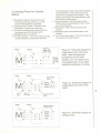
Figure 10: Pictoral diagram for single
phase motor, 115 volts w/plug.
Switch
'-
'-r -White-
Figure 11: Pictoral diagram for
3-phase motor.
CAUTION: IF THE MOTOR RUNS CLOCKWISE
WHEN CONNECTED TO YOUR SINGLE PHASE
POWER SOURCE, YOU MUST DISCONNECT THE
POWER SOURCE, OPEN THE JUNCTION BOX AND
FIND THE CORRECT WIRING CONNECTIONS FOR
THE MOTOR, OR LOCATE THE WIRING CONNECTIONS REQUIRED ON THE MOTOR PLATE ON THE
OUTSIDE OF THE MOTOR.
Different manufacturers provide different wiring
configurations for correcting the rotation of the motor
armature. Therefore, no wiring diagrams for these
motors are provided in this manual. Always consult
the motor plate and/or the wiring diagram inside the
junction box if rotation direction is not correct.