1
"
H
~---
.-
--
-_. =
(
==--
'--
c=
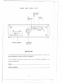
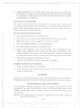
RADIO BACK PANEL VIEW
EXTERNAL
SPEAKER
Jack
PA
SPEAKER
Jack
POWER
Cord Jack
(f)
@
MODEL NO.: MC-4700
DOe 10:
SANTAONIC
AGENCIES
MADE IN TAIWAN
SERIAL NO.
(f)
- POWER +
<t>
PTY,LTD.
SERIAL NUMBER
<t>
AltT
(1)
ANTENNA
Connector
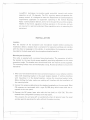
IMPORT ANT!
This above pictorialdisplay shows the location of the various accessory, antenna, and
powerreceptacles,as well asthe SERIAL NUMBER.
<;
You are urged to recordyour model number and your SERIAL NUMBER in the
spaces provided
below:
Model
SERIAL NUM!!ER
-1-
----
]"";;:
-..
..
I
t
-===
--
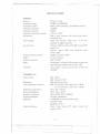
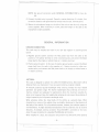
SPECIFICATIONS
f'
GENERAL
Channels
Frequency Range
Frequency Control
Frequency Tolerance
Frequency Stability
Operating Temperature Range
Microphone
10 AM, 10 USB
27.680 to 27.980 MHz
Phase Locked Loop(PLL) synthesized circuitry
:1:0.005%
0.001 %
-20°C to +50°C
Plug-in type, dynamic with push-to-talk switch
and coiled cord
Input Voltage
13.8V DC nominal, 15.9V max., 11.7V min.
(positive or negative ground).
Transmit: AM full mod., 2.2A; SSB 12 watts PEP
output, 2A.
Receiver: AM & SSB with maximum audio
output, 0.6A.
185(W) x 231(D) x 58(H)
3.3 Lbs (1.52 kg)
UHF, SO-239
Illuminated; indicates relative power output and
received signal strength, green receive LED.
LED display; channel, channel 88, TX/RX and
AM/SSB.
Current Drain
Cabinet Dimensions (mm)
Weight
Antenna Connector
Meter
Indicators
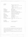
TRANSMITTER
Power output
Modulation
Intermodulation
Distortion
SSB Carrier Suppression
Unwanted Sideband
Frequency Response
Output Impedance
SSB Filter
'I
.
.J
Output Indicators
AM,4 watts
SSB, 12 watts, P.E.P.
AM, high and Iow level
SSB: 3rd and 5th order, better than -25 dB.
7th and 9th order, better than -35 dB.
Better than -55 dB
Better than -50 dB
AM and SSB: 350 to 2500 Hz.
52 ohms, unbalanced
10.695 MHz, 8 pole monolithic type
6 dB @4.2 kHz
60 dB @7.0 kHz
Meter shows relative RF output power; 'red
transmit LED.
-2h -
,
-[
~~j
I
f-
-
RECEIVER
Sensitivity
Selectivity
Cross Modulation
Image Rejection
I.F. Frequency
AM and SSB RF Gain Control
Automatic Gain Control
Squelch
Noise Blanker
Clarifier Range
Audio Output Power
Frequency Response
Distortion
Built-in Speaker
External Speaker (Not Supplied)
- --_.-
SSB: Better than .251J.Vfor 10dB
(S+N)/N at greater than % watt of audio
output
AM: Better than .51J.Vfor 10 dB
(S+N)/N at greater than % watt of audio
output
SSB and AM: 6 dB @ 4.2 kHz, 60 dB @ 7.0 kHz
More than 50 dB
More than 75 dB
AMand SSB: 10.695 MHz
Adjustable for optimum signal reception.
(AGC): Less than 10 dB change in audio output
for inputs from 10 to 500,000 microvolts.
Adjustable; threshold less than .5IJ.V.
RF type, effective on AM and SSB.
:t1.0 kHz Max
3 watts into 8 ohms
350 to 2500 Hz
Less than 10% at 3 watts output.
16 ohms, round
.
8 ohms; disables internal speaker when connected.
PA SYSTEM
Power Output
External Speaker for PA
3 watts into external speaker.
8 ohms (not supplied)
11
I
INTRODUCTION
I
. .1
I
Santronic has combined superb workmanship and modern styling with the very latest
state-of-art circuitry to bring you Barracuda. It has been especially designed to give
you maximum performance and reliability. Your Barracuda is complately factory
aligned and quality assurance tested.
To obtain the maximum benefit and pleasure from your Barracuda please read very
carefully the contents of this manual before attempting to install or operate the
transceiver.
-31:
r
j
-====:
i
<::::::
.
.
.
.
.
.
.
..
.
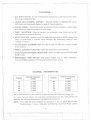
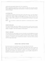
FEATURES
ALL SOLID STATE: IC and Transistorized construction, with Iow current drain,
for a long, trouble-free life.
LARGE LED CHANNEL DISPLAY: Channel number is displayed by use of
LED (light emitting diode) display for ease of channel selection.
CLEAN SIGNAL: Transmitter audio processing circuitry produces a clean signal
with maximum legal modulation, for best range.
QUIET RECEPTION: Effective squelch and automatic noise limiter and an RF
noise blanker for superior quieting.
EFFECTIVE AGE: Receiver amplified automatic gain control (AGC) reduces the
effect of differences in received signal strengths. No distracting "blasting" and
"fading" of signals.
AN EFFICIENT TRANSMITTER: Provides 4 watts on AM and 12 watts on SSB
to the antenna.
PUBLIC ADDRESS FUNCTION: Useful for paging and announcements.
DUAL-COLOR LED MODE INDICATOR: Green for AM mode and Red for SSB
(USB) mode.
EMERGENCY CH88 SWITCH: This switch enables you - to select emergency
channel (CH88) regardless of the channel selector switch setting.
CHANNEL
11
I
,
I
If
I
----
Channel
Channel Frequency
inMHz
68
72
82
86
88
27.680
27.720
27.820
27.860
27.880
INFORMATION
Channel
90
91
94
96
98
Channel Frequency
in MHz
27.900
27.910
27.940
27.960
27.980
The units would have to be returned to Santronic to effect channel changes, etc.
To insure that you obtain the maximum performance from this radio, please read
carefully the following descriptions and operating instructions.
NOTE:
This radio has been designed for operation in the 11 meter Marine Band
Radio Service. It uses a frequency synthesizing circuit with Phase Locked
-4-
--~~t
r
-
Loop(PLL)
techniques
to provide crystal controlled
... - .---
transmit
and receive
operation on all 10 channels. The PLL circuitry assures ultraprecise frequency control. It is designed to meet the Department of Communications
requirements applicable to equipment operating in the Inshore Boating
Radio Communication Service, and is not to be used for any other purpose,
RB244 of the D.O.C. regulations defines operation in this service, and you
are required to read and understand these regulations prior to operating this
equipment.
INSTAllATION
Location
Plan the location of the transceiver and microphone bracket before starting the
installation. Select a location that is convenient for operation and does not interfere
with the driver or passenger in the vehicle. In automobiles, the transceiver is usually
mounted to the dash panel with the microphone bracket beside it.
Mounting and Connection
This radio is supplied with a universal mounting bracket. The transceiver is held in
the bracket by the two thumb screws supplied, permitting adjustment to the most
convenient angle. The bracket must be mounted with the machine screws supplied.
The mounting surface must be mechanically strong. Proceed as follows to mount the
transceiver:
II
I
I
.. d
I
1. After you have determined the most convenient location in your vehicle, hold the
radio with mounting bracket in the exact location desired. If nothing interferes
with mounting it in the desired position, remove the mounting bracket bolts.
Before drilling the holes, make sure nothing will interfere with the installation of
the mounting bolts.
2. Connect the antenna cable plug to the standard receptacle on the rear panel. Most
CB antennas are terminated with a type PL-259 plug which mates with the receptacle on th e rear panel.
3. Connect the DC power input wire
extends from a plug which connects
This prevents the set being left on
and also permits operating the radio
with the fuse (red) to +12V DC. This wire
to the rear panel.
accidentally when all persons leave the vessel
without the engine running.
-5-,-,.",."
-====t
,.--.-.........
"""~,--"""-,--"---"",,-,",-,,,,,,",.,
'
'--'
-
r
1
'
Ii
-.
~._7-
NOTE: See ground connection under GENERAL INFORMATION for more de-
i
tail.
4. Connect the black wire to ground. Consult a marine electrician if in doubt. Any
convenient location with good electrical contact may be used. (remove paint).
5. Mount the microphone hanger on the side of the unit or near the unit, using two
screws supplied. When mounting in a boat, place the hanger on the dash so the
microphone is easily accessible.
GENERAL
INFORMATION
GROUND CONNECTION
This radio may be installed and used in any 12V DC negative or positive ground
system.
1. Negative ground system: Connect the Red power lead from the radio to the
positive or (+) battery terminal or other convenient point, and connect the Black
power lead to the chassis or vehicle frame or (-) battery terminal.
2. Positiveground system: In the case of positive ground system, connect the Black
power lead from the radio to the negative or (-) battery terminal or other convenient point, and connect the Red power lead to the chassisor vehicleframe or
(+) battery terminal.
.
ANTENNA
This radio is designed to operate into a 52 ohm RADIO antenna. Best results will be
obtained from your transceiver if you use a good antenna, properly installed.
A vertically polarized quarter-wavelength whip antenna provides the most reliable
operation and greater range. The shorter loaded-type whip antennas are more attractive, compact and adequate for applications where the maximum possible distance is not required. Also, the loaded whip antennas do not present the problems of
height imposed by- the full quarter-wavelength wh ip.
Whip antennas utilize the metal body of the vehicle as a ground plane. When
mounted on a corner of the vehicle, they are slightly directional, in the direction of
the body of the vehicle. For all practical purposes, however, the radiation pattern is
non-clirectional. A slight directional characteristic will be observed only at extreme
distances. A standard antenna connector (Type SO-239) is provided on the transceiver for easy connection to a standard PL-259cable termination.
When installed in a boat, the transceiver will perform most efficiently when antenna
-6-
r
~~==1
~-_.-
-
r~
- -----
-
,
I
used has been specifically designed for marine applications.
Before installing the transceiver in a boat, consult your dealer for information regarding an adequate grounding system and prevention of electrolysis between fittings in
the hull and water.
i
AC OPERATION
To operate the transceiver from AC current as the power source, you will require a
separate power supply capable of supplying 2.5 amps at a 13.8V DC output with a
nominal input voltage of 240 volts AC, 50/60 Hz. Simply connect the red (+) and
black (-) leads of the transceiver to the corresponding DC terminals of the power
supply.
NOTE:
Do not attempt to operate this transceiver by connecting directly to 240V
AC.
REMOTE SPEAKER
The external speaker jack (EXT. SPKR) on the rear panel is used for remote receiver
monitoring. The external speaker should have 8 ohms impedance. When the external
speaker is plugged in, the internal speaker is disconnected.
PUBLIC ADDRESS
An external 8 ohm 4-watt speaker must be connected to the (PA SPKR) jack located
on the rear panel when the transceiver is used as a public address system. The speaker
should be directed away from the microphone to prevent acoustic feedback. Physical
separation or isolation of the microphone and speaker is important when operating
the PA at high output levels.
OPERATING
INSTRUCTIONS
Barracuda operates on 10 AM channels .and 10 Upper Side Band channels.
When you receive the SSB signal in the proper mode, audio sound may be either too
high pitched or Iow pitched, indicating that your receiver may not be tuned to the
exact same frequency as the transmitter to which it is listening. The Barracuda is
equipped with a Clarifier. By tuning the Clarifier, you can slightly change the frequency of the receiver, so you get a normal tone.
-7mu__'---
.r
-
- --- _00.
-_.
J
-]
"-
-'-.
--~"""','~m
r
II
i
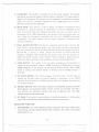
MIC/RF GAIN CONTROL
CLARIFIER
DIGITAL LED
CH88 INDICATOR
CHANNEL INDICATOR
TX/RX
RF POWER/liS" METER
TWO COLOR
I
I
INDICATOR
.
CH'BB
SIGNAL,jPOWER
CHArjNEL
.
TXJRX
uniden
BARRtACUDA
MC14700
MODE SELECTOR
2-MODE INDICATOR
VOLUME/SQUELCH
CONTROL/POWER
-SWITCH
OPERATING
PA-TX/RX
NB/ANL
SWITCH
CHANNEL
1
SWITCH
SELECTOR
SWITCH
CH88 SWITCH
DUAL WATCH SWITCH
CONTROLS
Your Barracuda designed for ease of operation,
ing controls:
is provided with the following
operat-
1. OFF/ON VOLUME: To turn the transceiver on, rotate the control clockwise
past click. To turn the transceiver off, rotate the control counterclockwise past
click. Rotate the control clockwise for a comfortable audio volume level.
2. CHANNEL SELECTOR: This switch is used to select anyone of the 10 Marine
Band channels. Channel 88 has been reserved by the D.O.C. for emergency
communications involving the immediate safety of life of individuals or immediate protection of property. Channel 88 may also be used to render assistanceto a seafarer.
3. MODE SELECTOR: This switch selects AM or SSB (USB) mode of operation.
This selector changes the mode of operation of both transmitter and receiver
simultaneously.
Set the selector to the mode on which you wish to communicate.
For easier
identification
of the mode, LED mode indicator is provided in two different
colors, green for AM and red for SSB (USB).
4. SQUELCH: The squelch control is normally set to a position which just eliminates undesired background noise with no signal present. With the audio volume
adjusted to a satisfactory level, rotate the Squelch control clockwise to the point
where the sound from the speaker is cut off. In this position, there will be no
sound from the speaker until a signal is received. In order to hear weak signals, it
may be necessary to rotate the Squelch control counterclockwise, allowing some
background noise to be heard.
-8-
- ---=r,
'
._~
-
,,-.........---
r
-.-
----------
-
f
.-----.---.
5. CLARIFIER:
The clarifier is normally set to the center position. This
has several uses and can greatly enhance receiver operation. If a receive
slightly off frequency, th is control can be operated to optimize the
signal. This control is primarily intended to tune in SSB signals, but, it
also used to optimize the AM signal.
6. MIKE GAIN: This control is used to adjust,
sensitivity for optimum amount of modulation
feature
signal is
receive
may be
as required, microphone input
in transmit. UNIDEN's marine
band transceivers have been designed to permit the user to attain levels of
modulation up to 100% depending on the setting of the microphone gain control, using the microphone
provided with the unit. UNIDEN's automatic
compression and peak
minimum distortion.
limiting
circuits
assure maximum
modulation
with
7. DUAL WATCH BUTTON: Provides for
Push "DUAL"
button
automatic monitoring of channel 88.
and the watch is set. Now select any other legal channel
and every second the receiver will leave the main channel and sample activity on
Channel 88. If activity is found, receiver will remain on Channel 88 until
message is complete. Channel 88 thus has priority over the main channel. To
disable the watch function, push "DUAL" Button. Whilst in DUAL position.
please note that transmitter is not available to transmit, push CH88 switch.
8. CH88 SWITCH: This switch is for use
when
emerg~ncy
communication
is
needed on the emergency channel, CH88, Pressing the CH88 switch activates
CH88 regardless of the position of the channel selector switch. When CH88
switch is pressed, the channel display is blanked and the CH88 indicator is
activated.
9. PA-TX/RX SWITCH: This control engages the PA function. The PA function
should not be used unless an external speaker is connected. In the TX/RX
position, the PA function is disabled and the radio will transmit and receive on
the selected channel.
10. NB/ANL SWITCH: When the switch is placed in the NB/ANL position, both RF
Noise Blanker and Automatic Noise Limiter circuits are activated. The NB is
very effective for repetitive impulse noise such as ignition noise. The ANL
reduces
annoying hash-type noises.
11. RF GAIN: This control is used primarily to optimize reception in strong signal
areas.Gain is reduced by counterclockwise rotation of the control.
INDICATOR FUNCTION
1. S/RF METER: This meter displays relative transmitter RF output power when
transmitting, and input signal strength when receiving. The meter is illuminated
when power is on.
-9-
-~.,
-"""-"-"-"""-"---'
-----_._-
I
t
r
I
I
2.
I
\
TX/RX INDICATOR: The TX/RX light in the upper right corner of the front
panel lights in red color when the microphone button is pressed and transmitter
is in operation. It lights in green color when the microphone button is released
and the receiver is in operation.
PUSH-TO-TALK MICROPHONE
I
\
The receiver and transmitter are controlled by the push-to-talk switch on the
microphone. Press the switch and the transmitter is activated. Release the switch to
receive. When transmitting, hold the microphone about three inches from your
mouth and speak at a normal voice level.
RECEIVE OPERATING PROCEDURE
1.
Place the PA-TX/RX switch in TX/RX position.
2.
Turn the set on by turning the VOLUME CONTROL clockwise, past click.
NOTE: Microphone must be plugged in for receiver to operate.
3.
Set the VOLUME CONTROL to a comfortable level.
4.
Set the Mode Selector Switch to the desired mode.
5.
Listen to the background noise from the speaker. Turn the SQUELCH CONTROL slowly clockwise, until the noise just disappears. The Squelch is now
properly adjusted. The receiver will remain quiet until a signal is received. Do
not advance the control too far, or some of the weaker signals will not be heard.
6.
Set the Channel Selector to the desired channel.
7.
Adjust the CLARIFIER to clearly receive SSB or AM signals.
TRANSMITOPERATINGPROCEDURE
1. Select the desired channel of transmission.
2.
If the channel is clear, depress the push-to-talk switch on the microphone and
speak in a normal voice.
WARNING
Operation of this equipm~nt requires a valid station license issued by the Department
of Communications. Do not transmit with your equipment until you have a license.
MAINTENANCE
AND ADJUSTMENT
This transceiver is especially designed for the environment encountered in mobile
installations. The use of all solid state circuitry and its light weight result in high
reliability. Should failure occur, however, replace parts only with identical parts. Do
not substitute.
(NOTE: When ordering parts, it is essential to specify the correct model number and
serial number of the unit.)
-10 -
--::r
""""
"""'"
,f
-~-_.
~
,~
~.
~
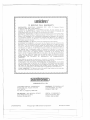
uniden@
12 MONTHS FULL WARRANTY
WARRANTOR. SANTRONIC AGENCIES PTY. LTD. 13 Garema Circuit,
KingsgroveNSW2208 ("SANTRONIC").
ELEMENTS OF WARRANTY. SANTRONIC warrants, for the duration of this
warranty, its UNIDEN Marine Product to be free from defects in materials and
craftsmanship with only the limitation or exclusions set out below.
WARRANTY DURATION. This Warranty shall terminate and be of no further effect
One (1) year after the date of original purchase of the Product or at the time the
Product is (a) damaged or not maintained as reasonable and necessary, (b) modified,
(c) improperly installed, (d) is repaired by someone other Warrantor for a defect or
malfunction covered by this Warranty, or (e) used in a manner or purpose for which
the Product was not intended.
PARTS COVERED. This Warranty covers all components of the Products.
STATEMENT OF REMEDY. In the event that the Product does not conform to this
Warranty at any time while this Warranty is effective, Warrantor will repair the defect
and return it to you prepaid, without charge for parts, service, or any other costs
incurred by Warrantor or its representatives in connection with the performance of
this Warranty. In addition, if the Product contains a defect or malfunction which is
not repaired after a reasonable number of attempts by Warrantor to repair the
Product, the Product or defective component will at our discretion, will be replace
without charge, when the defective product is delivered to the warrantor at 13
Garema Circuit Kingsgrove NSW 2208 free and clear of all liens and encumbrances.
Please note that while the Product will be remedied under this Warranty without
charge. THIS WARRANTYDOES NOT COVER OR PROVIDE FOR THE REIMBURSEMENT OR. PAYMENT OF INCIDENTAL OR CONSEQUENTIAL
DAMAGES.
.
Some states do not allow this exclusion or limitation of incidental or consequential
damages,so the abovelimitationor exclusionmay not apply to you.
PROCEDURE FOR OBTAINING PERFORMANCE OF WARRANTY. In the event
that the Product does not conform to this Warranty, the Product should be shipped
prepaid to Warrantorat 13 GaremaCircuitsKingsgroveNSW2208. THE ORIGINAL
OR COpy OF THE SALES RECEIPT OR OTHER VALID EVIDENCE OF THE
DATE OF THE ORIGINAL PURCHASEMUST ACCOMPANY THIS PRODUCT.
LEGAL REMEDIES. This Warrantygivesyou specificlegalrights, and you may also
have other rights which vary from state to state.
~,
~
'I
I
I
AGENCIES PTY. LTD.
, 11
!
13 GAREMA CIRCUIT, KINGSGROVE
PHONE 7581522, TELEX AA73170
FAX 7502722
P.O. Box 12, Kingsgrove, NSW 2208
BRISBANE: 3/12 BANDALL ST
SLACKS CREEK, OLD 4127
PHONE 07290 1188
MELBOURNE: 446-448 BELL STREET
EAST PRESTON VIC 3072
PHONE: (03) 484 0373
PERTH: 23 GEDDES ST.,
BALACATTA W.A.6021
PHONE: (09) 3443937
\1
.
UTSNO1524XZ
l
@Copyright
1986 Uniden Corporation
.....-.---.......-...
Printed
in Taiwan
j
f~
I