1
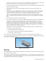
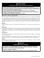
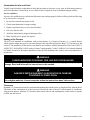
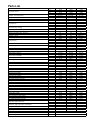
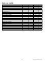
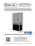
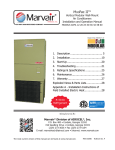
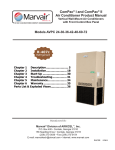
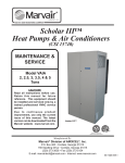
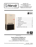
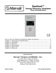
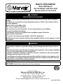
User's Information
GPac Wall Mount
Air Conditioner with Gas Heat
Models AVG24-30-36-42-48-60
WARNING
FIRE OR EXPLOSION HAZARD
Failure to follow safety warnings exactly could result in serious injury, death or property
damage.
Do not store or use gasoline or other flammable vapors or liquids in the vicinity of this or
any other appliance.
WHAT TO DO IF YOU SMELL GAS
• Do not try to light any appliance.
• Do not touch any electrical switch; do not use any phone in your building.
• Leave the building immediately.
• Immediately call your gas supplier from a neighbor’s phone. Follow the
gas supplier’s instructions.
• If you can not reach your gas supplier, call the fire department.
Installation and service must be performed by a qualified installer, service agency or by the
gas supplier.
WARNING
• If the information in these instructions are not followed exactly, a fire, carbon monoxide
poisoning or explosion may result causing property damage, personal injury or loss of
life.
• Read all instructions carefully prior to beginning the installation. Do not begin installation
if you do not understand any of the instructions.
• Improper installation, adjustment, alteration, service or maintenance can cause property
damage, personal injury or loss of life.
• Installation and service must be performed by a qualified installer, service agency or the
gas supplier in accordance with these instructions and in compliance with all codes and
requirements of authorities having jurisdiction.
INSTALLER: Affix the instructions on the inside of the building adjacent to the thermostat.
END USER: Retain these instructions for future reference.
Manufactured By:
Marvair Division of AIRXCEL®, Inc.
®
P.O. Box 400 • Cordele, Georgia 31010
156 Seedling Drive • Cordele, Georgia 31015
(229) 273-3636 • Fax (229) 273-5154
E-mail: [email protected] • Internet: www.marvair.com
Part # 015177/07-2
AVERTISSEMENT
DANGER D'INCENDIE OU D'EXPLOSION
Ne pas respecter strictement les mises en garde de sécurité peut entraîner blessures
graves, mort ou dégâts matériels.
N'entreposez pas et n'utilisez pas d'essence ou autres vapeurs ou liquides inflammables à
proximité de cet appareil ou de n'importe quel autre.
CONDUITE À TENIR SI VOUS SENTEZ LE GAZ
• N'essayez pas de mettre en marche un quelconque appareil.
• Ne touchez à aucun interrupteur électrique, n'utilisez pas de téléphone dans votre
domicile.
• Quittez immédiatement les lieux.
• Appelez immédiatement votre fournisseur de gaz à partir d'un téléphone du voisinage.
Suivez les instructions qu'il vous donnera.
• Si vous ne pouvez pas le joindre, appelez les pompiers.
Installation et interventions doivent être effectuées par un installateur ou une agence de
dépannage qualifiés, ou par le fournisseur de gaz.
AVERTISSEMENT
Si les informations de ces instructions ne sont pas suivies exactement, il peut en résulter
incendie, empoisonnement au monoxyde de carbone ou explosion, causant dégâts
matériels et dommages corporels ou même mort.
• Lisez soigneusement toutes les instructions avant de commencer l'installation. Ne la
commencez pas si vous n'avez pas assimilé toutes ces instructions.
• Une mauvaise exécution d'installation, réglage, altération, intervention ou entretien peut
causer dégâts matériels et dommages corporels ou même mort.
• Installation et interventions doivent être effectuées par un installateur ou une agence de
dépannage qualifiés, ou par le fournisseur de gaz en conformité avec toutes les normes
et exigences des autorités ayant juridiction en la matière.
How To Use This Manual
This manual is intended to be a guide to the use and maintenance of the Marvair® GPac line of wall mounted
air conditioners with gas heat. It contains installation, troubleshooting, maintenance, warranty, and application
information. The information contained in this manual is to be used by the user as a guide only. This manual
does not supersede or circumvent any applicable national or local codes. For information on the efficiency,
cooling and heating performance, please refer to the GPac Product Data Sheets. The most current version of
all Marvair literature can be found on our website at www.marvair.com.
First read Chapter 1 and scan the entire manual before starting the unit as described in the chapter. Chapter 1
contains general, descriptive information.
If a malfunction occurs, follow this troubleshooting sequence:
1. Make sure you understand how the GPac works.
2. Identify and correct installation errors.
3. Refer to the troubleshooting information.
4. Identify defective part(s).
If you are still unable to correct the problem, contact the Factory at 1-800-841-7854 for additional assistance.
GPac Users Information 7/07-2
Table of Contents
Safety Rules..........................................................................................................................4
Start-Up.................................................................................................................................5
Cooling Mode...................................................................................................................6
Heating Mode...................................................................................................................6
Maintenance..........................................................................................................................7
Parts List............................................................................................................................. 11
Warranty..............................................................................................................................13
This is the safety alert symbol . When you see this symbol on the GPac unit and in the instruction manuals be
alert to the potential for personal injury. Understand the signal word DANGER, WARNING and CAUTION.
These words are used to identify levels of the seriousness of the hazard.
! DANGER
Failure to comply will result in death or severe personal injury and/or property
damage.
! WARNING
Failure to comply could result in death or severe personal injury and/or property
damage.
! CAUTION
Failure to comply could result in minor personal injury and/or property
damage.
IMPORTANT is used to point out helpful suggestions that will result in improved installation, reliability or
operation.
Voici le symbole d'alerte concernant la sécurité . Quand vous le voyez sur l'unité GPac et dans
les manuels d'instructions, soyez conscient du risque de blessure personnelle. Assimilez la signification des
mots de mise en garde DANGER, AVERTISSEMENT et ATTENTION. Ils sont utilisés pour qualifier les
niveaux de gravité du risque.
! DANGER
La non-observation entraînera des blessures graves voire mortelles et/ou
des dégâts matériels.
! AVERTISSEMENT
La non-observation pourrait entraîner des blessures graves voire
mortelles et/ou des dégâts matériels.
! ATTENTION
La non-observation pourrait entraîner des blessures et/ou des dégâts
matériels mineurs.
IMPORTANT est utilisé pour mettre en évidence des suggestions utiles qui peuvent améliorer installation,
fiabilité ou fonctionnement.
The manual will be divided into four parts as follows:
• Safety Rules
• Start-Up
• Maintenance
• Warranty
GPac Users Information 7/07-2
WARNING
Failure to observe and follow Warnings and Cautions and these Instructions could result in
death, bodily injury or property damage. Read this manual and follow its instructions and
adhere to all Cautions and Warnings in the manual and on the GPac unit.
AVERTISSEMENT
La non observation et l'ignorance des ces AVERTISSEMENT et ATTENTION et de ces
instructions peut entraîner mort, dommages corporels ou dégâts matériels. Lisez
ce manuel et suivez ses instructions, et tenez compte de tous les ATTENTION et
AVERTISSEMENT dans ce manuel et sur l'unité GPac.
Safety Rules
1. The GPac wall mounted air conditioner with a gas furnace and the area around the unit must be kept clear
and free of any combustible materials, including gasoline and other flammable liquids. See Chapter 4, Safe
Installation Requirements and Chapter 5, Installation in the Installation Instructions.
2. The GPac wall mounted unit must be kept free and clear of insulating material. Insulating materials may
be combustible. Ductwork must be of the correct material and must be properly insulated. Do not use duct
liner or any combustible material on the inside of the supply duct within four feet of the unit. See Porting
and Ductwork section in the Installation Instructions.
3. The proper and safe operation of the unit requires combustion air for operation of the gas heater and
ventilation air for proper operation of the cooling cycle. Do not block the combustion or ventilation air
intake or exhaust. Refer to the Installation Instructions for the required clearances around the unit. The
required clearances are also shown on the Data plate on the unit.
4. Be familiar with signals of a possible lack of or reduction of combustion air. See Air Inlet and Outlet
section of the User's Information.
5. Refer to Start-up section of the User's Information for starting and shutting down the GPac air conditioner
with gas heat.
6. Should the gas supply fail to shut off or if overheating occurs, shut off the gas valve to the unit before
shutting off the electrical supply.
7. Become familiar with all controls and shut-off valves. Make sure you know how to shut off gas and
electrical power to the unit. Do not wait for an emergency before locating the gas valve and the electrical
disconnect switch. If the furnace is to be shut down for an extended period of time, turn off both gas and
electrical power.
8. Do not use this unit if any part has been under water. A flood damaged furnace is extremely dangerous.
Attempts to use the furnace can result in fire or explosion. Immediately call a qualified service technician
to inspect the unit and replace all gas controls, control system parts, electrical parts that have been wet or
to replace the unit if deemed necessary.
9. Each month check:
a. To make certain that the flue vent is not obstructed. (See the Venting of the Furnace section in the
User's Information.)
b. To make sure the vent connector is in place, and is physically sound and without holes or excessive
corrosion. (See Venting section of the Installation Instructions.)
GPac Users Information 7/07-2
c. The supply air and return air duct connections to verify that they are physically sound, are sealed to the
furnace casing. (See Porting and Ductwork section of the Installation Instructions.)
d. To make certain that there are no signs of deterioration of the unit and that the unit is physically sound
without cracks, gaps or sagging.
e. The condensate line to make sure that condensate can flow free from the unit and the line is not
obstructed.
f. The air filters to make certain that they are not dirty. Clean and/or replace as required. The fiberglass
disposable type should be REPLACED before they become clogged. Dirty filters are can severely
restrict air flow and are a common cause of complaints of inadequate heating and cooling.
Filters are located behind the front panel. To change the filter, remove the front panel and slide the
filters out. Replacement filters should be ONLY of the type and size as the original Marvair supplied
filters.
g. To verify that the burner flame is in good adjustment.
Allow the unit to operate for a few minutes to establish normal burning conditions. Look at the flames
on the burners. They should be predominately blue in color and robust in appearance. The flame
should be in the middle of the heat exchanger tubes. Check to see that all the burners are lit and that
the flame does not impinge on the sides of the heat exchanger. Observe the flame. There should be
little or no change to in the shape or size of the flame. Changes in the shape and size of the flame may
indicate a leak in the heat exchanger. See figure 1.
Distorted flame or yellow tips of the natural gas flame or long yellow tips on LP gas flames may be
caused by one or more of the following:
1. lint or dirt inside the burner or burner ports,
2. lint or dirt at the air inlet between the burner and the manifold pipe, or
3. an obstruction over the burner plate.
If any of these are visible, turn the unit off and use a vacuum or a soft brush to clean the affected areas.
It is recommended that the unit be inspected by a qualified service technician to thoroughly check and inspect
the unit prior to each heating season.
Figure 1. Burner Flame
Start-up
Before lighting the unit, smell around the unit for gas. Be sure to smell next to the floor because LP gas is heavier
than air and will settle on the floor.
The gas valve on your unit is equipped with an ON/OFF knob. Use only your hand to turn the knob Never use
tools. If the knob will not push in or turn by hand, do not try to repair it. Call a qualified service technician. Force
or attempted repair may result in a fire or explosion.
GPac Users Information 7/07-2
The GPac air conditioner with gas heat is equipped with an automatic spark ignition system. There is no pilot.
In case of a safety shutdown on units with electronic temperature control, shut main disconnect OFF and then
back ON to reset ignition control. On units with an electro-mechanical thermostat, move the thermostat switch
to OFF and return the thermostat switch to HEAT. On initial start-up of the unit in the heating mode, a burn-off
of excess paint and oils remaining from the manufacturing process may cause some smoking and smell for 5-10
minutes.
Cooling Cycle
1. Set the fan switch to "Auto" and the system switch to "Off".
2. Move the cooling temperature on the wall thermostat to a point higher than the room temperature. Move
the heating temperature to a temperature that is lower than the room temperature.
3. Set the thermostats system switch to "Cool" or "Auto" position. Nothing should operate at this time.
4. Set the time delay in the control box to three minutes. Note that time delay is an option on some GPac
units and may not be on your air conditioner.
5. Remove the cover plate from the thermostat. Slowly lower the thermostat cooling temperature. Once the
indoor fan turns on, allow approximately three minutes for the compressor and outdoor fan to start.
For units equipped with the low ambient control, note that the outdoor fan may not come on immediately, because
it is cycled by refrigerant pressures. Some units have a time delay module which prevents the compressor from
restarting immediately after interruption of power. See Cooling Mode section of the Installation Instructions for
details on the operation of the low ambient control and the time delay.
Heating Cycle
1. Turn off electrical power to the unit.
2. Set thermostat to its lowest setting.
3. Remove heat section access panel.
4. Turn knob on the gas control valve to ON. Do not force. Never light the burner with a match or torch.
ON SWITCH
Figure 2. Gas Control Valve
5. Replace heat section access panel.
6. Turn on electrical power to the unit.
7. Set room thermostat to desired temperature.
8. On a call for heating, the air switch closes, initiating a 30 second pre-purge.
9. At end of pre-purge period, the Spark and Gas valve is energized for up to a 5 second ignition trial. Gas
valve will open.
10.Burners ignite and carryover.
GPac Users Information 7/07-2
11.Flame is detected by the flame sensor and control operates in a steady state condition.
12.Unit continues to heat until the room temperature set point is met.
If ignition is not achieved within 5 seconds, the gas valve is shut off, the inducer keeps running for an
interpurge period of 60 seconds and additional ignition trials follow the specified sequence. If after three trials
for ignition have occurred without proper ignition and flame detection, the control is locked out.
Control may be brought out of lockout by cycling the thermostat or turning the main power off for at least 5
seconds. Control will also attempt another ignition sequence after a one hour after a lock out occurrence.
1. If flame is lost once it has been established, the control will shut off the gas supply within 0.8 seconds and
enter the interpurge period. Control will initiate up to 3 additional trials per normal operation sequence.
2. If flame sensor indicates presence of flame during purge period, when no flame should be present, the
inducer will remain energized but the gas valve will not be energized until the cause of the “false flame” is
removed.
3. If the air pressure switch is closed when the inducer is energized or does not close after the inducer is
energized, the control will wait one minute for the air switch to open or close and then lock out.
4. If the control detects power to the gas valve when it should be off, or if no power when it should be on, the
control will go into lock out with all outputs off.
LED Flash Code
On- Steady
Control operation normal
1 Flash
Open pressure switch, limit switch or flame rollout switch
2 Flashes
Pressure switch stuck closed
3 Flashes
Ignition/flame sensor failure
4 flashes
Repeated flame losses
5 flashes
Internal control fault
6 flashes
Repeated pressure switch losses
Maintenance
WARNING
ELECTRICAL SHOCK, FIRE OR EXPLOSION HAZARD
Failure to follow safety warnings exactly could result in dangerous operation, serious
injury, death or property damage.
Improper servicing could result in dangerous operation, serious injury, death or property
damage.
• Before servicing, disconnect all electrical power to the AVG unit.
• When servicing controls, label all wires prior to disconnecting. Reconnect all wires
correctly.
• Verify proper operation after servicing.
GPac Users Information 7/07-2
AVERTISSEMENT
ELECTRICAL SHOCK, FIRE OR EXPLOSION HAZARD
Ne pas suivre les AVERTISSEMENTS de sécurité à la lettre peut entraîner un
fonctionnement dangereux, des blessures graves ou mortelles ou des dégâts matériels.
Une intervention inappropriée peut entraîner un fonctionnement dangereux, des blessures
graves ou mortelles ou des dégâts matériels.
• Avant d'intervenir, débranchez toute alimentation électrique vers l'unité AVG.
• Quand vous intervenez sur des commandes, étiquetez les fils avant de les débrancher,
afin de les rebrancher tous correctement.
• Vérifiez le bon fonctionnement après une intervention.
Maintenance – Burner and Vent Outlet.
Marvair® strongly recommends that the unit be serviced a minimum of twice a year – once prior to the heating
season and once prior to the cooling season. At this time the filters, evaporator coil, condenser coil, the cabinet,
and condensate drains, the burner flame, the burner and the combustion air inlet and outlet should be serviced
and inspected as described below. Also at this time, the unit should be operated in the cooling and heating cycles
as described in Chapter 2, Start-Up. In addition to this seasonal check-out, the unit should be maintained as
follows:
Air Filter
Replace the air filter whenever it is visibly dirty. Note: Filters must be U.L.C approved or equivalent for use in
Canada.
Indoor Coil
If the coil becomes clogged or dirty, it may be cleaned by careful vacuuming or with a commercial evaporator
cleaning spray. DO NOT use a solvent containing bleach, acetone, or flammable substances. Turn power OFF
before cleaning. Be careful not to wet any of the electrical components. Be sure the unit has dried before
restarting.
Outdoor Coil
Periodically inspect the outdoor coil and the cabinet air reliefs for dirt or obstructions. Remove foreign objects
such as leaves, paper, etc.
If the coil is dirty, it may be washed off with a commercial solvent intended for this purpose. TURN OFF POWER
BEFORE CLEANING! Be sure that all electrical components are thoroughly dry before restoring power.
Cabinet
The cabinet may be cleaned with a sponge and warm, soapy water or a mild detergent. Do not use bleach,
abrasive chemicals or harmful solvents.
WARNING
CARBON MONOXIDE POISONING
A crack or hole in the heat exchanger could result in carbon monoxide gas which can
cause death or serious injury. Carbon monoxide is colorless and odorless. Signs that
there is a hole or crack in the heat exchanger include:
1. Headaches, Nausea or Dizziness.
2. Excessive humidity or heavily frosted windows or a clammy feeling in the structure.
GPac Users Information 7/07-2
AVERTISSEMENT
EMPOISONNEMENT AU MONOXYDE DE CARBONE
Une fissure ou un trou dans l'échangeur thermique peut laisser échapper du gaz avec
monoxyde de carbone qui peut causer des troubles sévères ou mortels. Le monoxyde
de carbone est sans couleur et sans odeur. Les signes pouvant indiquer un problème
d'étanchéité sur l'échangeur thermique sont :
1. Maux de tête, nausées ou vertiges.
2. Humidité excessive ou fenêtres très givrées, ou viscosité sur la structure.
Drains
Regularly check the primary and secondary condensate drains. The secondary drain has a stand pipe. An obstruction
will force water to dump into the middle of the unit and drain out the sides of the GPac air conditioner, causing
discoloration of the side panels. If discoloration is noted, service the drains.
If a commercial drain solvent is used, flush out the drain pan and system with plenty of fresh water to prevent
corrosion.
Lubrication
Oiling of the condenser fan motor or the evaporator blower motor is not recommended.
Burner Flame
Inspect the burner flame periodically during the heating season to ensure proper burner operation.
Light the burners and allow the unit to operate for a few minutes to establish normal burning conditions. Look
at the flames on the burners. They should be predominately blue in color and robust in appearance. The flame
should be in the middle of the heat exchanger tubes. Check to see that all the burners are lit and that the flame
does not impinge on the sides of the heat exchanger. Observe the flame. There should be little or no change
to in the shape or size of the flame. Changes in the shape and size of the flame may indicate a leak in the heat
exchanger. See Figure 3.
Figure 3. Burner Flame
Distorted flame or yellow tips of the natural gas flame or long yellow tips on LP gas flames may be caused by
one or more of the following:
1. Lint or dirt inside the burner or burner ports,
2. lint or dirt at the air inlet between the burner and the manifold pipe, or any obstruction over the burner
plate.
If any of these are visible, turn the unit off and use a vacuum or a soft brush to clean the affected areas.
Burner
Inspect the burners at least once a year, prior to each heating season, for rust, water damage or dust accumulation.
The burner should be replaced if rust or water damage is present. Dust should be removed if present.
GPac Users Information 7/07-2
Combustion Air Inlet and Outlet
Visually inspect both the combustion air inlet and gas outlet at least once a year, prior to the heating season, to
make sure that there is no build up of soot, debris or dirt. If required, clean to maintain adequate air flow.
Service reminder!
Always call a qualified service technician if the unit is not working properly. Before calling, check the following
to be sure service is required:
1. Be sure the electrical disconnect is ON.
2. Check room thermostat for proper setting.
3. Replace any blown fuses or reset circuit breakers.
4. Gas valve must be ON.
5. Air filters should not be plugged, limiting air flow.
6. Make sure all service panels are in place.
Venting of the Furnace
The AVG wall mounted air conditioner with gas heat furnace is a Category I furnace, i.e., a central furnace
which operates with a non-positive vent static pressure and with a flue loss not less than 17%. The furnace is fan
assisted. The installation of the furnace vent must be in accordance with the National Fuel Gas Code (NFGC),
ANSI Z223.1-2000/NFPA 54-2002, and /or Section 7 and Appendix C of the CSA B149.1-00, National Standard
of Canada, Natural Gas & Propane Installation Code; the local building codes; furnace and vent manufacturer’s
instructions.
WARNING
CARBON MONOXIDE POISONING, FIRE, AND EXPLOSION HAZARD
Failure to properly vent this furnace could result in death, personal injury and/or property
damage. Read and follow all the instructions in this section.
WARNING
danger d'empoisonnement au monoxyde de carbone,
d'incendie ou d'explosion
Une mauvaise ventilation de cette chaudière peut entraîner blessures graves ou mortelles
et/ou dégâts matériels. Lisez et respectez toutes les instructions dans cette section.
Clearances
Maintain 18" clearance between the vent hood and anything that would restrict or impede air flow from the hood.
The intake of the combustion air is thru louvers located on the side of the AVG wall mounted air conditioner
with gas heat furnace. Maintain 19" clearance between the louvers and anything that would restrict or impede
air flow into the louvers.
10
GPac Users Information 7/07-2
Parts List
MAJOR PURCHASED PARTS
ACA
ACC
ACD
Compressor, Scroll
Capacitor, Scroll Compressor
Refrigerant R22 (Oz)
Sound Blanket, Compressor
Crankcase Heater, Compressor
60 Hz
Evaporator Coil
Indoor Cap Tube - Cooling
Strainer (.378/.382 by Four .127/.131)
Strainer (.378/.382 by Three .114/.118)
Strainer (.378/.382 by Two .127/.131)
Cap Tube / Strainer Assembly (Alternate)
Distributor - Indoor
Orifice - Cooling
Condenser Coil
Filter Drier
Indoor Motor (HP/RPM)
Capacitor, Indoor
Blower, L.H.
Blower, R.H.
Blower Wheel / Housing
Outdoor Motor (HP/RPM)
Capacitor, Outdoor
Fan Blade (Clockwise Rotation)
High Pressure Control (400 Open, 300 Close)
Low Pressure Control (35 Open, 60 Close)
Filter (2" Thick)
Motor, Economizer (EPA)
Enthalpy Control, H205A (EC)
Mixed Air Relay (MAR)
Mixed Air Sensor (MAS)
GreenWheel Blower, Flanged, 400 CFM
Energy Recovery Wheel
Motor, GreenWheel Drive
Fan Speed Controller (230 Volt)
Belting, 3/16" Round Urethane
Contactor, Compressor, 30 Amp
Contactor, Compressor, 40 Amp
Contactor, Compressor, 30 Amp
Circuit Breaker, 2 Pole, 60 Amp
Circuit Breaker, 3 Pole, 60 Amp
Circuit Breaker, 3 Pole, 40 Amp
Fan Blower Control (BTR)
Lockout Relay (LOR)
Clip for Low Vibration
Relay, Outdoor Fan Motor (OFR)
Relay, B Damper
Low Voltage Transformer (50 VA)
ACA
ACA
ACC/ACD
ACA
ACC
ACD
Transformer (460 to 230 Volts)
Transformer (460 to 230 Volts), GreenWheel
Duct Furnace Heat Module: 45,000 Btu/Hr
Duct Furnace Heat Module: 67,500 Btu/Hr
Duct Furnace Heat Module: 90,000 Btu/Hr
Duct Furnace Heat Module: 75,000 Btu/Hr
Duct Furnace Heat Module: 100,000 Btu/Hr
Duct Furnace Heat Module: 125,000 Btu/Hr
11
AVG42AC
10052
10093
10094
50322
55 / 370
100
20017
n/a
60340
3CZ1404D18 x 36
n/a
n/a
n/a
n/a
n/a
n/a
20116
20093 (.072)
60350
3CZ1402D28 x36
70370
40099
1/2 1075
50360
30090
30092
10-8 DD
40098
1/3 825
50240
30135
T2404-20
70080
70050
81257 (2)
18 x 24
40101
70230
50164
70229
50780
01226
40007
70049
P/80390
50020
n/a
50040
70178
70183
70299
50419
50214
01257
50205
50420
50199
50147
1.5 KVA
P/50007
2.0 KVA
n/a
n/a
n/a
AVG48AC
10202
10203
10204
50294
60 / 440
110
20038
70044
60340
3CZ1404D18 x 36
80660
.070 x 70 (4)
80042
n/a
n/a
20297
n/a
n/a
60345
3CY1303D28 x 36
70370
40099
1/2 1075
50360
30090
30092
10-8 DD
40098
1/3 825
50240
30135
T2404-20
70080
70050
81257 (2)
18 x 24
40101
70230
50164
70229
50780
01226
40007
70049
P/80390
n/a
50030
50040
70178
70183
70299
50419
50214
01257
50205
50420
50199
50147
1.5 KVA
P/50007
2.0 KVA
n/a
n/a
n/a
50413
50414
50415
AVG60AC
10096
10097
10098
50315 (2)
40 / 370
107
20038
70044
60061
3CY1404D18 x 36
n/a
n/a
n/a
n/a
n/a
n/a
20033 (9)
20078 (.088)
60345
3CY1303D28 x 36
70389
40046
3/4 1120
50360
30090
30092
10-8 DD
40098
1/3 825
50240
30135
T2404-20
70080
70050
81257 (2)
18 x 24
40101
70230
50164
70229
50780
01226
40007
70049
P/80390
n/a
50030
50040
70178
70183
70299
50419
50214
01257
50205
50420
50199
50147
1.5 KVA
P/50007
2.0 KVA
n/a
n/a
n/a
GPac Users Information 7/07-2
Parts List (cont'd)
MAJOR PURCHASED PARTS
Direct Spark Ignition Control, 24 VAC, 250 ma
Gas Valve, 2 Stage (3.5/1.2" WC High/Low)
Induced Draft Blower (230 v)
Induced Draft Blower (460 v)
Induced Draft Blower, 3000 RPM, 0.9 A, 230 v
Induced Draft Blower (460 v)
Pressure Switch, Low (0.36" WC PR)
Pressure Switch, High (1.1" WC PF)
Flame Rollout Switch, L270
Spark Igniter
Flame Sensor
In-Shot Burner (2.5 x 4.5)
Limit Control, High (45,000 Btu/Hr)
Limit Control, High (67,500 Btu/Hr)
Limit Control, High (90,000 Btu/Hr)
Limit Control, High (75,000 Btu/Hr)
Limit Control, High (100,000 Btu/Hr)
Limit Control, High (125,000 Btu/Hr)
Limit Switch, High (45,000 Btu/Hr)
Limit Switch, High (67,500 Btu/Hr)
Limit Switch, High (90,000 Btu/Hr)
Limit Switch, High (75,000 Btu/Hr)
Limit Switch, High (100,000 Btu/Hr)
Limit Switch, High (125,000 Btu/Hr)
Suppression Ignition Cable
Nox Screen
Gas Orifice, Natural Gas (Standard)
Gas Orifice, Propane (Standard)
Gas Orifice, Natural Gas (2.30 mm Standard)
Gas Orifice, Propane (1.50 mm Standard)
Relay, Heat/Blower, 460 Volt Only
Relay, Condenser Fan, 460 Volt Only
AVG42AC
50418
20354
n/a
n/a
30064
AVG48AC
AVG60AC
n/a
n/a
n/a
n/a
n/a
n/a
n/a
70372
70372
70372
n/a
n/a
n/a
n/a
n/a
n/a
n/a
n/a
n/a
n/a
n/a
n/a
n/a
n/a
n/a
n/a
n/a
n/a
n/a
20355
20356
50190
50190
n/a
n/a
70377
70373
50190
50190
12
50190
50190
GPac Users Information 7/07-2
Model AVG Air Conditioner with Gas Heat Warranty Policy
If any part of your Marvair® unit fails because of a manufacturing defect within fifteen months from the date
of original shipment from Marvair or within twelve months from the date of original start-up, whichever is the
earlier date, Marvair will furnish without charge, EXW Cordele, Georgia, the required replacement part. Any
transportation, related service labor, diagnosis calls, filter, driers, and refrigerant are not included. The owner
must provide proof of the date of the original start-up. The owner’s registration card filed with Marvair, the
contractor’s invoice, the certificate of occupancy or similar document are examples of proof of the date of the
original start-up.
In addition, if the hermetic compressor fails because of a manufacturing defect within sixty months from the date
of original shipment from Marvair®, Marvair will furnish without charge, EXW Cordele, Georgia, the required
replacement part. Any related service labor, diagnosis calls, filter, driers and refrigerant are not included. Marvair
will pay for non-priority shipping costs of the compressor during the first twelve months of the warranty period.
After the first twelve months of the warranty period, all costs of shipment and risk of loss during the shipment
of the compressor shall be the responsibility of the owner.
In addition, if the heat exchanger in the gas furnace fails because of a manufacturing defect within 120 months
from the date of original shipment from Marvair®, Marvair will furnish without charge, EXW Cordele, Georgia,
the required replacement part. Any related service labor and diagnosis calls are not included.
The owner of the product may ship the allegedly defective or malfunctioning product or part to Marvair®, at
such owner’s expense, and Marvair will diagnose the defect and, if the defect is covered under this warranty,
Marvair will honor its warranty and furnish the required replacement part. All costs for shipment and risk of loss
during shipment of the product to Marvair and back to the owner shall be the responsibility and liability of the
owner. Upon written request by an owner, Marvair may arrange for remote diagnosis of the allegedly defective
or malfunctioning product or part but all costs for transportation, lodging and related expenses with regard to
such diagnostic services shall be the responsibility and liability of the owner.
An owner requesting performance under this Warranty shall provide reasonable access to the allegedly defective
or malfunctioning product or part to Marvair® and its authorized agents and employees.
This warranty applies only to products purchased and retained for use within the U.S.A., Canada, and Mexico. This
warranty does not cover damage caused by improper installation, misuse of equipment or negligent servicing.
THIS WARRANTY CONSTITUTES THE EXCLUSIVE REMEDY OF ANY PURCHASER OF A MARVAIR®
HEAT PUMP OR AIR CONDITIONER AND IS IN LIEU OF ALL OTHER WARRANTIES, EXPRESSED OR
IMPLIED, INCLUDING, WITHOUT LIMITATION, ANY IMPLIED WARRANTY OF MERCHANTABILITY
OR FITNESS FOR USE, TO THE FULLEST EXTENT PERMITTED BY LAW. IN NO EVENT SHALL ANY
IMPLIED WARRANTY OF MERCHANTABILITY OR FITNESS FOR USE EXCEED THE TERMS OF THE
APPLICABLE WARRANTY STATED ABOVE AND MARVAIR SHALL HAVE NO OTHER OBLIGATION
OR LIABILITY. IN NO EVENT SHALL MARVAIR BE LIABLE FOR INCIDENTAL OR CONSEQUENTIAL
DAMAGES OR MONETARY DAMAGES.
THIS WARRANTY GIVES YOU SPECIFIC LEGAL RIGHTS, AND YOU MAY ALSO HAVE OTHER
RIGHTS WHICH VARY FROM STATE-TO-STATE. Some states do not allow limitations or exclusions, so
the above limitations and exclusions may not apply to you.
Rev. 6/06
13
GPac Users Information 7/07-2