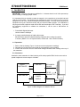
1
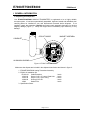
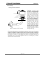
E7000/E7500/E8000
IOM Manual
FLAT GASKET
O-RING
CABLE EXTENSION
SCREWS
HOUSING
Figure 2. E7000/E7500/E8000 Retrofit Parts Kit
B. Precautions
Avoid rough handling of the transmitter. The electronic circuits are of solid state technology but
damage can result from shock in a fall. During unpacking and installation avoid dusty areas as
much as possible. Fine dust or sand can cause erratic operation or failure of the circuitry.
Once installed properly, the transmitter assembly is nearly impervious to environmental effects.
When connecting the cables and connectors, be sure that the screws are securely fastened and
that the connectors are firmly pressed into place. Normally, you will not have to be concerned
with the internal connections unless you are performing maintenance on the assembly.
Double check the installation, wiring, and power supply used to excite the transmitter to ensure
that specifications are adhered to properly and precisely to avoid failure and violation of
warranty.
C. Description
1. General
The transmitter is a single assembly mounted on the flowmeter beneath the register assembly.
It is contained in an aluminum housing 4.25" in diameter and approximately 2" high. It comes
equipped with a standard 1/2" electrical LL19 condulet attached by a brass 1/2" close nipple.
The transmitter uses the mechanical rotation of the flexible drive shaft to turn a magnet
assembly generating an electric pulse. The pulse is generated by a rotating magnet assembly
that has four or eight magnets placed evenly around the assembly.
Page 3 of 14
© 1996-2007 by McCrometer, Inc.
Printed in U.S.A.
Lit# 24512-00 Rev. 1.6/07-07