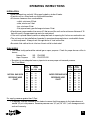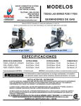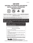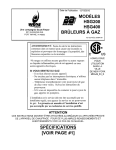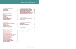
1
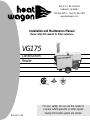
342 N. Co. Rd. 400 East
Valparaiso, IN 46383
219-464-8818 • Fax 219-462-7985
www.heatwagon.com
Installation and Maintenance Manual
Please retain this manual for future reference.
VG175
Construction
Heater
C
Revision 1-06
US
For your safety: Do not use this heater in
a space where gasoline or other liquids
having flammable vapors are stored.
IMPORTANT INFORMATION! READ FIRST
The heater is designed for use as a construction heater under ANSI Z83.7a-2000. The primary
purpose of construction heaters is to provide temporary heating of buildings under construction,
alteration, or repair and to provide emergency heat. Properly used, the heater provides safe, economical heating. Products of combustion are vented outside the area being heated.
The heater IS NOT designed as an Unvented Gas Fired Room Heater under ANSI-Z21.11.2 and
SHOULD NOT be used in the home.
ANSI A119.2(NFPA 501C)-1987 Recreational Vehicle Standard prohibits the installation or storage of LP-gas containers even temporarily inside any recreational vehicle. The standard also prohibits the use of Unvented Heaters in such vehicles.
NFPA-58 1989 STANDARD FOR THE STORAGE AND
HANDLING OF LIQUEFIED PETROLEUM GASES
Use of the heater must be in accordance with this Standard and in compliance with all governing
state and local codes. Storage and handling of propane gas and propane cylinders must be in
accordance with NFPA 58 and all local governing codes.
We cannot anticipate every use which may be made for our heaters. CHECK WITH YOUR
LOCAL FIRE SAFETY AUTHORITY IF YOU HAVE QUESTIONS ABOUT LOCAL REGULATIONS.
Other standards govern the use of fuel gases and heat producing products in specific applications. Your local authority can advise you about these.
FOR YOUR SAFETY
DO NOT USE THIS HEATER IN A SPACE WHERE GASOLINE OR OTHER LIQUIDS HAVING FLAMMABLE VAPORS ARE STORED OR USED.
CONSTRUCTION HEATER GENERAL HAZARD WARNING:
Failure to comply with the precautions and instructions provided with this heater can
result in death, serious bodily injury and property loss or damage from the hazards of
fire, explosion, burn, asphyxiation, carbon monoxide poisoning, and/or electrical
shock.
Only persons who can understand and follow the instructions should use or service
this heater.
If you need assistance or heater information such as an instruction manual, labels,
etc., contact your local Heat Wagon dealer or the manufacturer.
W
A
R
N
I
N
G
Fire, burn, inhalation, and explosion hazard. Keep solid combustibles, such as building materials, paper or cardboard, a safe distance away from the heater as recommended by the instructions. Never use the heater in spaces which do or may contain
volatile or airborne combustibles, or products such as gasoline, solvents, paint thinner, dust particles or unknown chemicals.
Not for home or recreational vehicle use!
If you have read this entire manual and you still have questions, please call us at 219-464-8818
Installation and Maintenance Manual
Model VG175
Construction Heater
Table of Contents:
Page
Safety & Caution . . . . . . . . . . . . . . . . . . . . . . . . . . . . . . . . . . . . . . . . . . . .4
Specifications . . . . . . . . . . . . . . . . . . . . . . . . . . . . . . . . . . . . . . . . . . . . . . .4
Operating Instructions . . . . . . . . . . . . . . . . . . . . . . . . . . . . . . . . . . . . . . . .5
Maintenance . . . . . . . . . . . . . . . . . . . . . . . . . . . . . . . . . . . . . . . . . . . . . . . .8
Troubleshooting . . . . . . . . . . . . . . . . . . . . . . . . . . . . . . . . . . . . . . . . . . . .10
Illustrated Parts Breakdown . . . . . . . . . . . . . . . . . . . . . . . . . . . . . . . . . . .15
Wiring Diagrams . . . . . . . . . . . . . . . . . . . . . . . . . . . . . . . . . . . . . . . . . . .17
Exhaust Flue Pipe Guidelines . . . . . . . . . . . . . . . . . . . . . . . . . . . . . . . . .19
WARRANTY
This heater is guaranteed against defective materials and workmanship for one (1) year from Heat Wagon invoice
date.
Warranty repairs may be made only by an authorized, trained and certified Heat Wagon dealer. Warranty repairs
by other entities will not be considered. Warranty claims must include model number and serial number.
Components are guaranteed to the extent of the component manufacturer’s warranty.
LIMITATIONS
Warranty claims for service parts (wear parts) such as spark plugs, igniters, and flame rods will not be allowed.
Diagnostic parts such as voltage meters and pressure gauges are not warrantable. Evidence of improper fuel usage,
fuel pressures outside of manufacturer’s specification, poor fuel quality, improper electric power, misapplication
and/or evidence of abuse may be cause for rejection of warranty claims.
Labor, travel time, mileage and shipping charges will not be allowed. Minor adjustments to heaters are the responsibility of the dealer. Defective parts must be tagged and held for possible return to the factory for 60 days from
date of repair. The factory will provide a return goods authorization, (RGA) for defective parts to be returned. No
warranty will be allowed for parts not purchased from Heat Wagon.
342 N. Co. Rd. 400 East • Valparaiso, IN 46383
219-464-8818 • 888-432-8924 • Fax 800-255-7985
www.heatwagon.com
SAFETY & CAUTION
• Instructions given in this manual and the applicable regulations of the local authorities
must be followed.
• The unit may be operated only by those persons who have been instructed in its proper use.
• The unit is to be installed and operated in such a way as to ensure the safety of employees and
surroundings.
• Never cover the unit’s air openings.
• Always ensure adequate fresh air supply to the unit.
• Never stand in front of the discharge end of the heater.
• Keep a minimum clearance of 10 feet from the fuel source. Storing and use of liquid fuel must
comply with the regulations and instructions given by the local authorities.
• Unit’s emitted noise level at the range of 3 feet: 74 dBA.
• Do not introduce foreign objects into the unit.
• Do not expose the unit to direct water jets.
• All electric cables outside the unit are to be protected against damage.
• Always disconnect the unit from power supply and turn off the gas supply when maintenance
or service is being performed.
• IF NOT OPERATED WITHIN GUIDELINES OF THESE OPERATING INSTRUCTIONS,
MANUFACTURER WILL NOT BE HELD RESPONSIBLE AND WARRANTY
WILL BECOME VOID.
SPECIFICATIONS
Model No. VG175
Fuels:
Capacity:
Blower:
Electrical Rating:
Fuel Consumption:
Remote Thermostat:
Max. Discharge Temp.:
Duct Size:
Weight (approximate):
Gas Supply:
Vapor Propane or Natural Gas
175,000 BTU/HR*
1,400 CFM
1/2” SP
120 Volts, 10 Amps
NG-175 CFH / Propane-1.9 GPH
On/Off
200ºF @ 0ºF Ambient
8” Dia., 25 ft. max (straight), temp rating 300ºF min.
186 lbs.
Inlet Pressure
Max W.C.
Min W.C.
Vapor Propane 14 W.C.
9” W.C.
Natural Gas
14 W.C.
9” W.C.
Manifold Pressure
W.C.
3”
3.2”
Burner Orifice
.201
.261
*Note: Overfiring this heater above 195,500 BTU(Nat. Gas) or 184,000 BTU(Propane) will result in inefficient combustion. In order to avoid this possibility the factory standard input rates are adjusted 15% below these ratings.
4
OPERATING INSTRUCTIONS
INSTALLATION
• When transporting, use both lifting eyes located on sides of heater.
• Place the unit on a level and non-combustible surface.
• Minimum clearances from combustibles:
- outlet, minimum 10 feet
- sides, minimum 3 feet
- top, minimum 3 feet
- flue pipe exhaust, gas discharge minimum 2 feet
• Manufacturer recommends a free zone of 5 feet around the unit and a minimum distance of 10
feet at the unit’s flue gas openings are to be maintained.
• If the unit is placed indoors, secure an adequate fresh air opening for the burner combustion air.
• The unit may not be installed and operated in premises where explosive or combustible fumes
or dust are present. Always check the regulations of local authorities.
• Be certain that neither the air inlet nor the air outlet is obstructed.
FUEL SUPPLY
• This heater is shipped as either natural gas or vapor propane. Check for proper burner orifice in
burner.
Natural Gas
.261 PN 62182
Vapor Propane
.201 PN 62371-020
• Be certain to use adequate hose or pipe size to ensure proper volume and pressure.
See Chart Below.
NATURAL GAS QUICK
REFERENCE HOSE
CHART
Hose
Length
in Feet
10
25
35
50
75
100
125
150
175
200
225
BTU
175,000
<1PSI 2PSI 5PSI
3/4 3/4
3/4 3/4
3/4 3/4
1-1/4 3/4
1-1/4 3/4
1-1/4 3/4
1-1/4 3/4
1-1/4 3/4
1-1/4 3/4
1-1/4 3/4
1-1/4 3/4
-
VAPOR PROPANE QUICK
REFERENCE HOSE
CHART
Hose
Length
in Feet
10
25
35
50
75
100
125
150
175
200
225
BTU
175,000
1/2PSI 10PSI
3/4 3/4
3/4 3/4
3/4 3/4
3/4 3/4
3/4 3/4
1-1/4 3/4
1-1/4 3/4
1-1/4 3/4
1-1/4 3/4
1-1/4 3/4
1-1/4 3/4
For supply pressures greater than 1/2psi
• A regulator must be installed on the heater to ensure that the pressure to the heater does not
exceed 1/2 psi inlet pressure. Excessive pressures over 1/2 psi (14” W.C.) will damage controls
and void warranty.
5
FUEL SUPPLY (CONTINUED)
• Ensure that for the surrounding temperature, size and capacity of the propane supply cylinder
is adequate to provide the rated Btu/hr input to the heater.
• Visually inspect the hose assembly and ensure that it is protected from traffic, building
materials, and contact with hot surfaces. If it is evident that there is excessive abrasion or wear,
or the hose is cut, replace it immediately.
• Purge air from line and wait 10 minutes for gas to dissipate.
• After installation, check the hose assembly for gas leaks by applying a water and soap solution
to each connection.
• Fuel hose must be UL approved.
• The installation of this heater to a natural gas supply must confirm with all applicable local
codes or, in the absence of local codes, with the National Fuel Gas Code ANSI Z223.1/NFPA 54.
For vapor propane, refer to standard for Storage and Handling of Liquified Petroleum Gases
ANSI/NFPA 58.
ELECTRICAL
• Electric cable extensions must be connected based on the unit capacity and cable length.
• Confirm voltage at heater connection (105V min.) to ensure proper operation.
EXHAUST FLUE PIPE
• The unit is to be connected to a flue pipe with adequate draft, to ensure the proper start and
operation of the unit. Refer to page 19.
• The flue pipe is to be made of non-combustible material and clearances from combustible
materials must be a minimum 8 inches (temperature of flue gases is approximately 410º F).
• The flue pipe and its installation must comply with the regulations and instructions given by
the local authorities.
START UP
• Only people trained in the operation and supervision of this heater should operate
and maintain the unit.
• Check the unit to make sure that there are no visible defects on the control and safety devices
and that the unit has been installed correctly.
1. Check that the control switch on the control box is in position “0” (STOP).
2. Pre-select desired room temperature on the room thermostat. The temperature must be set
higher than the ambient temperature.
3. Open all possible shut-off devices of the fuel supply lines.
6
START UP (CONTINUED)
4. Turn the control switch on the control box to position “1” (HEATING).
5. When the ambient temperature level is low, the burner switches on automatically. The fan
does not switch on until the set temperature (104ºF) of the heat-exchanger has been
reached (will take approximately 1-5 minutes).
• After startup, the heater is operated automatically by the room thermostat and governed by all
control devices, including the safety limit controls.
• The room thermostat (TSTAT) and burner sensor control the running sequences of the
burner and the fan sensor controls the fan function.
• Overheat limit reset (STB) controls and shuts off the heater (burner) in the case of overheating.
• The unit can also be used for ventilation purposes only, if needed.
1. Turn the control switch on the control box to position “2” (VENTILATION).
2. The unit is now in the continuous ventilating mode.
3. Heating is not possible in this mode.
DUCTING (Warm Air)
• Minimum clearance from combustible materials is 4 inches.
• Use steel ducting or fabric ducting capable of withstanding maximum temperature of 300ºF.
• Maximum length of duct: 25’ (straight).
• Duct diameter: 8”.
• Make sure that the duct is safely and properly fastened to the outlet.
• Avoid sharp bends and corners to ensure maximum air flow and avoid back pressure/heat
accumulation in heater.
• FAILURE TO COMPLY WITH THESE RECOMMENDATIONS COULD RESULT IN SHUTDOWN
OF THE HEATER.
SHUT DOWN
• Turn control switch to position “0” (STOP).
• Close fuel supply.
Important!
The air supply fan continues running to cool down the combustion chamber/heat exchanger
and then stops later. The fan can restart for several times before finally switching off!
WARNING!
UNIT MAY BE UNPLUGGED IN EMERGENCY SITUATIONS ONLY. OTHERWISE, DO NOT
STOP THE UNIT BY UNPLUGGING IT. UNIT NEEDS TO COOL DOWN USING ITS OWN
FAN. FAILURE TO COMPLY WITH PROPER SHUT-DOWN PROCEDURES CAN CAUSE
DAMAGE TO THE COMBUSTION CHAMBER, HEAT EXCHANGER, SAFETY FEATURES AND
VOID WARRANTY.
7
MAINTENANCE
Prior to starting any maintenance work be sure to disconnect unit from power supply until
unit cools down fully and fan shuts off! (Shut Down Procedures page 7)
To ensure the proper function of the unit, it must be serviced on regular basis. Maintenance can
be performed, excluding the control devices and safety limit controls, by an authorized trained &
certified Heat Wagon dealer. The control devices and safety limit controls do not need routine
maintenance. If these items fail they must be replaced.
- Do not use any aggressive cleaning agents, which are harmful or environmentally unfriendly,
when cleaning the unit.
- Do not use water jet when cleaning the unit.
- Pressurized air may be used for maintenance. Be careful not to damage the fan blower wheel
with too much pressure.
- Check whether the unit is free from mechanical damage, replace faulty parts as necessary.
- Check fan blower wheel of the fan at regular intervals and clean it when needed.
- Check functionality of control and safety devices regularly.
- Have the flue gas values of the burner checked regularly by authorized agents.
- Be sure to store the unit in a dust free and dry place when it is not used for a long period of
time. Cover the exhaust flue to prevent entry of foreign objects.
8
SERVICE
• The complete unit, including heat exchanger, combustion chamber and burner should be
cleaned from dust and dirt after every heating period, at a minimum of once per year.
-Removal of combustion chamber/heat exchanger:
For proper cleaning of the unit, manufacturer recommends removal of the complete
combustion chamber with heat exchanger. Clean combustion chamber and exchanger tube with
brush. Vacuum all loose ash and soot. Close all cleaning flanges carefully to avoid damage to
gasket material.
-Disassembling of burner:
1. Disassemble four tightening bolts on the combustion chamber flange and remove burner’s
mounting flange. Take care not to damage the flange seal.
2. Pull out the burner. Take care not to damage the burner head and power cable. Clean blower
wheel, ignitor electrode, and flamerod.
Refer to seperate burner manual for adjustment of burner.
9
10
2. The heater
runs for a little
while, but
shuts down. It
won’t come on
again until I
reset the limit
switch.
1. Turn the
heater to
position #1
and nothing
happens.
• Overheat limit switch faulty due to loss of
power
• Restricted airflow
• Incorrect burner manifold pressure
• Burner orifice is improperly sized
• Heater control unit (HCU)
• Burner sensor
• Burner motor relay
• 24 volt transformer
• Power supply cord
• Burner lock out on the burner flame
safeguard control box is engaged
• Overheat limit switch is tripped
VG175 TROUBLESHOOTING
Symptom
Possible Causes
• For propane, use size .201.
For natural gas, use size .261.
• Use a low pressure gauge (0-15 inches of water column) with a 1/8” NPT inlet.
Install gauge in the pressure tap port located on the output side
of the gas valve. Run the heater. Adjust the pressure by turning the pressure
adjusting screw (located on the input side top of the gas valve) counter
clockwise until the gauge reads 3” W.C.(Propane) & 3.2”W.C.(Nat Gas)
• Check for dirt or ice buildup on the air inlet or blower wheel. If using duct on
the air outlet, insure the back pressure does not exceed a static pressure of .25”
W.C. Check with low pressure gauge if necessary (0-15 inches of water column).
• Adhere to the proper shut down procedures.
Power must remain at the unit until it cools down fully. Blower will shut down on
its own when cool. Test overheat limit switch for continuity between the two
male terminals at room temperature. Replace if overheat limit switch
fails test.
• Reset switch, located on the right hand corner (facing the right hand side of the
unit) .
• Using a volt meter, check for 24 volts AC between ground and one of the “T”
terminals on the burner control box. If less than 24 replace transformer.
• Turn on the heater. Check for 120 volts between ground and both black wires
on the relay. Relay is located in the burner control box under the flame
safeguard control. If less than 105 replace relay.
• On the heater control unit (HCU) disconnect the wires from terminals X10 and
X11. Using an ohm meter, check the resistance between the two wires for a
reading of 8K-15K ohms. Replace sensor if out of range.
• On the main terminal block, check for 120 volts between terminals 8 and N
when the 3-position switch is in the HEAT position. If less than 105 replace HCU.
• Test for 120 volts between L1 and N on the main terminal block.
• Turn thermostat off and on.
Possible Solutions
11
4. Burner motor
comes on,
but the heater
won’t ignite.
3. The heater
has a loud
rumbling
sound.
• Rough setting at 4.5. Minor adjustments from the rough settings can be made
to achieve a smooth sounding burner with no soot from the flue pipe.
• Clean with fine sandpaper. Make sure it is free from buildup or cracks.
• Turn off the gas valve, turn on the burner. Use insulated pliers to hold the
ignition wire and short it to ground. Pull the wire away from ground slowly. A
rainbow colored arc should travel between the wire and the ground at a
distance of 3/8 of an inch for a duration of 4-5 seconds.
• Air inlet damper adjustment
• Ignition electrode
• Electronic igniter
• Use a low pressure gauge (0-15 inches of water column) with 1/8” NPT inlet.
Install gauge in the pressure tap port located on the output side of the gas
valve. Run the heater. Adjust the pressure by turning the pressure adjusting
screw (located on the input side top of the gas valve) counter clockwise until
the gauge reads 3” W.C.(Propane) & 3.2”W.C.(Nat Gas). Refer to pipe sizing
charts in the Heat Wagon Engineering Guide. Heater requires 9-14” W.C. inlet
pressure.
• For propane, use size .201.
For natural gas, use size .261.
• Remove flue pipe and use a flashlight to inspect the inside of the heat
exchanger. The access panel is located in the front panel which is welded to
the flue pipe. Clean the inside of the heat exchanger.
• Use a low pressure gauge (0-15 inches of water column) with 1/8” NPT inlet.
Install gauge in the pressure tap port located on the output side of the gas
valve. Run the heater. Adjust the pressure by turning the pressure adjusting
screw (located on the input side top of the gas valve) counter clockwise until
the gauge reads 3” W.C.(Propane) & 3.2”W.C.(Nat Gas). Refer to pipe sizing
charts in the Heat Wagon Engineering guide, Heater requires 9-14” W.C. inlet
pressure. Ensure proper purge procedure (see fuel supply installation).
• Rough setting at 6. Minor adjustments from the rough settings can be made to
achieve a smooth sounding burner with no soot from the flue pipe.
• Clean the burner blower wheel with a small brush.
• Refer to the flue pipe chart in this manual. Check flue for restriction.
Possible Solutions
• Fuel pressure or volume
• Restrict heat exchanger
• Burner orifice size
• Dirt on burner blower wheel
• Flue pipe setup or flue pipe
restrictions
• Gas manifold pressure
• Air damper setting
VG175 TROUBLESHOOTING
Symptom
Possible Causes
12
• Clean the burner blower wheel with a small brush.
• Refer to the flue pipe chart in this manual. Check flue for restriction.
• Dirt on burner blower wheel
• Improper flue pipe setup or flue pipe
restrictions
• Gas manifold pressure
• For propane, use size .201.
For natural gas, use size .261.
• Remove flue pipe and use a flashlight to inspect the inside of the heat
exchanger. The access panel is located in the front panel which is welded to
the flue pipe.
• Incorrect burner orifice size
• Restricted heat exchanger
• Use a low pressure gauge (0-15 inches of water column) with 1/8” NPT inlet.
Install gauge in the pressure tap port located on the output side of the gas
valve. Run the heater. Adjust the pressure by turning the pressure adjusting
screw (located on the input side top of the gas valve) counter clockwise until
the gauge reads 3” W.C.(Propane) & 3.2” W.C.(Nat Gas). Refer to pipe sizing
charts in the Heat Wagon Engineering Guide. Heater requires 9-14” W.C. inlet
pressure.
• Rough setting at 4.5. Minor adjustments from the rough settings can be made
to achieve a smooth sounding burner with no soot from the flue pipe.
• Air damper setting
5. The heater
blows black
smoke out of
the vent stack.
• If there is power at the flame safeguard control and no power out to the
solenoid valve, replace the flame safeguard control. Check for continuity
between the terminals on the solenoid valve coil.
• Gas valve
Possible Solutions
4. Continued
VG175 TROUBLESHOOTING
Symptom
Possible Causes
13
7. The burner
starts, but the
main fan
never comes
on.
6. The burner
seems to
cycle on and
off more than
it should.
• Blower motor
• Current overload on blower motor
• Blower motor relay
• Heater Control Unit (HCU)
• Fan sensor
• Heater Control Unit (HCU)
• On the heater control unit (HCU) disconnect the wires from terminals X12 and
X13. Using an ohm meter, check the resistance between the two wires for a
reading of 8K-15K ohms.
• Turn the 3-position main switch to the fan position. If the blower runs, check the
fan sensor. If it is good, replace the HCU.
• Turn the 3-position main switch to the fan position. If the relay pulls in, check
for voltage between the L1 and L2 terminals. Then check the voltage between
terminals T1 and T2. The voltage should be the same. If it is much lower,
replace the relay.
• Turn the 3-position main switch to the fan position. Check for voltage between
the 2 solenoid coil terminals on the relay. If there is no voltage, the overload is
bad. Replace the motor and blower assembly.
• Turn the 3-position main switch to the fan position. Check for voltage between
terminals T1 and T2 on the motor relay. If the voltage is good, replace the
motor and blower assembly.
• Check for dirt or ice buildup on the air inlet or blower wheel. If using duct on
the air outlet, insure the back pressure does not exceed a static pressure of
.25” W.C. Check with low pressure gauge (0-15 inches of water column).
• On the heater control unit (HCU) disconnect the wires from terminals X10 and
X11. Using an ohm meter, check the resistance between the two wires for a
reading of 8K-15K ohms. Replace sensor if reading is out of range.
• If all of the above check good, replace the HCU.
• Dirt on main air blower or improper setup
of outlet air duct
• Burner sensor
• Use a low pressure gauge (0-15 inches of water column) with 1/8” NPT inlet.
Install gauge in the pressure tap port located on the output side of the gas
valve. Run the heater. Adjust the pressure by turning the pressure adjusting
screw (located on the input side top of the gas valve) until the gauge reads 3”
W.C.(Propane) & 3.2” W.C.(Nat Gas). Refer to pipe sizing charts in the Heat
Wagon Engineering Guide. Heater requires 9-14” W.C. inlet
pressure.
Possible Solutions
• Gas manifold pressure
VG175 TROUBLESHOOTING
Possible Causes
Symptom
14
8. The burner
continues to
run, but the
fan cycles on
and off.
• Use a low pressure gauge (0-15 inches of water column) with 1/8” NPT inlet.
Install gauge in the pressure tap port located on the output side of the gas
valve. Run the heater. Adjust the pressure by turning the pressure adjusting
screw (located on the input side top of the gas valve) until the gauge reads 3”
W.C.(Propane) & 3.2” W.C.(Nat Gas). Refer to pipe sizing charts in the Heat
Wagon Engineering Guide. Heater requires 9-14” W.C. inlet pressure.
• Refer to pipe sizing charts in the Heat Wagon Engineering Guide.
Heater requires 9-14” W.C. inlet pressure.
• On the heater control unit (HCU) disconnect the wires from terminals X12 and
X13. Using an ohm meter, check the resistance between the two wires for a
reading of 8K-15K ohms. If the test falls out of this range, replace fan sensor.
• Turn the 3-position main switch to the fan position. If the blower runs, check the
fan sensor. If it is good, replace the HCU.
• Fuel supply pressure and volume
• Fan sensor
• Heater Control Unit (HCU)
Possible Solutions
• Gas manifold pressure
VG175 TROUBLESHOOTING
Possible Causes
Symptom
Heat Wagon VG175 Parts List
ITEM
1
2
3
4
5
6
7
8
9
11
12
13
15
16
22
23
PART#
HWP 2709001
HWP 2709002
HWP 2709003
HWP 2709004
HWP 2709005
HWP 120001
HWP 2701065
HWP 2709008
HWP 2709009
HWP 2709011
HWP 2701244
HWP 40900
HWP 63956
HWP 2709016
HWP 41000
HWP 1709023
DESCRIPTION
HEATER FRAME
COVER PLATE
SIDE PANELS (2)
REAR HANDLE
BOTTOM PLATE
FLUE COLLAR
WHEEL
WHEEL SHAFT
BURNER CHAMBER ASSEMBLY
FAN GUARD, RIGHT
FAN, COMPLETE
FAN CONNECTION BOX
BURNER VG175
BURNER COVER
MAIN CONTROL BOX
BRACKET, MAIN CONTROL BOX
ITEM
24
25
26
27
28
29
30
PART#
HWP 26400
HWP 21400
HWP 40850
HWP 20579
HWP 20581
HWP 20582
HWP HC1020
DESCRIPTION
MAIN SWITCH
OVERHEAT LIMIT SWITCH (Capillary)
THERMOSTAT BOX
HEATER CONTROL UNIT
FAN SENSOR (FOR POS. #27)
BURNER SENSOR (POS. #27)
POWER CORD & PLUG
NOT SHOWN IN DIAGRAM
HWP 2709031
RADIATION SHIELD (UPPER)
HWP 12000
SMOKE FLUE W/RAIN CAP
HWP 2453
REMOTE THERMOSTAT
HWP 2700428
GASKET FOR BURNER MOUNT
HWP 2704085
SILICONE SEAL - 40850 THERM. BOX
HWP 40SV06
OPTIONAL REGULATOR FOR MORE
THAN 14” W.C.
HWP 210047
RUBBER EDGE SEAL (SOLD PER FOOT)
(30 FEET PER HEATER)
Also see Control Box Parts page 17.
15
WAYNE BURNER
PARTS BREAKDOWN
ITEM
1
2
3
4
5
6
7
8
9
10
11
12
13
14
15
16
17
18
19
20
21
22
23
24
16
PART#
62700-002
16635-002
63244-002
60226
12697-002
100603-008
61624-002
101243-001
63674-001
60177
61755
62899
44
62960-001
62360
15731
63256-001
61843
62374-004
61759
100603-001
62658-001
61684
61830
DESCRIPTION
Bracket, Control Mounting
Washer, Flat #8
Screw, Fillester 10-24 x .250
Bushing, Metal
Screw, HXSL 23 10-24 x .375
Screw, HXSL 8 18 x 1.25
Nipple - 3/4” x 4” TBE Blk
Control, Ignition
Elbow, 3/4” NPT 90º
Bushing, Snap Insulating
Screw, RDPLMC 10-32 x 1.25”
Lid, Control Box
Shutter, Air-Pie
Decal, Carbon Dioxide Warning
Plug, Hole .39” Dia.
Screw, 6-32 x .312 HEXSLT
Plate, Back Housing
Plate, Instruction-Lighting
Valve, Gas VR8305M 4801 H-(HSG)
Chain, Bead-Type
Screw, 6-20 x .375
Cover, Terminal Strip Hole
Pop Rivet .12 x .28
Plug, Hole .453
ITEM
25
26
27
28
29
30
31
32
33
34
35
36
37
38
39
40
41
42
43
44
45
46
47
PART#
62659-004
16201
63103-001
15872
62898-001
60186-004
60016
63957-001
62261-002
62047
62903-001
13026
63402-001
62048
18007
61638-001
60054
62406-002
61651-004
62182
62371-020
63959-001
63375-001
62947-003
DESCRIPTION
Decal, Wiring-Schem S87K
Decal, Date Code
Plug, Window .84” OD
Nut, 5/16 - 18 x .577
Connector, Orifice Holder
Transformer, 120V/24V 50/60 Hz
Elbow, 1/2NPT x 3/4NPT-Reducing
Tube/Housing - (22035-001)
Electrode ASM
Clamp, Cable .44”ID
Control Box, w/strap
Bushing Strain Relief .562 Hole
Bracket, Electrode Mount
Bushing, Universal
Screw, HEXSLT #8 x 1/2” Self Drill
Venturi Asm.
Nut, Hex 10-32
Relay, 24V 50/60 Hz
Motor/Blower, 115V/60Hz 3200 RPM
Orifice, #G(.261”)/6.63MM (nat. gas)
Orifice, #G(.201”)/6.63MM (propane)
Decal, Rating P265F DIN
Wire, Harness - 3 wire (not shown)
Wire, Ignitor Lead - 18” (not shown)
120 Volt 1 PH
ITEM
E1
PART#
HWP 41000
E2
HWP 40850
E3
HWP 40900
S1
S2
B1
B2
S3
X1
X2
HWP 120021
HWP 20579
HWP 20581
HWP 20582
HWP 21400
HWP 36701
HWP 36100
HWP 30330
HWP 36701
HWP 36701
X4
X5
DESCRIPTION
MAIN CONTROL BOX
(Fibox 175x125x100 MM)
THERMOSTAT BOX
(Fibox 125x125x75 MM)
FAN CONNECTION BOX
(Fibox 175x125x75 MM)
MAIN SWITCH
HEATER CONTROL UNIT,
FAN SENSOR (for S4)
BURNER SENSOR (for S5)
OVERHEAT LIMIT SWITCH
TERMINAL BLOCK (E1)
GROUNDING BLOCK (E1)
POWER CABLE & PLUG
TERMINAL BLOCK (E2)
TERMINAL BLOCK (E3)
17
120 Volt 1 PH
18
EXHAUST FLUE PIPE GUIDELINES
CAPACITY OF TYPE B DOUBLE-WALL
VENTS SERVING A SINGLE DRAFT
HOOD-HEATER x 1000 BTU'S
FOR INDOOR APPLICATIONS
TOTAL
LATERAL
VENT
LENGTH,
HEIGHT,H
,H,
L, FEET
FEET
6
0
2
6
12
8
0
2
8
16
10
0
2
10
20
15
0
2
15
30
20
0
2
10
20
30
30
0
2
20
40
VENT DIAMETER, D,INCHES
6
7
8
205
157
149
137
235
180
165
148
255
195
175
154
285
225
198
169
307
249
228
206
186
336
280
237
200
285
217
205
190
320
247
227
206
345
273
245
217
390
316
275
243
430
346
321
295
273
475
394
343
298
370
285
273
255
415
322
303
281
450
355
330
300
525
414
373
328
575
470
443
410
380
650
535
473
415
10
570
455
435
406
660
515
490
458
720
560
525
486
840
675
610
553
930
755
710
665
626
1060
865
784
705
19
We Stock A Complete Line Of Parts & Accessories
DUCTING
THERMOSTAT
LOCK BOXES
HOSES
REGULATORS
342 N. Co. Rd. 400 East
Valparaiso, IN 46383
219-464-8818 • Fax 219-462-7985
www.heatwagon.com