1
Procon
Instructions for Installing, Servicing and
Using Procon 15, 25, 45 and 75 Boilers
RVR.ie
Ireland’s Online Heating Suppliers
Procon
Table of Contents
1.0
2.0
2.0
3.0
4.0
5.0
6.0
7.0
8.0
9.0
10.0
11.0
11.1
11.2
11.3
11.4
11.7
12.0
13.0
14.0
15.0
15.1
15.2
15.3
15.4
15.5
15.5
15.6
16.0
16.1
16.2
16.3
17.0
17.1
17.2
17.3
17.4
17.5
17.6
17.7
18.0
18.1
18.2
18.3
18.4
18.5
18.6
18.7
18.8
18.9
18.10
19.0
19.1
19.2
20.0
20.1
20.3
20.4
20.5
20.6
20.7
20.8
21.0
21.1
22.0
22.2
23.0
24.0
24.1
24.2
General Notes . . . . . . . . . . . . . . . . . . . . . . . .
Product Description . . . . . . . . . . . . . . . . . . . .
Product Description (cont’d) . . . . . . . . . . . . . .
Technical Data & Dimensions . . . . . . . . . . . . . .
Delivery Consignment / Unpacking The Boiler . . .
Boiler Location . . . . . . . . . . . . . . . . . . . . . . .
Installation Clearances . . . . . . . . . . . . . . . . . .
Wall Mounting . . . . . . . . . . . . . . . . . . . . . . .
Gas Connection . . . . . . . . . . . . . . . . . . . . . . .
Water Connection . . . . . . . . . . . . . . . . . . . . . .
Condensate Waste Connection . . . . . . . . . . . . .
Flue . . . . . . . . . . . . . . . . . . . . . . . . . . . . . .
Conventional Flue . . . . . . . . . . . . . . . . . . . . .
Modular Conventional Flue . . . . . . . . . . . . . . .
Room Sealed Flue . . . . . . . . . . . . . . . . . . . . .
Installation of a Horizontal Wall Terminal . . . . . . .
Flue Components . . . . . . . . . . . . . . . . . . . . .
Calculating the Flue Pressure Loss . . . . . . . . . . .
Flue Terminal Positions . . . . . . . . . . . . . . . . . .
Ventilation Requirements . . . . . . . . . . . . . . . .
Hydraulic System Design . . . . . . . . . . . . . . . . .
Low Water Pressure Protection . . . . . . . . . . . . .
Water Treatment, System Cleaning (BS 7592: 1992)
Care With The Use of Solder Flux . . . . . . . . . . . .
Inclusion of Strainers . . . . . . . . . . . . . . . . . . .
Pressure (Safety) Relief Valve . . . . . . . . . . . . . .
Filling the System . . . . . . . . . . . . . . . . . . . . .
Expansion Vessel . . . . . . . . . . . . . . . . . . . . . .
Electrical Connections . . . . . . . . . . . . . . . . . . .
Internal Wiring Diagrams . . . . . . . . . . . . . . . . .
Low Voltage Cables . . . . . . . . . . . . . . . . . . . .
Outside Air Sensor QAC34 . . . . . . . . . . . . . . . .
Optional Extra Control Options . . . . . . . . . . . . .
QAA73 Room Unit Interface . . . . . . . . . . . . . . .
AGU2.500 Clip-In Module Extra Heating Zone . . .
AGU2.511 Clip-In Module BMS Interface . . . . . . .
OCI420 Clip-In Module LPB Communication . . . .
RVA47 Cascade Controller (Grey) & Housing . . . .
RVA46 Zone Controller (Black) . . . . . . . . . . . . .
RVA63 Zone Controller (Grey) & Housing . . . . . . .
System Configurations. . . . . . . . . . . . . . . . . . .
System Type 1 . . . . . . . . . . . . . . . . . . . . . . . .
System Type 2 . . . . . . . . . . . . . . . . . . . . . . . .
System Type 3 . . . . . . . . . . . . . . . . . . . . . . . .
System Type 4 . . . . . . . . . . . . . . . . . . . . . . . .
System Type 5 . . . . . . . . . . . . . . . . . . . . . . . .
System Type 6 . . . . . . . . . . . . . . . . . . . . . . . .
System Type 7 . . . . . . . . . . . . . . . . . . . . . . . .
System Type 8 . . . . . . . . . . . . . . . . . . . . . . . .
System Type 9 . . . . . . . . . . . . . . . . . . . . . . . .
System Type 10 . . . . . . . . . . . . . . . . . . . . . . .
Commissioning . . . . . . . . . . . . . . . . . . . . . . .
Pre-commissioning Checks . . . . . . . . . . . . . . .
LPG Conversion Procedure . . . . . . . . . . . . . . . .
Control Panel . . . . . . . . . . . . . . . . . . . . . . . .
Boiler LMU64 Controller . . . . . . . . . . . . . . . . .
Level One Parameters Review and Alternation . . .
LMU64 Controller, Fault Indication . . . . . . . . . . .
Reviewing LMU64 Operating Information . . . . . .
Reviewing LMU64 Operating Error Codes . . . . . .
LMU64 Operating Error Codes . . . . . . . . . . . . .
Boiler Operating Sequence Numeric Indication . .
First Firing / Burner Commissioning . . . . . . . . . .
Setting the Boiler to Work . . . . . . . . . . . . . . . .
Servicing . . . . . . . . . . . . . . . . . . . . . . . . . . .
Routine Cleaning & Maintenance . . . . . . . . . . .
Full Parameters List . . . . . . . . . . . . . . . . . . . .
Exploded Views & Short Parts List . . . . . . . . . . .
Procon 15, 25 & 45 . . . . . . . . . . . . . . . . . . . . .
Procon 75 . . . . . . . . . . . . . . . . . . . . . . . . . .
.
.
.
.
.
.
.
.
.
.
.
.
.
.
.
.
.
.
.
.
.
.
.
.
.
.
.
.
.
.
.
.
.
.
.
.
.
.
.
.
.
.
.
.
.
.
.
.
.
.
.
.
.
.
.
.
.
.
.
.
.
.
.
.
.
.
.
.
.
.
.
.
.
.
.
.
.
.
.
.
.
.
.
.
.
.
.
.
.
.
.
.
.
.
.
.
.
.
.
.
.
.
.
.
.
.
.
.
.
.
.
.
.
.
.
.
.
.
.
.
.
.
.
.
.
.
.
.
.
.
.
.
.
.
.
.
.
.
.
.
.
.
.
.
.
.
.
.
.
.
.
.
.
.
.
.
.
.
.
.
.
.
.
.
.
.
.
.
.
.
.
.
.
.
.
.
.
.
.
.
.
.
.
.
.
.
.
.
.
.
.
.
.
.
.
.
.
.
.
.
.
.
.
.
.
.
.
.
.
.
.
.
.
.
.
.
.
.
.
.
.
.
.
.
.
.
.
.
.
.
.
.
.
.
.
.
.
.
.
.
.
.
.
.
.
.
.
.
.
.
.
.
.
.
.
.
.
.
.
.
.
.
.
.
.
.
.
.
.
.
.
.
.
.
.
.
.
.
.
.
.
.
.
.
.
.
.
.
.
.
.
.
.
.
.
.
.
.
.
.
.
.
.
.
.
.
.
.
.
.
.
.
.
.
.
.
.
.
.
.
.
.
.
.
.
.
.
.
.
.
.
.
.
.
.
.
.
.
.
.
.
.
.
.
.
.
.
.
.
.
.
.
.
.
.
.
.
.
.
.
.
.
.
.
.
.
.
.
.
.
.
.
.
.
.
.
.
.
.
.
.
.
.
.
.
.
.
.
.
.
.
.
.
.
.
.
.
.
.
.
.
.
.
.
.
.
.
.
.
.
.
.
.
.
.
.
.
.
.
.
.
.
.
.
.
.
.
.
.
.
.
.
.
.
.
.
.
.
.
.
.
.
.
.
.
.
.
.
.
.
.
.
.
.
.
.
.
.
.
.
.
.
.
.
.
.
.
.
.
.
.
.
.
.
.
.
.
.
.
.
.
.
.
.
.
.
.
.
.
.
.
.
.
.
.
.
.
.
.
.
.
.
.
.
.
.
.
.
.
.
.
.
.
.
.
.
.
.
.
.
.
.
.
.
.
.
.
.
.
.
.
.
.
.
.
.
.
.
.
.
.
.
.
.
.
.
.
.
.
.
.
.
.
.
.
.
.
.
.
.
.
.
.
.
.
.
.
.
.
.
.
.
.
.
.
.
.
.
.
.
.
.
.
.
.
.
.
.
.
.
.
.
.
.
.
.
.
.
.
.
.
.
.
.
.
.
.
.
.
.
.
.
.
.
.
.
.
.
.
.
.
.
.
.
.
.
.
.
.
.
.
.
.
.
.
.
.
.
.
.
.
.
.
.
.
.
.
.
.
.
.
.
.
.
.
.
.
.
.
.
.
.
.
.
.
.
.
.
.
.
.
.
.
.
.
.
.
.
.
.
.
.
.
.
.
.
.
.
.
.
.
.
.
.
.
.
.
.
.
.
.
.
.
.
.
.
.
.
.
.
.
.
.
.
.
.
.
.
.
.
.
.
.
.
.
.
.
.
.
.
.
.
.
.
.
.
.
.
.
.
.
.
.
.
.
.
.
.
.
.
.
.
.
.
.
.
.
.
.
.
.
.
.
.
.
.
.
.
.
.
.
.
.
.
.
.
.
.
.
.
.
.
.
.
.
.
.
.
.
.
.
.
.
.
.
.
.
.
.
.
.
.
.
.
.
.
.
.
.
.
.
.
.
.
.
.
.
.
.
.
.
.
.
.
.
.
.
.
.
.
.
.
.
.
.
.
.
.
.
.
.
.
.
.
.
.
.
.
.
.
.
.
.
.
.
.
.
.
.
.
.
.
.
.
.
.
.
.
.
.
.
.
.
.
.
.
.
.
.
.
.
.
.
.
.
.
.
.
.
.
.
.
.
.
.
.
.
.
.
.
.
.
.
.
.
.
.
.
.
.
.
.
.
.
.
.
.
.
.
.
.
.
.
.
.
.
.
.
.
.
.
.
.
.
.
.
.
.
.
.
.
.
.
.
.
.
.
.
.
.
.
.
.
.
.
.
.
.
.
.
.
.
.
.
.
.
.
.
.
.
.
.
.
.
.
.
.
.
.
.
.
.
.
.
.
.
.
.
.
.
.
.
.
.
.
.
.
.
.
.
.
.
.
.
.
.
.
.
.
.
.
.
.
.
.
.
.
.
.
.
.
.
.
.
.
.
.
.
.
.
.
.
.
.
.
.
.
.
.
.
.
.
.
.
.
.
.
.
.
.
.
.
.
.
.
.
.
.
.
.
.
.
.
.
.
.
.
.
.
.
.
.
.
.
.
.
.
.
.
.
.
.
.
.
.
.
.
.
.
.
.
.
.
.
.
.
.
.
.
.
.
.
.
.
.
.
.
.
.
.
.
.
.
.
.
.
.
.
.
.
.
.
.
.
.
.
.
.
.
.
.
.
.
.
.
.
.
.
.
.
.
.
.
.
.
.
.
.
.
.
.
.
.
.
.
.
.
.
.
.
.
.
.
.
.
.
.
.
.
.
.
.
.
.
.
.
.
.
.
.
.
.
.
.
.
.
.
.
.
.
.
.
.
.
.
.
.
.
.
.
.
.
.
.
.
.
.
.
.
.
.
.
.
.
.
.
.
.
.
.
.
.
.
.
.
.
.
.
.
.
.
.
.
.
.
.
.
.
.
.
.
.
.
.
.
.
.
.
.
.
.
.
.
.
.
.
.
.
.
.
.
.
.
.
.
.
.
.
.
.
.
.
.
.
.
.
.
.
.
.
.
.
.
.
.
.
.
.
.
.
.
.
.
.
.
.
.
.
.
.
.
.
.
.
.
.
.
.
.
.
.
.
.
.
.
.
.
.
.
.
.
.
.
.
.
.
.
.
.
.
.
.
.
.
.
.
.
.
.
.
.
.
.
.
.
.
.
.
.
.
.
.
.
.
.
.
.
.
.
.
.
.
.
.
.
.
.
.
.
.
.
.
.
.
.
.
.
.
.
.
.
.
.
.
.
.
.
.
.
.
.
.
.
.
.
.
.
.
.
.
.
.
.
.
.
.
.
.
.
.
.
.
.
.
.
.
.
.
.
.
.
.
.
.
.
.
.
.
.
.
.
.
.
.
.
.
.
.
.
.
.
.
.
.
.
.
.
.
.
.
.
.
.
.
.
.
.
.
.
.
.
.
.
.
.
.
.
.
.
.
.
.
.
.
.
.
.
.
.
.
.
.
.
.
.
.
.
.
.
.
.
.
.
.
.
.
.
.
.
.
.
.
.
.
.
.
.
.
.
.
.
.
.
.
.
.
.
.
.
.
.
.
.
.
.
.
.
.
.
.
.
.
.
.
.
.
.
.
.
.
.
.
.
.
.
.
.
.
.
.
.
.
.
.
.
.
.
.
.
.
.
.
.
.
.
.
.
.
.
.
.
.
.
.
.
.
.
.
.
.
.
.
.
.
.
.
.
.
.
.
.
.
.
.
.
.
.
.
.
.
.
.
.
.
.
.
.
.
.
.
.
.
.
.
.
.
.
.
.
.
.
.
.
.
.
.
.
.
.
.
.
.
.
.
.
.
.
.
.
.
.
.
.
.
.
.
.
.
.
.
.
.
.
.
.
.
.
.
.
.
.
.
.
.
.
.
.
.
.
.
.
.
.
.
.
.
.
.
.
.
.
.
.
.
.
.
.
.
.
.
.
.
.
.
.
.
.
.
.
.
.
.
.
.
.
.
.
.
.
.
.
.
.
.
.
.
.
.
.
.
.
.
.
.
.
.
.
.
.
.
.
.
.
.
.
.
.
.
.
.
.
.
.
.
.
.
.
.
.
.
.
.
.
.
.
.
.
.
.
.
.
.
.
.
.
.
.
.
.
.
.
.
.
.
.
.
.
.
.
.
.
.
.
.
.
.
.
.
.
.
.
.
.
.
.
.
.
.
.
.
.
.
.
.
.
.
.
.
.
.
.
.
.
.
.
.
.
.
.
.
.
.
.
.
.
.
.
.
.
.
.
.
.
.
.
.
.
.
.
.
.
.
.
.
.
.
.
.
.
.
.
.
.
.
.
.
.
.
.
.
.
.
.
.
.
.
.
.
.
.
.
.
.
.
.
.
.
.
.
.
.
.
.
.
.
.
.
.
.
.
.
.
.
.
.
.
.
.
.
.
.
.
.
.
.
.
.
.
.
.
.
.
.
.
.
.
.
.
.
.
.
.
.
.
.
.
.
.
.
.
.
.
.
.
.
.
.
.
.
.
.
.
.
.
.
.
.
.
.
.
.
.
.
.
.
.
.
.
.
.
.
.
.
.
.
.
.
.
.
3
4
5
6
8
8
8
9
9
10
10
11
11
11
12
12
13
14
15
16
16
17
17
17
17
17
18
18
18
20
21
21
21
21
21
22
22
22
23
23
23
24
26
28
30
32
34
34
38
40
42
44
44
44
45
45
47
48
49
49
50
51
51
52
52
53
54
61
61
64
Procon
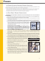
1.0 General Notes
These instructions are intended to assist the installer, commissioning and maintenance technicians and the
user with the application and use of the Procon 15, 25, 45 & 75 gas fired condensing boilers.
Please read this manual fully before commencing the installation of the appliance. The Procon boilers must
be installed by competent persons as defined by local, national and European regulations.
This manual must be handed to the appliance user following completion of the installation. The appliance
must not be left to operate with the outer casing removed.
Conformity Statement
Procon 15, 25, 45 & 75 boilers are manufactured to the highest standards of quality, performance and safety,
in accordance with EC standards and carry the CE mark.
Installation Requirements
All gas appliances must be installed by a competent and qualified person, in accordance with relevant clauses
of applicable standards and recommendations. These include but may not be limited to the following:
• I.S. 813 Domestic Gas Installations
• I.S, 820 Non-Domestic Gas Installations
• All relevant Building Regulations.
• Local Water Bye Laws
• IEE Wiring Regulations
• Health & Safety legislation
Failure to install this appliance correctly could lead to prosecution. It is in your own interest and that of safety
to ensure that the law is complied with.
Manufacturer’s instructions must NOT be taken in anyway as over-riding statutory obligations.
3
Procon
2.0 Product Description
The Procon 15, 25, 45 & 75 wall mounted gas fired condensing boilers are state of the art appliances, which
include a comprehensive range of features.
The appliance must only be used on a sealed and pressurized system. System design must take into account
that the boiler operates on a 20°C Δt.
Wall mounted with compact dimensions
At 750 mm High, 381 mm Deep, and 510 mm Wide for the Procon 15, 25 & 45 boilers, and 750 mm Wide for
the Procon 75 boiler, these provide maximum heat output from minimum dimensions without compromising
serviceability.
Fully modulating heat output
The output of the boiler is fully variable, sliding between (approx.) 24% to 100%, which automatically and
instantly adjusts to match the needs of the system. The percentage of power at any given time can be dictated
by either outside air temperature, flow temperature, return temperature, stored domestic hot water temperature,
room temperature, or a combination of the aforementioned.
Fully condensing stainless steel heat exchanger
The Procon 15, 25, 45 & 75 boilers are designed with extended heat exchanger surface area and is fabricated
from corrosion resistant long-life 316L stainless steel. The unique Spiranox heat exchanger will return operating
efficiencies up to 96.4 % gross (107 % net) at 30°C return temperature.
Extremely low harmful emissions
The Procon 15, 25, 45 & 75 boiler utilizes 100% pre-mix gas/air fed at positive pressure to the metal fibre
sheathed radiant burner. The combustion system incorporates pre-mixed fuel/air control, returning ultra low
emissions to satisfy the most stringent emission regulations in the world currently.
That is: < 31mg/kWh NOx (22 ppm DAF) and < 54mg/kWh CO (50 ppm DAF). The fully modulating nature of
the appliance also reduces emissions by avoiding repeated start/stops and the associated increase in emissions,
which occurs with burner ON/OFF cycling.
Accurate variable burner output control
The pre-mix burner fan has a direct current drive motor with pulse relay counting. This system allows precise
control over fan speed / combustion air volumes. Coupled with a gas valve system set to provide proportionately
measured volumes of fuel to air, this allows extremely accurate and instant variable burner output control to
be achieved.
Natural Gas or LPG
Appliances can be supplied for use with Natural Gas (G20) or Liquefied Petroleum Gas (G31). Conversion Kits
are available from RVR Limited.
4
Procon
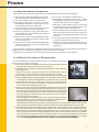
2.0 Product Description (cont’d)
Comprehensive microprocessor control
The Procon 15, 25, 45 & 75 boiler control panel includes a user friendly microprocessor control centre which
manages the entire function of the appliance and encompasses:
1) Management of the essential safety functions of burner ignition and flame monitoring.
2) Water high temperature and flue gas high temperature safety cut out.
3) Modulation of the burner output in conjunction with operating temperature control.
4) Large LCD display screen with clear graphical notations which continuously display operation or fault
status.
5) In built weather compensation to provide direct-on-boiler VT flow temperature (if required).
6) Remote stored hot water temperature control.
7) In built 2 stage boiler frost protection program.
8) In built pump exercise program to avoid standstill seizure.
9) Range rate adjustment which allows the power to be set to accurately match the maximum needs of
the system, with the facility to set different firing rates for heating and hot water generation.
10) Facility to connect optional matched control components which allow the boiler to control;
• A hot water priority system using a 3 port valve or primary charging pump, and hot water sensor attached to a stored hot water cylinder.
• An additional heating circuit pump and 3-port VT valve (if required).
• A multi functional room temperature controller with separate heating and hot water time controls, night
setback, frost protection, and remote interrogation of the boilers’ set-points and function modes.
Room Sealed Option
Utilizing a concentric flue system 125/80 mm ∅ (Air duct / Flue duct), the Procon 15, 25, 45 & 75 can be installed
to take combustion air directly from outside the building. Horizontal and Vertical terminals sets are available.
Inherent safety is achieved by the negative pressure within the boiler case, which in the event of incorrect sealing of the boiler case would result in safe inward air leakage only.
Alternatively the Procon 15, 25, 45 & 75 may be installed as a conventional flue, exhaust only, using an 80 mm
∅ OD Polypropylene flue gas tube and fittings to exhaust the appliance to a suitable flue terminal location,
either vertical or horizontal.
Extended flue pipe lengths
The excess pressure from the combustion system at maximum output is in the order of 400 Pa. This allows
for the Procon 15, 25, 45 & 75 to be flued over considerable distances providing a great deal of flexibility in positioning the boiler.
Designed for ease of maintenance
The Procon 15, 25, 45 & 75 has been engineered for ease of maintenance, even the most major of service
operations being able to be completed easily and quickly without the need for specialist tools.
Guarantee
The warranties available on the Procon 15, 25, 45 & 75 range of boilers is as follows;
Supply Only
Parts Only Warranty, against manufacturing or material defects for a period of 12 months from the
date for delivery.
Supply and Commissioned (By an RVR Engineer)
Parts and Labour Warranty, against manufacturing or material defects for a period of up to 15
months from the date for delivery. In addition to the above warranties, the Primary Heat Exchanger
carriers a five year guarantee against manufacturing or material defect.
5
Procon
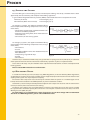
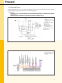
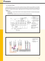
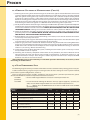
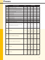
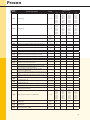
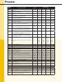
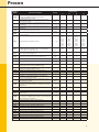
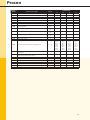
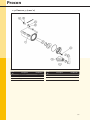
3.0 Technical Data & Dimensions
Nominal Heat Input Net
Nominal Heat Input Gross
Carbon Emissions
100% of Max Output
Carbon Emissions
30% of Max Output
Nominal Heat Output
(50ºC/30ºC)
Design Flow Rate (50ºC/30ºC)
Heat Exchanger Resistance
(50ºC/30ºC)
Nominal Heat Output
(80ºC/60ºC)
Design Flow Rate
(80ºC/60ºC)
Heat Exchanger Resistance
(80°C/60°C)
Residual Head from In-Built
Pump
Maximum Input Gas Rate
Maximum Input Gas Rate
Gas Inlet Pressure
Maximum Flue Gas Volume
Available Fan Pressure
Maximum Water Pressure
Minimum Water Pressure
Maximum Flow Temperature
Power Supply (230V / 50 Hz)
Max Power Consumption
Water Content
Weight (Dry)
Min/Max
Min/Max
G20
G31
G20
G31
kW
kW
kg/kW.h
kg/kW.h
kg/kW.h
kg/kW.h
15H
4.0/15.0
4.4/16.6
0.061
0.078
0.055
0.070
25H
6.5/25.0
7.2/27.7
0.061
0.078
0.055
0.070
45H
12.0/45.0
13.3/49.9
0.061
0.078
0.055
0.070
75H
16.0/70.0
17.7/77.7
0.060
0.077
0.055
0.070
Min/Max
kW
4.3/15.8
7.0/26.0
12.9/47.0
17.0/74.6
l/s
0.188
0.309
0.560
0.888
mH2O
N/A
N/A
N/A
4.7
kW
3.9/14.6
6.3/24.2
11.7/43.5
15.0/67.8
l/s
0.174
0.286
0.519
0.807
mH2O
N/A
N/A
N/A
3.9
mH2O
3.7
1.3
1.00
N/A
m3/h
m3/h
mbar
m3/h
Pa
bar
bar
ºC
A
W
l
kg
1.55
0.57
18.0/50.0
21.36
400
3.00
0.8
90
5
122
5.2
43.0
2.65
1.08
18.0/50.0
40.81
400
3.00
0.8
90
5
129
5.2
43.0
4.65
1.72
18.0/50.0
64.08
400
3.00
0.8
90
5
145
5.2
43.0
6.91
2.60
18.0/50.0
96.84
400
3.00
0.8
90
5
145
8.2
70.0
Min/Max
G20
G31
Min/Max
(Hot)
(Hot)
(Cold)
Connections
HTG Primary Flow
HTG Primary Return
Gas
Condensate Outlet
Condensate Trap Cleaning Point
Electrical Cable Glands
DHW Primary Return (Optional Extra)
DHW Primary Flow (Optional Extra)
(A)
(B)
C)
(D)
(E)
(F)
(G)
(H)
Fig 3.0a – Underside View 15, 25 & 45 Only
Plastic
22 mm
22 mm
22 mm
¾"BSP
¾"BSP
8 × 10 mm
22 mm
22 mm
22 mm
22 mm
22 mm
¾"BSP
¾"BSP
8 × 10 mm
22 mm
22 mm
22 mm
22 mm
22 mm
¾"BSP
¾"BSP
8 × 10 mm
22 mm
22 mm
1 ¼"BSP
1 ¼"BSP
¾"BSP
¾"BSP
¾"BSP
8 × 10 mm
N/A
N/A
Fig 3.0a – Underside View 15, 25 & 45 Only
6
Procon
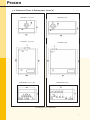
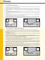
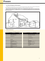
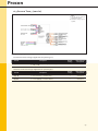
3.0 Technical Data & Dimensions (cont’d)
Plain View 15, 25 & 45 Only
Plain View 75 Only
Front View 15, 25 & 45 Only
Front View 75 Only
Underside View 75 Only
Underside View 15, 25 & 45 Only
All dimensions are in Millimeters
7
Procon
4.0 Delivery Consignment / Unpacking The Boiler
The boiler is delivered as a consignment of a palleted carton containing the boiler and associated fittings,
plus any other optional ancillary flue or control components in separate cartons.
The boiler carton contains:
• Assembled boiler.
• Wall mounting bracket and associated fixings.
• Fittings bag including, condensate waste outlet, outside air sensor (QAC34).
To unpack the boiler, the palleted carton should be laid on the floor. Carefully cut the nylon bands and lift
the fibreboard protective panel. Open the carton top and lift out wall hanging bracket and fittings bag. Remove
packing material and lift away bottomless carton. With 2 people, carefully lift the boiler from palleted carton
by holding the rear chassis only.
To remove the casing from the boiler, turn the two casing screws, on the blue casing strip above the control
panel, through 90°. This will release the casing latches. Pull casing slightly to the front and lift upwards to disengage the casing from the top securing lip. The casing can then be removed.
5.0 Boiler Location
The Procon 15, 25, 45 & 75 boiler is not suitable for installation external to a building. The position chosen for
the boiler must be a structurally sound wall capable of supporting the weight of the boiler and any ancillaries.
The position should allow for access to a nearby foul water drain suitable to accept condensate water, an
alternative is to install a condensate sump receptacle and condense disposal pump which should remove the
condense water to a remote foul water drain suitable to accept condensate water.
The position of the boiler on the wall must be truly plumb vertical to ensure correct operation of the internal
gravity flow condense system. The position for the boiler must satisfy the requirements of BS 6644: 2005 or BS
6798: 1987 as appropriate.
6.0 Installation Clearances
For ease of installation, commissioning, servicing and maintenance the following clearances should be
observed.
NOTE: These distances are MINIMUM and MUST NOT be reduced. Clearance Dimensions relate to ALL models. Dimensions in { } relate to
model 75 only.
8
Procon
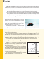
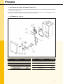
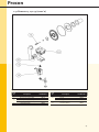
7.0 Wall Mounting
The Procon 15, 25, 45 & 75 boiler is mounted to the wall via a wall-mounting bracket, which interlocks to a rail
mounted on the rear of the boiler.
The wall-mounting bracket should be securely fixed to the wall using suitable fixings for the wall construction and boiler weight. The wall-mounting bracket positioning detail is shown in fig 7.1 for Model 15, 25 & 45;
and fig 7.2 for model 75 only.
The boiler should be carefully lifted by two people and offered up to the wall so that the rail on the rear of
the boiler is just above the mounting bracket. Gently lower the boiler to engage the bracket onto the rail.
Important Notice
When viewed from the side, the North/South axis of the boilers must be vertical. The appliance must not
incline out from the top. If necessary, adjust the position of the boiler at the bottom.
Fig 7.0a – Models 15, 25 & 45 Illustrated
Fig 7.0b – Model 75 Illustrated
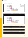
8.0 Gas Connection
The gas connection is located at the base of the appliance in the centre, see fig 8.1 for Models 15, 25 & 45; see
fig 8.2 for model 75.
The pipe size used to supply the appliance must not be smaller than the gas connection size. The connection
to the appliance MUST include an isolation valve and a suitable method of disconnection, installed between
the isolation valve and the appliance.
The gas pipe used to supply the appliance must be installed in accordance with BS 7591: 1988, IGE/UP/2, and
IGE/UP/10 as applicable, and MUST NOT allow a dynamic pressure drop of greater than 1mbar from the meter
to the appliance with all gas appliances operational.
The nominal inlet working pressure measured at the appliance should be 20.0 mbar for Natural Gas (G20),
or 37 mbar for Liquefied Petroleum Gas (G31). The installer should provide a pressure test point adjacent to the
gas inlet connection between the isolation valve and the appliance.
Fig 8.0a – Models 15, 25 & 45 Illustrated
Fig 8.0b
– Models 75 Illustrated
9
Procon
9.0 Water Connection
The Procon 15, 25, 45 & 75 boilers MUST only be installed on a sealed, pressurized heating system. The maximum working pressure of the boiler is 3 bar.
A safety valve set at 3.0 bar MUST be installed into the heating flow pipe adjacent to the appliance and
before any isolation valves. It is recommended that the final working pressure (hot) of the system should not
exceed 2.5 bar.
The system that the boiler is installed onto will require an expansion vessel. The Procon 15 and 25 models
include an integral 10-litre expansion vessel.
Please contact RVR Sales Department for advice on the sizing of an expansion vessel suitable for the systems
requirements.
The flow and return connections should include isolation valves, a drain facility, and a suitable method of
disconnection between the isolation valves and the appliance.
The flow and return connections on the 75 model are 1¼"BSP M (parallel), therefore it is recommended that a fitting
with a tapered thread, such as a Tapered Union or Tapered Socket, be utilized for the connection onto the boiler.
22 mm
Heating
Flow
22 mm
Heating
Return
Fig 9.0a – Models 15, 25 & 45 Illustrated
1 ¼" BSP
Heating
Flow
Fig 9.0b
1 ¼" BSP
Heating
Return
– Models 75 Illustrated
10.0 Condensate Waste Connection
The condensate waste connection is located at the bottom of the appliance, see figs 10.0a & 10.0b.
The condense syphon cleaning point is factory fitted with a heavy black plastic cap which MUST NOT BE
REMOVED apart from during routine maintenance when the syphon is cleaned and must be in place whenever
the appliance is in operation.
WARNING: operating the appliance with the cap removed will result in products of combustion being discharged from the cleaning point.
The condensate waste connection is a ¾"BSP Male threaded stub fabricated from plastic. The installer
must connect to the stub, a condensate waste pipe fabricated from plastic tube & fittings (¾" or 22 mm ∅ overflow pipe is considered suitable). Copper Tube is not acceptable.
The condense waste pipe must fall continuously from the appliance to a nearby foul water drain suitable for
accepting condense waste. If any part of the condensate waste pipe is to be run external to the building or is
at risk of freezing, then the pipe must be suitably insulated to protect against freezing.
If a suitable drain for accepting condense waste is not available nearby and below the boiler, (e.g. boiler
installed in a basement), then a suitable condense sump receptacle with a discharge pump should be installed
below the boiler to remove the condense waste to a suitable remote foul water drain. Available as an optional
extra, Contact RVR Sales Department for more information.
When making the connection to the condense waste pipe, do not use adhesives, it is recommended to
lightly apply a suitable jointing tape (PTFE or similar) and use only light pressure to connect the fittings to the
appliance to avoid damage to the condense waste outlet assembly. It is recommended that a suitable method
of disconnection be fitted, and cleaning points be fitted at regular intervals.
Condense
Cleaning
Point.
22mm ∅
Plastic
Condense
Outlet.
Fig 10.0a – Models 15, 25 & 45 Illustrated
Condense
Cleaning
Point.
22mm ∅
Plastic
Condense
Outlet.
Fig 10.0b – Models 75 Illustrated
10
Procon
11.0 Flue
The flue outlet and combustion air inlet connections to the appliance are located on the top of the appliance;
see fig 11.1. These connections are arranged concentrically with a Female 80 mm ∅ flue gas connection centrally
within a Male 125 mm ∅ air connection.
There are two options for flueing the Procon boiler:
1) Room Sealed, using either concentric 80/125 mm ∅ flue components, or separate 80 mm ∅ flue components; where the air for combustion is taken from outside of the building. When using a room sealed
flue, ventilation to the boiler/s location may not be required, see section 14.0 for further guidance.
2) Conventionally, using 80 mm ∅ flue components for the combustion gases only and air for combustion
being taken from the room or compartment that the appliance is installed. The ventilation to the room
or compartment that the boiler/s are installed MUST be ventilated in accordance with the requirements
of IS 813, IS820, BS5440 or BS6644 as appropriate, see section 14.0 for further guidance.
11.1 Conventional Flue
The Procon 15, 25, 45 & 75 boilers have an excess pressure
combustion system, which coupled with very low flue gas temperatures, allows the appliance to be flued over considerable
distances.
As standard the Procon 15, 25, 45 & 75 boiler is supplied with
a concentric flue outlet on the top of the boiler and utilizes an
80 mm ∅ PPS polypropylene flue gas pipe within a 125 mm ∅
painted metal combustion air pipe, see fig 11.1.
To flue the boiler conventionally, i.e. exhaust only, only the
inner 80mm ∅ PPS socket is used.
The gap between the 80 mm ∅ PPS socket and the 125 mm
∅ painted metal combustion air pipe is left open to allow the Fig 11.1 – Models 15, 25 & 45 Illustrated
air for combustion to enter the boiler from the room in which
the boiler is installed.
Any sections of the flue system that are to be installed horizontally MUST have at least a 3° fall to the boiler
to allow any condensate which may form in the flue system to drain back into the boiler.
The flue system must be gas and water tight, and must be adequately supported over its entire length. Supports at 1 metre intervals are essential.
Care should be taken when selecting a position with a low level discharge, or discharges’ adjacent to windows, doors, etc, as the flue terminal will plume heavily and the white water vapour discharged may cause a
visual nuisance.
The PPS flue components have push together spigot and socket joints, and have soft EPDM O-rings located
in the socket components. To aid assembly and assure that the joints have been fully pushed home, the sealing
EPDM O-rings and male ends of the tubes and fittings should be lightly lubricated with silicone grease.
A range of 80 mm ∅ PPS flue components are available from RVR Boilers Ltd; and is listed on page 15.
11.2 Modular Conventional Flue
The Procon 15, 25, 45 & 75 boilers can be connected onto common
conventional flue, in a modular arrangement; however, due to the
excess pressure combustion system, consideration must be given to
ensure that the excess pressure of a firing appliance/s is not applied to
any non-firing appliance/s.
Therefore, to ensure that the excess pressures are catered for, the
common flue system MUST be designed so that under partial load, the
resistance of the common riser MUST always be of a lesser resistance
than that of any boiler flue branch connecting to the common riser,
furthermore, the use of swept or shoed tee MUST be utilized.
The flue components used shall be pressure tight, and suitable for
a pressure in excess of 400 Pascal’s.
They shall also be of a suitable material for use with condensing
boilers, such as PPS Plastic, or 316L Stainless Steel, etc.
Fig 11.2
11
Procon
11.3 Room Sealed Flue
The Procon 15, 25, 45 & 75 boilers have an excess pressure combustion system, which coupled with very low
flue gas temperatures, allows the appliance to be flued over considerable distances.
The Procon 15, 25, 45 & 75 boilers are fitted with a concentric flue outlet on the top of the boiler and uses a
female 80 mm ∅ PPS polypropylene flue gas pipe within a male 125 mm ∅ painted metal combustion air pipe, see
fig 11.1. To connect to the standard concentric flue components supplied by RVR a flue adaptor is required.
The flue system must be installed to have at least a 3° fall to the boiler to allow any condensate which may
form in the flue system to drain back to the boiler.
The flue system must be gas and water tight, and must be adequately supported over its entire length. Supports at 1-metre intervals are essential.
Care should be taken when selecting a position with a low level
discharge, or discharges’ adjacent to windows, doors, etc, as the flue
terminal will plume heavily and the white water vapour discharged
may cause a visual nuisance.
The concentric flue components have push together spigot and socket joints. Both the inner PPS flue gas tube, and the outer combustion air
tube have soft EPDM O-rings located in the socket components.
To aid assembly and assure that the joints have been fully pushed
home, the sealing EPDM O-rings and male ends of the tubes and fittings
should be lightly lubricated with silicone grease. A range of concentric
flue components are available from RVR Ltd; and is listed on page 15.
Fig 11.3 – Models 15, 25 & 45 Illustrated
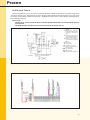
11.4 Installation of a Horizontal Wall
Terminal
Rear Outlet Assembly Method
The following procedure applies to rear flue terminal position.
1) With the boiler mounted in position, see section 7.0, draw a horizontal line on
the wall 210 mm (15, 25 & 45 models) above the top of the boiler. See fig 11.4a.
2) Mark the center of the flue spigot on the wall, remove the boiler from its hanging bracket and carefully position to one side. Draw a vertical line from the
center mark of the flue spigot to intersect the horizontal line. See fig 11.4a.
3) At the intersection of the horizontal and vertical lines, cut a 130 mm ∅ hole
with a core drill. See fig 11.4a.
4) Measure the wall thickness ‘W’ in millimeters, add 155 mm (15, 25 & 45 models), or 200 mm (75 Model) to achieve total length ‘TL’ of flue pipe required.
5) Mark the Horizontal Wall Terminal a distance of ‘TL’ from the outer edge of
the Air Pipe. Both tubes should be cut flush and square with each other,
and any burrs removed. See fig 11.4b.
6) Re-position the boiler onto the hanging bracket, as detailed in section 7.0.
7) Fit the Flue Adaptor to the top of the boiler and lubricate the two seals
with silicone grease.
8) Lubricate the male ends of the concentric bend and the flue adapter with
silicone grease; locate the flue adapter onto the flue outlet connection on
top of the boiler, and gently push home. Locate the bend on top of the
flue adapter, and gently push home.
9) Locate the wall bezel plate onto the wall terminal assembly and position the
terminal through the previously prepared hole from outside the building.
10) Locate the bezel plate onto the wall terminal for the inside face of the wall.
Lubricate the male ends of the concentric bend with silicone grease.
11) Locate concentric tubes into bend and gently push fully home. Ensure
that the plain section of the external part of the air inlet tube is located
uppermost. See fig 11.4c.
12) Fix internal and external wall bezel plates with fixings provided. See fig 11.4c.
Fig 11.4a
Fig 11.4b
Fig 11.4c
12
Procon
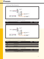
11.4 Installation of a Horizontal Wall Terminal (cont’d)
Side Outlet Assembly Method
The following procedure applies to horizontal, side flue terminal position.
1) With the boiler mounted in position, see section 7.0, draw
a horizontal line along the wall 210 mm above the top of
the boiler. This line should rise at approximately 3° from
the horizontal toward the terminal position to allow any
condensate to drain through the boiler. See fig 11.4d.
2) On the adjacent sidewall, draw a vertical line 130 mm (15,
25 & 45 models), or 176 mm (75 model) from the wall that
the boiler is mounted on. Continue the horizontal line
previously marked on the sidewall, See fig 11.4d
3) At the intersection of the horizontal and vertical lines, cut
a 130 mm ∅ hole with a core drill. See fig 11.4d.
4) Measure the wall thickness ‘W’ in millimeters and the dis- Fig 11.4d
tance between the side of the boiler and the adjacent
sidewall (L1).
For the 15, 25 & 45 models, add 275 mm to the sum of Length
‘L1 + W’, to achieve total length ‘TL’ of flue piperequired.
For the 75 model, if flueing to the LEFT, add 122 mm to
the sum of Length ‘L1 + W’, to achieve total length ‘TL’ of
flue piperequired; If flueing to the RIGHT, add 678 mm
to the sum ofLength ‘L1 + W’, to achieve total length ‘TL’
of flue pipe required.
If ‘TL’ is greater than 845 mm , then additional flueextensions will be required.
5) Mark the Horizontal Wall Terminal, and flue extensions
if required, a distance of ‘TL’ from the outer edge of the
Air Pipe. Both tubes should be cut flush and square with
each other, and any burrs removed. See fig 11.4e.
6) Re-position the boiler onto the hanging bracket, as detailed in section 7.0.
Fig 11.4e
7) Fit the Flue Adaptor to the top of the boiler and lubricate
the two seals with silicone grease.
8) Lubricate the male ends of the concentric bend and the
flue adapter with silicone grease, locate the flue adapter
onto the flue outlet connection on top of the boiler, and
gently push home. Locate the bend on top of the flue
adapter, and gently push home.
9) Locate the wall bezel plate onto the wall terminal assembly and position the terminal through the previously
prepared hole from outside the building.
10) Locate the bezel plate onto the wall terminal for the inside face of the wall.
11) Lubricate the male ends of the concentric bend with
silicone grease. Locate concentric tubes into bend and
gently push fully home. Ensure that the plain section of
the external part of the air inlet tube is located uppermost. See fig 11.4f.
12) Fix external wall bezel plate with fixings provided (fig 11.4f).
Fig 11.4f
13
Procon
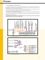
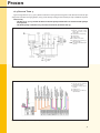
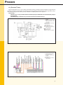
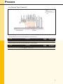
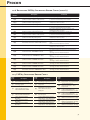
12.0 Calculating the Flue Pressure Loss
The excess pressure available from the boiler fan for overcoming the frictional resistance of the flue system is
400 Pa. The adjacent table lists the resistances of the flue components, which will assist the designer in calculating the resistance of the total flue system.
As with all vertical flue systems, thermal up-draught is generated in the vertical sections of a flue, the graph
below (fig 12.1) shows the Thermal Up-draught generated, in Pa’s, which can then be deducted from the total
flue resistance.
If the resistance of the total flue system exceeds 400 Pa’s, this will result in a reduction of the boiler output.
The graph below (fig 12.2) shows the available maximum boiler output in relation to flue resistance.
Concentric Flue Components
Standard Wall Terminal
Vertical Discharge Wall Terminal
Vertical Terminal
1000 mm Flue Extension
500 mm Flue Extension
93° Bend
45° Bend
80 mm ∅ PPS Flue Components
Concentric to Twin Pipe Adapter
Exhaust Pipe Terminal
Air Pipe Terminal
1000 mm Flue Extension
500 mm Flue Extension
93° Bend
45° Bend
Thermal Up-draught Graph
15H
25H
45H
75H
4.0
4.0
4.0
2.5
1.25
2.5
1.25
5.0
5.0
5.0
4.0
2.0
4.0
2.0
8.0
8.0
8.0
6.0
3.0
6.0
3.0
16.0
16.0
16.0
12.0
6.0
12.0
6.0
1.5
1.0
2.0
1.5
0.75
1.5
0.75
3.0
2.5
4.0
3.0
1.5
3.0
1.5
5.0
4.0
7.0
5.0
2.25
5.0
2.25
10.0
8.0
15.0
9.0
4.5
9.0
4.5
Boiler Output / Flue Resistance Graph
Fig 12.0a – Thermal Up-draught when flue gas
temperature 80ºC and outside temperature -5° C.
A = Flue insulated or within the building.
B = Flue un-insulated and exterior to the
building.
Fig 12.0b – Effect of the flue system
resistance on the boiler output.
14
Procon
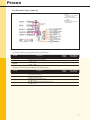
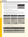
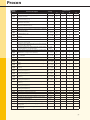
13.0 Flue Terminal Positions
The flue terminal of the Procon 15, 25, 45 & 75 boilers’ will plume water vapour, heavily and care must be taken
when selecting the terminal position to ensure that a “nuisance situation” is not created.
Where the flue terminal discharges within 2 metres of ground or any upper part of the building where
people have general access, i.e. balcony level, etc., a terminal guard MUST be fitted to prevent the terminal
from being touched.
Fig 13.0 – Minimum Clearances
Minimum Distance
All Dimensions are in millimeters, See Fig 13.0
Dimension
A
B
C
D
E
F
G
H
I
Description
Directly below an opening,
air brick, window, etc.
Below gutters, soil pipes,
drain pipes, etc.
Below eaves
Below balconies, car port
roof, etc.
Vertically from soil pipes,
drain pipes, etc.
From internal or external
corners.
Above ground, intersecting
roof, balcony level, etc.
From a surface facing the
terminal.
From a terminal facing the
terminal.
Minimum
Distance
Dimension
300
J
75
K
200
L
200
M
150
N
300
P
300
Q
2000
R
2000
S
Description
From an opening, door,
window, etc., in a car port
Vertically from a terminal on
the same wall.
Horizontally from a terminal
on the same wall.
Above an opening, window,
etc.
Horizontally to an opening,
window, etc.
Above a level roof (base of
terminal).
Q From adjacent wall (edge
of terminal).
From adjacent opening
window.
From any other flue terminal.
Minimum
Distance
1200
1500
300
500
300
500
500
1000
600
Note: Dimensions highlighted in BOLD are not recommended locations.
15
Procon
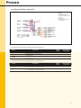
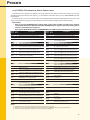
14.0 Ventilation Requirements
The room or space in which the Procon 15, 25, 45 & 75 boiler is installed may need to be ventilated in accordance with BS 5440: Part 2:2000, or BS 6644: 2005, as appropriate.
The table below details the ventilation required for individual Procon 15, 25, 45 & 75 boiler installations
ONLY.
Conventional Flue Installation
Room Installation. Natural Ventilation direct
to outside.
Room Installation. Natural ventilation from
adjacent room, which is directly ventilated to
outside.
Compartment Installation. Natural Ventilation
direct to outside.
Compartment Installation. Natural ventilation
from adjacent room, which is directly
ventilated to outside.
Room
Room Installation. (Consideration shall be
given to provide general ventilation for
cooling purposes).
Compartment Installation, room sealed flue.
Natural ventilation direct to outside.
Compartment Installation. Natural ventilation
from adjacent room. Adjacent room similarly
ventilated direct to outside
15H
25H
45H
40cm2
110cm2
190cm2
40cm2
110cm2
190cm2
N/A
75cm2 High, 150cm2
145cm2 High,
Low Level
290cm2 Low Level
225cm2 High,
450cm2 Low Level
350cm2 High,
700cm2 Low Level
150cm2 High,
300cm2 Low Level
290cm2 High,
580cm2 Low Level
450cm2 High,
900cm2 Low Level
N/A
15H
25H
45H
75H (*1)
NIL
NIL
NIL
140cm2 High & Low
Level
75cm2 High & Low
Level
75H (*1)
140cm2 High,
280cm2 Low Level
145cm2 High & Low 225cm2 High & Low 350cm2 High & Low
Level
Level
Level
150cm2 High & Low 290cm2 High & Low 450cm2 High & Low 700cm2 High & Low
Level
Level
Level
Level
Important Notice
The Ventilation Requirements detailed above are for guidance purposes and are relevant for single appliance installations ONLY.
For further information on different ventilation options/requirements, for single or multiple boiler installations, please refer to BS 5440: Part 2:2000 and BS 6644: 2005, as appropriate.
*1 – Consideration shall be given for the Summer Usage of the boiler, and the appropriate ventilationallowance applied, as detailed in BS 6644: 2005.
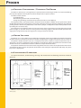
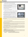
15.0 Hydraulic System Design
The Procon 15, 25, 45 & 75 boiler can be operated to serve a heating load as either;
• Constant Temperature, the option of adjusting the desired set-point temperature between 20 °C and 85 °C.
• Direct-On-Boiler weather compensated flow temperature.
• Hot Water Production, on a priority basis.
The Procon 15, 25, 45 & 75 boilers are designed to operate
with a 20°C ΔT, the heating & hot water loads shall be designed
around a 20°C ΔT, operating the boiler on a reduced ΔT will result
in a reduced boiler output.
Where the system index circuit/s have a greater hydraulic resistance than that of the residual head pressure available from
the internal boiler pump {16, 31, 47}, or chosen boiler pump {75},
then a low loss header must be used, with the boilers pump
delivering the water to the low loss header.
Where multiple boilers are to be installed, a low loss header
must be used, with the boiler primary pumps delivering the water to the low loss header. Non-return valves MUST be fitted to
each boiler to prevent short-circuiting. See 18.8 System Type 8.
Where the system has multiple pumped circuits that are proposed to operating at the same time, then sub headers, both flow
and return, should be used with non-return valve being installed Fig 15.0
directly after each pump to prevent re-circulation. See Fig 15.0
16
Procon
15.1 Low Water Pressure Protection.
A low water pressure switch has been incorporated into the boiler and therefore an external unit is not required. The activation setting of the switch is 0.5 bar, with a 0.3 bar differential; therefore the system pressure
must be in excess of 0.8 bar for the switch to activate and allow the appliance to function.
15.2 Water Treatment and System Cleaning
The entire primary system MUST be thoroughly cleaned and flushed to remove debris, flux residues,
etc. before opening the boiler isolation valves & admitting water to the boiler.
Particular care must be taken where the Procon boiler is being retro-fitted into an old/existing system,
as system silt or magnetite can be very damaging to the new boiler.
Following cleaning and flushing the system MUST be dosed with a good quality water treatment to
prevent corrosion and the formation of scale. A suitable corrosion inhibitor known as INIBAL is available
from RVR Limited.
FAILURE TO OBSERVE THESE REQUIREMENTS WILL RENDER THE WARRANTY ON THE APPLIANCE VOID.
Cleaning, flushing and water treatment must be carried out in accordance with the requirements of
BS 7593:1992, prior to commissioning the boiler.
Repeated draining and refilling of the system, without replenishment of water treatment, must be
avoided, as this is very damaging to the boiler. The boiler must not operate without the system water being correctly and adequately treated, and maintained, with an appropriate level of corrosion inhibitor.
15.3 Care With The Use of Solder Flux
The Procon 15, 25, 45 & 75 boiler has a heat exchanger fabricated from 316L Stainless Steel. It is
most important that the compatibility of any flux is checked with the supplier before use, and that any flux
manufactures recommendations are strictly followed with regards to use in conjunction with Stainless Steel.
15.4 Inclusion of Strainers
The return pipework MUST include some method of filtering or straining. The filter or strainer must be fitted with isolation valves to allow easy cleaning with the minimum amount of water loss and water replenishment.
15.5 Pressure (Safety) Relief Valve
In accordance with BS 5440: 2000 and BS 6644: 2005, as applicable, the installer shall install as suitably sized
Pressure (Safety) Relief Valve.
The location of this valve is important with respect to the applied pressure of the boiler circulation pump, it
is therefore recommended to locate the Pressure (Safety) Relief Valve on the flow pipe i mm ediately adjacent to
the boiler; furthermore, there must not be any means of isolation between the boiler and the Pressure (Safety)
Relief Valve.
17
Procon
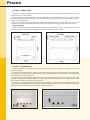
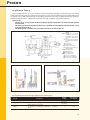
15.5 Filling the System
The Initial filling of a sealed heating system, and subsequent refilling, must be by a method that has been
approved by the local authority and complies with building regulations.
In general Water Regulation Advisory Scheme (WRAS) recommendations will be acceptable in Ireland.
Domestic (In-House)
Fluid Category 3 (C-3)
Non Domestic (Other than In-House)
Fluid Category 4 (C-4)
For Category 3 systems, the approved method of filling
must comprise of the following components in the arrangement shown;
• Control Valve incorporating a Double Check Valve on
the Mains Cold Water pipework.
• Temporary Connecting Hose, which must be disconnected after use.
• Control Valve, on the heating system.
Fig 15.5a
For Category 4 systems, the approved method of filling
must comprise of the following components in the arrangement shown;
• Control Valve.
• Strainer.
• Verifiable Backflow Device with Reduced Pressure
Zone (RPZ Valve)
• Incorporating a ‘Type BA’ Air Gap.
Fig 15.5b
• Tundish.
• Control Valve.
Further more, in accordance with BS 6644: 2005 system with an input greater than 70kW (nett), an automatic
water replenishment unit shall be installed to automatically replenish any lost or evaporated water.
Please refer to BS 6644: 2005 for allowable water replenishment methods for use with sealed/pressurized
heating systems.
Please contact RVR Limited for more information.
15.6 Expansion Vessel
In accordance with BS 5440: 2000, BS 6644: 2005, WRAS Regulations, and Local Authority Water Regulations,
as applicable, the installer shall install a suitably sized, and approved, Expansion Vessel to ensure that the water
capacity of the system has ample expansion capacity.
The location of the expansion vessel shall only be isolatable from the system via a Lockable Type Service
Valved, which shall be locked in the OPEN position, to prevent accidental isolation.
Furthermore, a drain facility should be provided adjacent to the expansion vessel to aide the routine maintenance, overhaul, of the vessels Air Pressure setting.
The Procon 15 & 25 boilers only, are supplied with an internal 10-litre expansion vessel. This vessel is suitable
for a system with a maximum capacity of 100 litres. This is based upon a Cold Fill Pressure of 1.0bar, and a Final
Working Pressure (HOT) of 2.5bar.
For information on a comprehensive range of expansion vessels that comply with current British
Standards and WRAS Regulations, please contact RVR Boiler Sales.
18
Procon
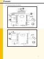
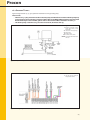
16.0 Electrical Connections.
In accordance with BS 5440: 2000, BS 6644: 2005, WRAS Regulations, and Local Authority Water Regulations,
as applicable, the installer shall install a suitably sized, and approved, Expansion Vessel to ensure that the water
capacity of the system has ample expansion capacity.
The location of the expansion vessel shall only be isolatable from the system via a Lockable Type Service
Valve which shall be locked in the OPEN position, to prevent accidental isolation.
Furthermore, a drain facility should be provided adjacent to the expansion vessel to aid the routine maintenance, overhaul, of the vessel’s Air Pressure setting.
The Procon 15 & 25 boilers ONLY, are supplied with an internal 10-litre expansion vessel. This vessel is suitable
for a system with a maximum capacity of 100 litres. This is based upon a Cold Fill Pressure of 1.0bar, and a Final
Working Pressure (HOT) of 2.5bar.
For information on a comprehensive range of expansion vessels that comply with current Standards
and WRAS Regulations, please contact RVR Limited.
Fig 16.0a – Connection Details for Models 15, 25 & 45
*1 – Parameter Change Required.
Fig 16.0b – Connection Details for Model 75
*1 – Parameter Change Required.
19
Procon
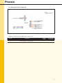
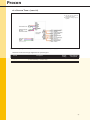
16.1 Internal Wiring Diagrams
Fig 16.1a – Internal Wiring Diagram for Models 15, 25 & 45
Fig 16.1b – Internal Wiring Diagram for Model 75
20
Procon
16.2 Low Voltage Cables
All low voltage cables should be of a suitable screened type for
24-volt data transfer.
The Outside Air Sensor (QAC34), and optional QAA73 unit and Hot
Water Sensor (QAZ36), all require Low Voltage Cables.
The adjacent table gives guidance on the size of cable required
for the length of cable required.
All low voltage cables should be keep away from mains voltage
cables as much as possible as electrical interference from Mains
Voltage cables will adversely affect the operation of the boiler and
its controls. The screening of the cables must be earthed.
Cable Details
Length (mtrs)
Cable (∅ mm 2)
Up to 35
0.25
35 to 70
0.5
70 to 140
1.0
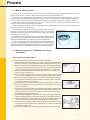
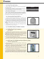
16.3 Outside Air Sensor QAC34
If weather compensated flow temperatures are required (recommended for best seasonal efficiency and comfort), then the Outside
Air Sensor must be installed and electrically connected to the boiler.
The Outside Air Sensor MUST be installed on an exterior wall which
is North facing, away from any artificial heat influences such as ventilation discharges, lights, etc, and MUST not be installed in direct
sunlight.
The Outside Air Sensor complete with 5 mm ∅ wall fixing and screw
is supplied with the boiler. See Fig 16.3.
Fig 16.3
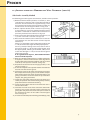
17.0 Optional Extra Control Options
17.1 QAA73 Room Unit Interface
(OpenTherm)
The QAA73 Room Unit Interface (available as an optional extra) not
only provides room temperature control for day set-point, night-time
set-point and frost protection, but also includes individual day programming for heating and hot water control, and also displays the
boiler error message, if set to the OpenTherm Plus mode.
With the use of an AGU2.500 Clip-In Module, and additional Heating
Circuit can also be time controlled, see Item 17.2.
For further information concerning installation and programming,
please refer to the separate QAA73 Installation and Maintenance Manual.
Fig 17.1
17.2 AGU2.500 Clip-In Module Extra Heating Zone
(Part No – 96.38000-7003)
With the use of an AGU2.500A109 Clip-In Module, a second heating
zone can be activated.
When used in conjunction with a QAA73 Room Unit, this second
heating zone can operate under the same temperature dictates as
heating zone 1, or separately under time control only.
When a QAA73 Room Unit is NOT being used, the RU connections
(X10-01) MUST be linked so the time clock for the second heating zone
time clock can be accessible via the boiler fascia.
If a mixing value is required to acco mm odate lower operating temperatures from that of Heating Zone 1, then a QAD36 flow sensor will be required, available as an optional extra. Please refer to instructions supplied
with the Clip-In Module for programming instructions (Ref. – LAGU2).
Fig 17.2
21
Procon
17.3 AGU2.511 Clip-In Module BMS Interface
(Part No – 96.38000-7005)
With the use of an AGU2.511 Clip-In Module, the boiler controller can
communicate with a BMS System.
This Clip-In Module has three 240V (50Hz) progra mm able outputs
that can be configured to respond to the operational status of the
boiler, for remote monitoring, such as, Healthy, Run and Lock-Out.
This Clip-In Module can also accept a 0-10V dc or 020mAmp input
signal for Set-point Temperature, or Percentage Output control.
Please refer to instructions supplied with the Clip-In Module for programming instructions (Ref. - LAGU).
Fig 17.3
17.4 OCI420 Clip-In Module LPB
Communication
(Part No – 96.38000-7004)
With the use of an OCI420 Clip-In Module, the Optional Extra Controls detailed from 17.5 onwards can also be utilized.
One Clip-In Module is required per boiler in a Multiple Boilerarrangement.
Please refer to instructions supplied with the Clip-In Module for programming instructions (Ref. - LOCI).
Fig 17.4
17.5 RVA47 Cascade Controller (Grey) & Housing
The RVA47 Cascade Controller (Grey) is a comprehensiveunit that can
be wall or control panel mounted, and can control upto twelve Procon 15,
25, 45 & 75 boilers. The RVA47is supplied with 2 No QAD21 System Sensors
(flow & return) anda QAC32 outside air sensor. Each Procon boiler MUSTbe
fitted with an OCI420 Communication Clip-In Module, see item 17.4.
In addition to boiler control, the RVA47 can provide the drivesignal
for a heating circuit pump and can provide control for storeddomestic
hot water, with the RVA47 providing the drive signal fora hot water
primary circuit pump.
External control input to the RVA47 can be by either, a VoltFree contact (e.g. time clock), 0-10v analogue input, a QAA70, QAA50 or QAA10 Fig 17.5
Modulating Room Unit.
Heating flow temperatures are weather compensated variable (QAC32 supplied), if constant temperature is
required, a620Ω resistor needs to be installed in place of the outside air sensor.
If more than twelve boilers need to be controlled, then additional RVA47 Cascade Controllers can be connected to the first unit in a ‘Master/Slave’ arrangement. Each subsequent ‘Slave’ RVA47 can control up to twelve
boilers each.
Standard features include Pump Overrun, Boiler Load Rotation, Frost Protection, and Pump Exercise program.
Please refer to instructions supplied with the RVA47 for programming instructions (Ref. - LRVA47QR/LRVA47S).
22
Procon
17.6 RVA46 Zone Controller (Black)
The RVA46 Zone Controller (Black) is a match controller for the RVA47
(Grey), and is located in the Left-Hand position of the RVA47 Housing.
The RVA46 can provide the drive signals for the Zone Circulation
pump and Mixing Valve (Supplied by Others).
If a mixing value is required to acco mm odate lower operating temperatures from that of the other Zones, then a QAD21 flow sensor will
be required, available as an optional extra.
External control input to the RVA46 can be a QAA70, QAA50 or
QAA10 Modulating Room Unit.
Please refer to instructions supplied with the RVA46 for programming instructions (Ref. - LRVA46QG/LRVA46S)..
Fig 17.6
17.7 RVA63 Zone Controller (Grey) & Housing
The RVA63 Controller (Grey) is a comprehensive controller that can
be wall or control panel mounted. The Procon boiler MUST be fitted
with an OCI420 Communication Clip-In Module, see item 17.4.
The RVA63 can provide the drive signals for two heating primary
pumps and mixing valves (if required) and can provide control for
stored domestic hot water, with the RVA63 providing the drive signal
for a hot water primary circuit pump.
If a mixing value/s is required to acco mm odate lower operating
temperatures from that of the other Zones, then a QAD21 or 26 flow
sensor will be required per zone, available as an optional extra.
External control inputs to the RVA63 can be by either, Volt Free EnFig 17.7
able contact (e.g. time clock), or QAA70, QAA50, QAA10 Modulating
Room Units. An external control input is required per zone. The RVA63 can also be linked to an RVA47 for Multiple
boiler installations.
Please refer to instructions supplied with the RVA46 for programming instructions (Ref. - LRVA46QG/LRVA46S).
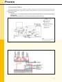
18.0 System Configurations.
The Procon 15, 25, 45 & 75 boilers can be connected to a number of different types of heating and hot water
systems. Depending upon how the boiler is to be utilized will depend upon how the boiler is wired and configured in the boilers parameters.
The following System Types show standard Hydraulic layouts, wiring diagrams, and the necessary parameter
changes. If the system you have installed is not shown in one of these standard layout, we would recommend
that you consult with RVR Boilers Technical Department for further advice.
If the System Type to be installed requires parameters to be changed, these will need to be undertaken during the commissioning of the boiler.
To access the ‘Engineer Level’, press and hold the ▲▼ PROG buttons simultaneously, for approximately 3
second, until H90 appears on the screen. Use the ▲ and ▼ PROG buttons to access the required parameter
number, and use the + and – buttons to alter/adjust the required parameter value. On completion of satisfactory
adjustment/s to a/any parameter, the INFO button must be pressed to store the amendments and to return to
the normal operating display.
A full list of Parameter and Default Values in listed in Section 23.0
Please Note;
When changing Parameter No 552 (System Hydraulics’) the pump connections K1 and K2 for the internal
pump and the external Heating Circuit may vary.
On the Procon 15, 25 & 45 boilers the internal pump wiring may need to be re-located from the factory
position, as detailed on the System Type Wiring Diagrams.
Procon 15 & 25 – K1 (Terminals 16 & 17) to position K2 (Terminals 13 & 14),
Procon 45
– K2 (Terminals 13 & 14) to position K1 (Terminals 16 & 17),
23
Procon
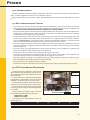
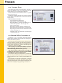
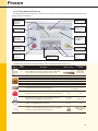
18.1 System Type 1.
Typical single Procon 15, 25, 45 & 75 boiler installation serving heating only.
Please note:
• The Procon15, 25 & 45 models include an internal pump and therefore an external boiler pump may
not be required. The hydraulic resistance of the Index Circuit MUST NOT exceed the amount of the
Residual Head pressure available, please refer to the Technical Data detailed in Section 3.0
• The boiler pump on the Procon 75 must be wired to K2 (Terminals X02-03)
Legend
C External Controller, either
QAA73 Room Unit, or Volt
Free Enable
OS Outside Air Sensor (QAC34)
SV Safety Valve
IV Isolation Valve
LSV Lockable Service Valve
MCWM Cold Water Main DOC Drain
Off Cock
Fig 18.1a – Hydraulic Layout
Notes
*1 Only fit one type of Room
Temperature Control.
Fig 18.1b – Wiring Diagram for Models 15, 25 & 45
24
Procon
18.1 System Type 1 (cont’d)
Notes
*1 Only fit one type of Room
Temperature Control.
Fig 18.1c – Wiring Diagram for Model 75
Potential Parameter Changes Applicable to System Type 1.
Line ID
H554 -b3
Description
Weather Compensation / Constant Temperature
{0 = Constant Temp, 1 = Variable Temp}
Default
Setting
New Setting for
This System
1
As Required
25
Procon
18.2 System Type 2.
Typical single Procon 15, 25 & 45 boiler installation serving heating and domestic hot water (priority) via a 3
Port Valve.
Please note;
• The Procon15, 25 & 45 models include an internal pump and therefore an external systempump
may not be required. The hydraulic resistance of the Index Circuit MUST NOT exceed the amountof
the Residual Head pressure available, please refer to the Technical Data detailed in Section 3.0
• This configuration is not reco mm ended for the Procon 75, please consider System Type 3.
Legend
C External Controller, either
QAA73 Room Unit, or Volt
Free Enable
OS Outside Air Sensor (QAC34)
SV Safety Valve. IV Isolation
Valve
LSV Lockable Service Valve.
S/T Hot Water Sensor (QAZ36), or
Volt Free Enable.
CWM Cold Water Main
DOC Drain Off Cock
Notes
Diverter Valve MUST be installed to
spring return to Heating, NOT Hot
Water.
Fig 18.2a – Hydraulic Layout
Notes
*1 Only fit one type of Room
Temperature Control.
*2 Parameter Change may be
required.
Fig 18.2b – Wiring Diagram for Models 15, 25 & 45
26
Procon
18.2 System Type 2 (cont’d)
Notes
*1 Only fit one type of Room
Temperature Control.
*2 Parameter Change may be
required.
Fig 18.2c – Wiring Diagram for Model 75 (Not Recommended, please consider System Type 3)
Potential Parameter Changes Applicable to System Type 2.
Line ID
H554 -b3
H558-b2
Description
Weather Compensation / Constant Temperature
{0 = Constant Temp, 1 = Variable Temp}
Weather Compensation / Constant Temperature
Default
Setting
New Setting for
This System
1
As Required
0
As Required
27
Procon
18.3 System Type 3
Typical single Procon 15, 25, 45 & 75 boiler installation serving a heating and domestic hot water (priority)
with individual charging pumps, using a low velocity mixing header.
Please note;
• The Procon15, 25 & 45 models include an internal pump and therefore an external boiler pumpis
not required.
• The boiler pump on the Procon 75 must be wired to K2 (Terminals X02-03)
Legend
C External Controller, either
QAA73 Room Unit, or Volt
Free Enable
OS Outside Air Sensor (QAC34)
SV Safety Valve.
IV Isolation Valve
LSV Lockable Service Valve.
S/T Hot Water Sensor (QAZ36), or
Volt Free Enable
CWM Cold Water Main DOC Drain
Off Cock
DOC Drain Off Cock
Fig 18.3a – Hydraulic Layout
Notes
*1 Only fit one type of Room
Temperature Control.
*2 Parameter Change may be
required.
Fig 18.3b – Wiring Diagram for Models 15, 25 & 45
28
Procon
18.3 System Type 3 (cont’d)
Notes
*1 Only fit one type of Room
Temperature Control.
*2 Parameter Change may be
required.
Fig 18.3c – Wiring Diagram for Model 75
Essential Parameter Changes Applicable to System Type 4.
Line ID
H587 -b6
Description
HWS Charging Pump (Standing Operation) {16, 31}
{0 = OFF, 1 = ON}
Default
Setting
New Setting for
This System
0
1
Default
Setting
New Setting for
This System
1
As Required
0
As Required
Potential Parameter Changes Applicable to System Type 3.
Line ID
H554 -b3
H558-b2
Description
Weather Compensation / Constant Temperature
{0 = Constant Temp, 1 = Variable Temp}
HWS Production Control
{0 = Sensor (QAZ36), 1 = Volt Free Enable}
29
Procon
18.4 System Type 4.
Typical single Procon 15, 25, 45 & 75 boiler installation serving two heating zones and domestic hot water (priority) with individual charging pumps, using a low velocity mixing header. AGU2.500 Clip-In Module required.
Please note;
• The Procon15, 25 & 45 models include an internal pump and therefore an external boiler pumpis
not required.
• The boiler pump on the Procon 75 must be wired to K2 (Terminals X02-03)
Legend
C External Controller, either
QAA73 Room Unit, or Volt
Free Enable
OS Outside Air Sensor (QAC34)
SV Safety Valve
IV Isolation Valve
LSV Lockable Service Valve
S/T Hot Water Sensor (QAZ36), or
Volt Free Enable
CWM Cold Water Main DOC Drain
Off Cock
Fig 18.4a – Hydraulic Layout
Notes
*1 Only fit one type of Room
Temperature Control.
*2 Parameter Change may be
required.
*3 Heating Zone 1
*4 Heating Zone 2, via AGU2.500
Clip-In Module.
Fig 18.4b – Wiring Diagram for Models 15, 25 & 45
30
Procon
18.4 System Type 4 (cont’d)
Notes
*1 Only fit one type of Room
Temperature Control.
*2 Parameter Change may be
required.
*3 Heating Zone 1
*4 Heating Zone 2, via AGU2.500
Clip-In Module.
Fig 18.4c – Wiring Diagram for Model 75
Essential Parameter Changes Applicable to System Type 4.
Line ID
H516
H554-b5
H587-b6
Description
Summer/Winter Changer Over
Heating Zone 2 Flow Sensor Present
{0 = NO, 1 = YES}
HWS Charging Pump (Standing Operation) {16, 31}
{0 = NO, 1 = YES}
Default
Setting
18
New Setting for
This System
30
1
0
0
1
Default
Setting
New Setting for
This System
1
As Required
0
As Required
Potential Parameter Changes Applicable to System Type 4.
Line ID
H554 -b3
H558-b2
Description
Weather Compensation / Constant Temperature
{0 = Constant Temp, 1 = Variable Temp}
HWS Production Control
{0 = Sensor (QAZ36), 1 = Volt Free Enable}
31
Procon
18.5 System Type 5
Typical single Procon 15, 25, 45 & 75 boiler installation utilizing an AGU2.500 Clip-In Module serving two heating zones, one with a mixing valve, and domestic hot water (priority) with individual charging pumps, using a
low velocity mixing header. AGU2.500 Clip-In Module and QAD36 flow sensor required.
Please note;
• The Procon15, 25 & 45 models include an internal pump and therefore an external boiler pump is
not required.
• The boiler pump on the Procon 75 must be wired to K2 (Terminals X02-03)
Legend
C External Controller, either
QAA73 Room Unit, or Volt
Free Enable.
OS Outside Air Sensor (QAC34)
SV Safety Valve
IV Isolation Valve
LSV Lockable Service Valve
S/T Hot Water Sensor (QAZ36), or
Volt Free Enable
CWM Cold Water Main
DOC Drain Off Cock
ZFS Zone Flow Sensor (QAD36)
Fig 18.5a – Hydraulic Layout
Notes
*1 Only fit one type of Room
Temperature Control.
*2 Parameter Change may be
required.
*3 Heating Zone 1
*4 Heating Zone 2, via AGU2.500
Clip-In Module.
Fig 18.5b – Wiring Diagram for Models 15, 25 & 45
32
Procon
18.5 System Type 5 (cont’d)
Notes
*1 Only fit one type of Room
Temperature Control.
*2 Parameter Change may be
required.
*3 Heating Zone 1
*4 Heating Zone 2, via AGU2.500
Clip-In Module.
Fig 18.5c – Wiring Diagram for Model 75
Essential Parameter Changes Applicable to System Type 5.
Line ID
H516
H554-b5
H587-b6
Description
Summer/Winter Changer Over
Heating Zone 2 Flow Sensor Present
{0 = NO, 1 = YES}
HWS Charging Pump (Standing Operation) {16, 31}
{0 = OFF, 1 = ON}
Default
Setting
18
New Setting for
This System
30
1
0
0
1
Default
Setting
New Setting for
This System
25
As Required
90
As Required
1
As Required
0
As Required
Potential Parameter Changes Applicable to System Type 5.
Line ID
H506
H507
H554-b3
H587-b2
Description
Minimum flow setpoint temperature Heating Zone 2
(20 °C ≤ TvSmin ≤ TvSmax)
Maximum flow setpoint temperature Heating Zone 2
(TvSmin ≤ TvSmax ≤ 90 °C)
Heating Zone 2 Flow Sensor Present
{0 = NO, 1 = YES}
HWS Charging Pump (Standing Operation) {16, 31}
{0 = NO, 1 = YES}
33
Procon
18.6 System Type 6.
Typical single Procon 15, 25, 45 & 75 boiler installation utilizing an RVA63 Controller serving two heating zones
each with a mixing valve, and domestic hot water (priority) with individual charging pumps, using a low velocity mixing header. RVA63 Controller & Housing, 2 No QAD21/26 flow sensors, and an OCI420 Communication
Clip-In Module required.
Please note;
• The Procon15, 25 & 45 models include an internal pump and therefore an external boiler pumpis
not required.
• The boiler pump on the Procon 75 must be wired to K2 (Terminals X02-03)
Legend
C1 Heating Zone 1 Temp Controller (either QAA73, QAA50
or QAA10) or Volt Free Enable
C2 Heating Zone 2 Temp Controller (either QAA73, QAA50 or
QAA10) or Volt Free Enable
OS Outside Air Sensor (QAC32)
or 620Ω Resistor {Fitted to
RVA63}
SV Safety Valve.
IV Isolation Valve
LSV Lockable Service Valve
S/T Hot Water Sensor (QAZ21), or
Volt Free Enable
CWM Cold Water Main
DOC Drain Off Cock
ZFS Zone Flow Sensor (QAD21/26)
Fig 18.6a – Hydraulic Layout
Fig 18.6b – Wiring Diagram for Models 15, 25 & 45
34
Procon
18.6 System Type 6 (cont’d)
Fig 18.6c – Wiring Diagram for Model 75
Essential Boiler Parameter Changes Applicable to System Type 6.
Line ID
H516
Description
Summer/Winter Changer Over
Default
Setting
18
New Setting for
This System
30
Default
Setting
18
2
0
0
3
New Setting for
This System
30
0
1
1
2
Default
Setting
New Setting for
This System
0
1
Fig 18.6d – Wiring Diagram for RVA63
Essential RVA63 Parameter Changes Applicable to System Type 6.
Line ID
P29
P80
P140
P141
P148
Description
Summer/Winter Cut-Off
Type of Heat Source
Control Device Address
Control Device Segment
Clock Aultomity
Potential RVA63 Parameter Changes Applicable to System Type 6.
Line ID
P125
Description
HWS Production Control
{0 = Sensor (QAZ36), 1 = Volt Free Stat}
35
Procon
18.7 System Type 7.
Typical single Procon 15, 25, 45 & 75 boiler installation utilizing an AGU2.500 Clip-In Module and an RVA63
Controller serving four heating zones, three of which having mixing valves, and domestic hot water (priority)
with individual charging pumps, using a low velocity mixing header. RVA63 Controller & Housing, 2 No QAD21/26
flow sensors, an AGU2.500 Clip-In Module, a QAD36 flow sensor, and an OCI420 Communication Clip-In Module
required.
Please note;
• The Procon 15, 25 & 45 models include an internal pump and therefore an external boiler pumpis
not required.
• The boiler pump on the Procon 75 must be wired to K2 (Terminals X02-03)
Legend
C1 Heating Zone 1 & 2 Temp
Controller (QAA73) or Volt
Free Enable
C2 & 3 Heating Zone 3 & 4 Temp
Controllers (1 Per Zone required either QAA73, QAA50
or QAA10) or Volt free Enable
OS Outside Air Sensor (QAC32)
or 620Ω Resistor {Fitted to
RVA63}
SV Safety Valve.
IV Isolation Valve
LSV Lockable Service Valve
S/T Hot Water Sensor (QAZ21), or
Volt Free Enable
CWM Cold Water Main
DOC Drain Off Cock
ZFS1 Zone 1 Flow Sensor (QAD36)
ZFS2 Zone 2 & 3 Flow Sensor
ZFS3 (QAD21/26)
Fig 18.7a – Hydraulic Layout
Notes
*1 Only fit one type of Room
Temperature Control.
*2 Parameter Change may be
required.
*3 Heating Zone 1
*4 Heating Zone 2, via AGU2.500
Clip-In Module.
Fig 18.7b – Wiring Diagram for Models 15, 25 & 45
36
Procon
18.7 System Type 7 (cont’d)
Notes
*1 Only fit one type of Room
Temperature Control.
*2 Parameter Change may be
required.
*3 Heating Zone 1
*4 Heating Zone 2, via AGU2.500
Clip-In Module.
Fig 18.7c – Wiring Diagram for Model 75
Essential Boiler Parameter Changes Applicable to System Type 8.
Line ID
H516
Description
Summer/Winter Changer Over
Default
Setting
18
New Setting for
This System
30
Default
Setting
18
2
New Setting for
This System
30
0
0
1
0
0
3
1
1
2
Default
Setting
New Setting for
This System
0
1
Fig 18.7d – Wiring Diagram for RVA63
Essential RVA63 Parameter Changes Applicable to System Type 6.
Line ID
P29
P80
P125
P140
P141
P148
Description
Summer/Winter Cut-Off
Type of Heat Source
HWS Protection Control
{0 = Sensor (QAZ36), 1 = Volt Free Stat}
Control Device Address
Control Device Segment
Clock Aultomity
Potential RVA63 Parameter Changes Applicable to System Type 6.
Line ID
P125
Description
HWS Production Control
{0 = Sensor (QAZ36), 1 = Volt Free Stat}
37
Procon
18.8 System Type 8
Typical multiple Procon 15, 25, 45 & 75 boiler installation utilizing an RVA47 Cascade Manager serving a heating
and domestic hot water with individual charging pumps, using a low velocity mixing header. RVA47 Controller
& Housing (complete with 2 No QAD21/26 sensors), and OCI420 Communication Clip-In Modules (1 per boiler)
required.
Please note;
• The Procon15, 25 & 45 models include an internal pump and therefore an external boiler pump is
not required.
• The wiring of the internal pump on the Procon 45 MUST be relocated from K2 (Terminals 13 & 14)
to K1 (Terminals 16 & 17)
• The boiler pump on the Procon 75 must be wired to K1 (Terminals X02-02)
Legend
C External Controller, (either
QAA70, QAA50, QAA10)
Room Unit, or Volt Free Enable.
OS Outside Air Sensor (QAC32)
or 620Ω Resistor {Fitted to
RVA47}
SV Safety Valve.
IV Isolation Valve
LSV Lockable Service Valve
S/T Hot Water Sensor (QAZ21), or
Volt Free Enable
CWM Cold water Main
DOC Drain Off Cock
NRV Non-Return Valve
RVA47 Cascade Manager
FS Flow Sensor (QAD21/26)
RS Return Sensor (QAD21/26)
Fig 18.8a – Hydraulic Layout
Fig 18.3c – Wiring Diagram for Model 75
Fig 18.8b – Wiring Diagram for Models 15, 25 & 45
Essential Boiler Parameter Changes Applicable to System Type 8.
Line ID
Description
H516
Summer/Winter Changer Over
H552
Hydraulic System Configuration
H605
Boiler Numbering In Cascade
{2 = Boiler No1, 3 = Boiler No2, 4 = Boiler No3,… 13 = Boiler
No12}
Default
Setting
18
66 {47 & 75}
67 {15 & 25}
New Setting for
This System
30
1
2 – 13
80
38
Procon
18.8 System Type 8 (cont’d)
Notes
*1 Only fit one type of Room
Temperature Control.
*2 Parameter Change may be
required.
Fig 18.8d – Wiring Diagram for RVA47
Essential RVA47 Parameter Changes Applicable to System Type 8.
Line ID
P16
Description
Summer / Winter Cut-Off
Default
Setting
18
New Setting for
This System
20
Default
Setting
New Setting for
This System
0
1
Potential RVA47 Parameter Changes Applicable to System Type 8.
Line ID
P125
Description
HWS Production Control
{0 = Sensor (QAZ36), 1 = Volt Free Stat}
39
Procon
18.9 System Type 9
Typical multiple Procon 15, 25, 45 & 75 boiler installation utilizing an RVA47 Cascade Manager and a RVA63
Controller, two heating zones, one of which having mixing valves, and domestic hot water with individual charging pumps, using a low velocity mixing header. RVA63 Controller & Housing, an RVA47 Controller & Housing, 3
No QAD21/26 flow sensors, and OCI420 Communication Clip-In Modules (1 per boiler) required.
Please note;
• The Procon15, 25 & 45 models include an internal pump and therefore an external boiler pumpis
not required.
• The wiring of the internal pump on the Procon 45 MUST be relocated from K2 (Terminals 13 &14)
to K1 (Terminals 16 & 17)
• The boiler pump on the Procon 75 must be wired to K1 (Terminals X02-02)
Legend
C1 & 2 Heating Zone 1 & 2 Temp
Controllers (1 Per Zone required either QAA70, QAA50
or QAA10) or Volt Free Enable.
OS Outside Air Sensor (QAC32)
or 620Ω Resistor {Fitted to
RVA47}
SV Safety Valve.
IV Isolation Valve
LSV Lockable Service Valve
S/T Hot Water Sensor (QAZ21), or
Volt Free Enable
CWM Cold Water Main
DOC Drain Off Cock
NRV Non-Return Valve
RVA47 Kascade Manager
FS Flow Sensor (QAD21/26)
RS Return Sensor (QAD21/26)
ZFS Zone Flow Sensor (QAD21)
Fig 18.9a – Hydraulic Layout
Fig 18.9c – Wiring Diagram for Model 75
Fig 18.9b – Wiring Diagram for Models 15, 25 & 45
Essential Boiler Parameter Changes Applicable to System Type 9.
Line ID
Description
H516
Summer/Winter Changer Over
H552
Hydraulic System Configuration
H605
Boiler Numbering In Cascade
{2 = Boiler No1, 3 = Boiler No2, 4 = Boiler No3,… 13 = Boiler
No12}
Default
Setting
18
66 {47 & 75}
67 {15 & 25}
New Setting for
This System
30
1
2 – 13
80
40
Procon
18.9 System Type 9 (cont’d)
Fig 18.9d – Wiring Diagram for RVA47
Essential RVA47 Parameter Changes Applicable to System Type 9.
Line ID
P16
Description
Summer / Winter Cut-Off
Default
Setting
18
New Setting for
This System
30
Default
Setting
18
2
0
0
3
New Setting for
This System
30
0
1
1
2
Default
Setting
New Setting for
This System
0
1
Fig 18.9e – Wiring Diagram for RVA63
Essential RVA63 Parameter Changes Applicable to System Type 6.
Line ID
P29
P80
P140
P141
P148
Description
Summer/Winter Cut-Off
Type of Heat Source
Control Device Address
Control Device Segment
Clock Aultomity
Potential RVA63 Parameter Changes Applicable to System Type 6.
Line ID
P125
Description
HWS Production Control
{0 = Sensor (QAZ36), 1 = Volt Free Stat}
41
Procon
18.10 System Type 10
Typical single Procon 15, 25, 45 & 75 boiler installation serving domestic hot water and heating systems using
a low velocity mixing header, single primary pump and two number 2 Port Valves with conventional controllers.
Typical ‘S’ Plan system.
Please note;
• The Procon15, 25 & 45 models include an internal pump and therefore an external boiler pumpis
not required.
• The boiler pump on the Procon 75 must be wired to K2 (Terminals X02-03)
Legend
Cylinder Thermostat
Cold Water Main
Drain Off Cock
Isolation Valve
Lockable Service Valve.
Pressure Activated By-Pass
Valve
RS Room Thermostat
SV Safety Valve.
WC Wiring Centre
CS
CWM
DOC
IV
LSV
PABV
NOTE
This system can only be operated at
Constant HIGH temperature.
Fig 18.10a – Hydraulic Layout
Fig 18.10b – Wiring Diagram for Models 15, 25 & 45
42
Procon
18.10 System Type 10 (cont’d)
Fig 18.10c – Wiring Diagram for Model 75
Essential Parameter Changes Applicable to System Type 10.
Line ID
H554-b3
Description
Weather Compensation / Constant Temperature
{0 = Constant Temp. 1 = Variable Temp}
Default
Setting
New Setting for
This System
1
0
43
Procon
19.0 Commissioning
The Procon MUST be commissioned by a competent engineer who will need, in addition to standard hand
tools, a U-Tube or Digital manometer and a combustion analyser.
Before attempting to set the Procon to work, the following check list must be worked through. See Section
19.1
19.1 Pre-commissioning Checks
• Ensure the entire system has been thoroughly cleansed and flushed, any strainers have been cleaned and
that the appropriate water treatment has been added to the system to prevent corrosion, scale formation,
etc. Failure to comply with this will render all appliance warrantee’s VOID!
• Ensure the entire system and boiler has been properly flooded and vented of air, and the cold fill pressure
at the boiler is at minimum 1.0 bar. Manual air vents are provided on the top of the primary heat exchanger
to ensure that the heat exchanger is fully flooded.
• Check that the boiler pump is free to rotate by removing the vent screw in the end of the pump motor and
check that the impeller shaft rotates freely when turned with an appropriate sized screwdriver. Replace
vent screw. Please note, it is advisable to place a rag/cloth directly below the pump, as a small amount of
water will be released from the pump when the vent cap is removed, this is normal.
• Ensure the appliance installed is the correct configuration for the type of gas fuel available on the site. As
standard the boilers are supplied suitable for Natural Gas. If the boiler is required to operate on LPG gas
fuel see section 19.2.
• Ensure the entire gas supply pipework has been purged, and there is the availability of a working inlet
pressure of nominal 20 mbar (Natural Gas), of 37 mbar (LPG).
• Check that the flue installation has been properly connected and tested.
• Check that the condense waste pipework (Plastic or Stainless Steel – Copper tube is not acceptable) has
been connected to the boiler and that the syphon cleaning point cap is in place.
• Where the appliance is taking air for combustion from the room/enclosure in which it is installed, ensure
that an adequate provision of ventilation has been provided.
• Ensure that there is an adequate heat load available.
• Ensure that all electrical connections have been made correctly, tested, and that the polarity is correct.
19.2 LPG Conversion Procedure
The Procon boilers is supplied as standard suitable for Natural Gas (G20) fuel, the boiler can be
converted to operate on Liquefied Petroleum Gas
(G31 – Propane).
A conversion kit is available from RVR Boilers,
Part Number as listed below, and only the parts
supplied in this conversion kits are to be used.
The following procedure details the works required to convert a Procon boiler to LPG fuel gas.
The LPG injector must be installed into the outlet of the gas valve in place of the existing Natural
Gas injector.
Utilizing a flue gas analyser the gas valve must
be adjusted to give the following emissions.
High Fire 10.5% CO2.
Low Fire 11.0% CO2.
See Section 21.0, for instructions on how to adjust the gas valve..
LPG Injector Size ( mm )
Natural Gas Injector Size ( mm )
15H
3.5 mm ∅
4 mm ∅
Combustion
Fan
Injector
Gas Valve
Fig 19.2 – Procon 75 Illustrated Only
25H
6 mm ∅
10 mm ∅
45H
7 mm ∅
12 mm ∅
75H
10 mm ∅
15 mm ∅
44
Procon
20.0 Control Panel
The control panel for the Procon boilers includes a
double pole ON/OFF switch and comprehensive information display screen and adjustment buttons.
On the Left Hand side of the boiler front is a system
water pressure gauge,
The Boilers’ LMU64 controller has various levels of
control options and adjustments are made via the units
display screen.
Standard Features Include.
• General Operation Information.
• Boiler Status - Flow temperature, etc.
• Operating Mode - Standby, Auto, HWS only, etc.
• Commissioning Mode - Low fire, High fire.
• Boiler Lockout Reset.
• Operating Parameter Review - Comfort levels.
• Operating Parameter Adjustment - Comfort levels.
• Operating Parameter Review - Combustion, Modulation, Pumping, etc.
• Engineers’ Level (via password) - Operating Parameter adjustment.
Fig 20.0
20.1 Boiler LMU64 Controller
The Procon 15, 25, 45 & 75 boiler utilizes the Siemen’s
LMU64 boiler controller; this controller has undergone a
number of software updates.
To ensure you are using the correct reference document, the software number must be retrieved from the
controller. The software numbers are indicated on the
display of the controller for 3 second i mm ediately after
the power has been turned ON.
The large figures indicate the LMU64 Controller
version (i.e. 3.00), where as the smaller figure indicatethe AGU Display Panel version (i,e, 2.01)
This manual refers to the Version 3.00 ONLY. Instructions for the version 2.07 and 2.08 are available
from RVR Boilers Literature Department.
The controller display is multifunctional, and controls
both the safety functions of the boiler, as well as the daily
operating functions, such as Heating and Hot Water time
control.
The controller can also be connected to a matched
room temperature controller, the QAA73, which offers
more control functions. Please refer to instructions supplied with the QAA73 for programming instructions.
Fig 20.1
45
Procon
20.2 Controller Display
The Boiler controller has various levels of access, this section relates to understanding the controller fascia,
display symbols and buttons.
Actual Boiler Temp
LMU Version, or
Manual Reset
ERROR Code
Mode Selected
Symbol
Mode Selection
Button.
‘Auto’, ‘On’, ‘NightSetback’, ‘Off ’
Stored Hot Water
Activation Button
Assumed Room
Temp / Heating
Flow Temp
Selection Button
Current Time of
Day, AGU Display
Version, Or AutoRest ERROR
Code
Stored Hot Water
Temperature
Selection Button
Operational Status
Information Button
Appliance Fault,
Induced Fault
Reset Button
Set Point Value
Adjustment
Buttons
Program Selection
Buttons
Fig 20.2
The following table lists the controller buttons with a description of the buttons use.
Button
No of
Presses
1-4
1
2
3
4
5
6
Description
Options / Range
Automatic
(Cursor under
Clock Symbol)
Mode of Operation. ‘Automatic’, ‘Constant’, ‘Night Set-Back’, ‘OFF,
frost control’. (Cursor under symbol dictates mode selected).
Actual Boiler Flow temperature
Actual Stored Hot Water
Not Used
Boiler Operation Function Number
Actual Outside Air Temperature
Fault Code Indication.
For access of the control programs, Day, Time, etc.
1
Full System Reset following a Fault, or Customer Induced fault E153
1
Maximum Heating Temperature, or Assumed Room Temperature
{If Outside Air Sensor (QAC34) has been installed}
1
Stored Hot Water Target Temperature.
{If HWS Sensor (QAZ21) has been installed}
1
Hot Water Selection On/Off. {Only available if HWS Sensor (QAZ21)
connected, or Volt Free Stat is in Demand position}
Recommended
Setting
Review Only
Review Only
Not Used
Review Only
Review Only
E-00… E-999
Review Only
Review Only
Not Used
Review Only
Review Only
Review Only
Various, See Program Listings,
on next page
N/A
N/A
20 - 85 °C or
10 - 30 °C
80°C or 20°C
20 - 60°C
55°C
On (Cursor under
symbol under TAP
Symbol)
46
Procon
20.3 Level One Parameters Review and Alternation
A limited number of (Customer) parameter levels are available via the control panel, these parameters are
as listed in table below, and can be accessed by using the ▲ & ▼ Program Buttons.
Button
Line ID
Number
▲
P1
Current Time of Day
▲
P2
Day Number Selection
{1 = Mon, 2 = Tues, 3 = Wed… 7 = Sun}
▲
P5
Night Set-Back Temperature {with QAC34 fitted}, or
Boiler Minimum Temperature
{Outside Air Sensor ( QAC34) Dependant}
▲
P 10
Time Switch Day Selection – Heating Zone 1
{1 = Mon, 2 = Tues, 3 = Wed… 7 = Sun}
▲
P 11
▲
Options / Range
Recommended
Default
00:00 – 24:00
Actual Time.
1–7
Actual Day
4…35°C
20 – 85°C
20°C
16°C
1-7
—
Time Switch Heating Zone 1
First ON
00:00 – 24:00
06:00
P 12
Time Switch Heating Zone 1
First OFF
00:00 – 24:00
22:00
▲
P 13
Time Switch Heating Zone 1
Second ON
00:00 – 24:00
–:–
▲
P 14
Time Switch Heating Zone 1
Second OFF
00:00 – 24:00
–:–
▲
P 15
Time Switch Heating Zone 1
Third ON
00:00 – 24:00
–:–
▲
P 16
Time Switch Heating Zone 1
Third OFF
00:00 – 24:00
–:–
▲
P 20
Time Switch Day Selection – Heating Zone 2
{1 = Mon, 2 = Tues, 3 = Wed… 7 = Sun}
1–7
—
▲
P 21
Time Switch Heating Zone 2
First ON
00:00 – 24:00
06:00
▲
P 22
Time Switch Heating Zone 2
First OFF
00:00 – 24:00
22:00
▲
P 23
Time Switch Heating Zone 2
Second ON
00:00 – 24:00
–:–
▲
P 24
Time Switch Heating Zone 2
Second OFF
00:00 – 24:00
–:–
▲
P 25
Time Switch Heating Zone 2
Third ON
00:00 – 24:00
–:–
▲
P 26
Time Switch Heating Zone 2
Third OFF
00:00 – 24:00
–:–
▲
P 30
Time Switch Day Selection – Hot Water
{1 = Mon, 2 = Tues, 3 = Wed… 7 = Sun}
1–7
—
▲
P 31
Time Switch Hot Water
First ON
00:00 – 24:00
06:00
▲
P 32
Time Switch Hot Water
First OFF
00:00 – 24:00
22:00
▲
P 33
Time Switch Hot Water
Second ON
00:00 – 24:00
–:–
▲
P 34
Time Switch Hot Water
Second OFF
00:00 – 24:00
–:–
▲
P 35
Time Switch Hot Water Zone 1
Third ON
00:00 – 24:00
–:–
▲
P 36
Time Switch Hot Water Zone 1
Third OFF
00:00 – 24:00
–:–
▲
P 45
Time Switch – Reset to Default
{1 = Press + & - buttons for 3 Seconds}
0 –1 0
0
▲
P 516
Summer / Winter Change Over Temperature
8… 30°C
20
▲
P 727
Detailed Diagnostic Code
—
As Displayed
Description
47
Procon
20.4 LMU64 Controller, Fault Indication
If the boiler fails to operate correctly the unit will ‘Lockout’ and require manual intervention to reset the
controller. On the LCD display will appear in the bottom ‘Left-Hand’ corner, and a LARGE ERROR code will
be displayed.
If more than one error has occurred, these can be displayed by pressing the ‘INFO’ button. These error messages can be referenced against the table below. To reset the boiler, simply press the ‘RESET’ button.
Please Note;
• Prior to pressing the RESET Button, please make a note of this number as it will assist a member
of the Technical Services Department within the RVR Group to diagnose the fault, and if required,
adviseon a remedial action required.
• Pressing the RESET Button when a LARGE ERROR code IS NOT displayed will induce an E153 fault.
Fault See
Description
Code Notes
E-0
No Error Detected
E-10
*1
Outside Air Sensor Fault / Not Detected
E-20
*1
Flow Water Sensor Fault / Not Detected
Fault See
Description
Code Notes
E-124
*1
Boiler Temperature Currently Too High
E-130
*1
Flue Gas Temperature Currently Too High
E-131
Fault with Burner
External Safety Interlock Activated (X1003 is
E-132
*1
currently Open Circuit)
E-133 *1 *2 No Flame Detected After Last Ignition Attempt
E-134 *1 *2 Flame Extinguished During Operation
E-28
*1
Flue Gas Sensor Fault /Not Detected
E-40
E-46
*1
*1
E-50
*1 *3
Return Water Sensor Fault / Not Detected
System Return Water Sensor Fault / Not Detected
HWS Sensor Short Circuit 1
{Check parameter if Volt Free Enable is being used}
E-52
*1
HWS Sensor Short Circuit 2 (Not Used)
E-140
*1
E-58
*1
HWS Volt Free Enable Fault Not Detected
E-142
*1
E-60
*1
Faulty Room Sensor (QAA73)
E-145
*1
E-61
*1
Incorrect Room Unit Fitted
E-146
*1
E-62
*1
Incorrect Room Unit Fitted
E-147
*1
E-77
Water Pressure Sensor Not Detected (Not Used)
E-148
*1
E-78
Water Pressure Sensor Defective (Not Used)
LPB Short Circuit
{When Using OCI420 Clip & an RVA Controller}
LPB Adress Conflict
{When Using OCI420 Clip & an RVA Controller}
Short Circuit in PPS Connection
{When Using OCI420 Clip & an RVA Controller}
E-150
E-91
EEPROM Error. Internal LUM Fault
E-154
*1 *2
E-92
E-160
*2
E-81
*1
E-82
*1
E-86
*1
E 135
E-151
E-152
E-111
*1
E 113
*1
Flue Gas Temperature Currently Too High
E-180
E 117
High System Water Pressure Sensor (Not Used)
E-181
E-118
Low System Water Pressure Sensor (Not Used)
E-183
*1 *3
E-105
E-110
E 119
*1
System Water Pressure Switch Activated
(Low System Pressure)
LPB Address Not Recognized
{When Using OCI420 Clip & an RVA Controller}
LPB Missing Partner
{When Using OCI420 Clip & an RVA Controller}
Wrong Device Connected to PPS
{When Using OCI420 Clip & an RVA Controller}
Unrecognized Plant Configuration
{When Using OCI420 Clip & an RVA Controller}
Burner Modules Not Connected
{When Using OCI420 Clip & an RVA Controller}
LPB Interface Not Configured
{When Using OCI420 Clip & an RVA Controller}
Non-Specific Boiler Fault
LMU64 Malfunction, Excessive Power Loading via
Pump Connections. LPB Address Conflict
LMU64 Parameter Programming Error
E-153
Hardware Malfunction (Potential PCB Overload)
Conflict between Time/Day Master Controller
(Boiler/QAA73/RVA47… etc.)
Annual Service / Inspection Overdue
{Unit has operated for more than 12 months}
Boiler Water Temperature Overheat / Internal
Fuse Blown, X03-03 Wiring Error
Boiler Temperature Currently Too High
E-100
Air Supply Error (Not Used)
RESET Button Pressed When Boiler IS NOT in a
fault condition.
LMU64 Operating Error Detected. Refer to
Section 20.5
Fan Not Reaching Set Point.
E-161
Combustion Fan Speed Too High
E 162
Air Pressure Switch Fault (Not Used)
E164
Flow Switch / Pressure Switch Open (Not Used)
E 166
Air Pressure switch Fault (Not Used)
Boiler Operating in Chimney Mode (100%
Output).
Boiler Operating in Commissioning Mode
(0 – 100%)
Boiler Controller / QAA73 Room Unit in Parameter
Setting Mode.
Communication Error between LMU64 & Display
Module. Check ribbon cable.
bu
NOTES:
*1 SMALL Error Codes will automatically reset when the fault has been corrected.
*2 If a fault re-occurs repeatedly, then the Error Code will convert to a LARGE Error Code requiring a Manual Reset.
*3 Refer to Parameter Changes, as detailed in Section 18, System Configurations.
48
Procon
20.4 LMU64 Controller, Fault Indication (cont’d)
If the optional QAA73 Room Unit, RVA47 Cascade Controller, or Sequence
Description
RVA63 Zone Controller has been connected to the boiler, and a fault
Number
occurs, the or ER will appear on the display of the respective Unit
3
Fan operating at pre-purge rate
as well as the boiler.
4
Ignition spark generation
5
Gas valve activation
The Error message can be reviewed at the QAA73 Room Unit, RVA47
Cascade Controller, or RVA63 Zone Controller, by opening the hinged
Flame stabilization and
6
rectification
flap and pressing the ‘DOWN’ Program button twice. ID Line 50 will be
10
Burner released to modulate
displayed on the ‘Left-Hand’ side, with the error message on the ‘RightHand’ side of the display.
To clear the error message the ‘RESET’ button on the boiler must be pressed, the error message CAN NOT be
cleared at the Room Unit, or RVA controller.
20.5 Reviewing LMU64 Operating Information
To aid the End User and/or the Installation/Commissioning Engineer, the operating information of the boilers’
LMU64 controller can be access and reviewed as follows;
Press the INFO button, then Press & Hold the ▲ & ▼ buttons until b0 appears (approximately 3 seconds).
Use the + & - buttons to review the b references, use the ▲ or ▼ buttons to change from b, to c & d references.
Press the MODE button at any time to return to the normal display.
The table below details the references and their meanings;
Ref
b0
Description
Current Fault Code
Ref
c0
b1
Actual Return Temp (°C)
c1
b2
Actual HWS Temp (°C)
c2
b3
Actual Flue Gas Temp (°C)
Actual Outside Air Temp
(°C)
c3
b4
b5
Description
No Function
Actual Rectification Current
(μAmps)
Actual Fan Speed
{XX × 100 = Actual Revs/Min}
Actual PWM Drive Signal to Fan (%)
Actual Boiler Output % Relative to
Maximum rate
Actual PWM Output to Modulation
Boiler Pump (Not Used)
Ref
d0
c6
No Function
d6
c4
Averaged Outside Air Temp (°C)
c5
d1
d2
d3
d4
d5
Description
No Function
Theoretical Value for Flow Temp
(°C)
Actual Target Value for Flow Temp
(°C)
Room Temp Target Value (°C)
HWS Temp Target Value
(°C)
Maximum Modulation Depth of
Boiler (%)
Maximum Fan Speed / Power
Output of Boiler
c7
No Function
d7
No Function
b8
Attenuated Outside Air Temp
(°C)
Actual Flow Temp of Mixed Circuit,
when AGU2.5 Clip Used (°C)
No Function
c8
No Function
d8
No Function
b9
No Function
c9
No Function
d9
No Function
b6
b7
20.6 Reviewing LMU64 Operating Error Codes
As an extension of the Standard ERROR Codes, the LMU64 also records Operating ERROR Codes, which can
be accessed by at Service / Commissioning Engineer.
To access the Operating ERROR Codes, ‘Press & Hold’ the ▲ & ▼ Buttons, for approximately 3 seconds. H 90 will
appear, then use the ▲ or ▼ Buttons to reference the Parameter Line ID Number detailed below.
Line ID
Number
Description
H700
1st Historical Fault – Number of Occurrences
H701
1st Historical Fault – Operating Phase
H702
1st Historical Fault – Operating Error Code
H703
2nd Historical Fault – Number of Occurrences
H704
2nd Historical Fault – Operating Phase
Comments
The number of times that this Operating Error Code as shown in
Parameter H702 has occurred
The position during the operating sequence that the Operation
Error occurred
Actual Operating Code. Refer to Section 20.6
The number of times that this Operating Error Code as shown in
Parameter H705 has occurred
The position during the operating sequence that the Operation
Error occurred.
49
Procon
20.6 Reviewing LMU64 Operating Error Codes (cont’d)
Line ID
Number
H705
Description
Comments
2nd Historical Fault – Operating Error Code
H706
3rd Historical Fault – Number of Occurrences
H707
3rd Historical Fault – Operating Phase
H708
3rd Historical Fault – Operating Error Code
H709
4th Historical Fault – Number of Occurrences
H710
4th Historical Fault – Operating Phase
H711
4th Historical Fault – Operating Error Code
H712
5th Historical Fault – Number of Occurrences
H713
5th Historical Fault – Operating Phase
H714
5th Historical Fault – Operating Error Code
H715
Current Historical Fault – Number of Occurrences
H716
Current Historical Fault – Operating Phase
H717
Current Historical Fault – Operating Error Code
H728
1st Historical Fault – ALBATROS Error Code
H729
2nd Historical Fault – ALBATROS Error Code
H730
3rd Historical Fault – ALBATROS Error Code
H731
4th Historical Fault – ALBATROS Error Code
H732
5th Historical Fault – ALBATROS Error Code
H732
Current Historical Fault – ALBATROS Error Code
Actual Operating Code. Refer to Section 20.6.
The number of times that this Operating Error Code
as shown in Parameter H708 has occurred
The position during the operating sequence that
the Operation Error occurred
Actual Operating Code. Refer to Section 20.6
The number of times that this Operating Error Code
as shown in Parameter H711 has occurred
The position during the operating sequence that
the Operation Error occurred
Actual Operating Code. Refer to Section 20.6
The number of times that this Operating Error Code
as shown in Parameter H714 has occurred
The position during the operating sequence that
the Operation Error occurred
Actual Operating Code. Refer to Section 20.6.
The number of times that this Operating Error Code as
H715
shown in Parameter H717 has occurred
The position during the operating sequence that
the Operation Error occurred
Actual Operating Code. Refer to Section 20.6
The LMU64 display Error Code, relevant to Parameter
H702,
See Page 50 for list of Fault Indications
The LMU64 display Error Code, relevant to Parameter
H705,
See Page 50 for list of Fault Indications
The LMU64 display Error Code, relevant to Parameter
H708,
See Page 50 for list of Fault Indications
The LMU64 display Error Code, relevant to Parameter H711,
See Page 50 for list of Fault Indications
The LMU64 display Error Code, relevant to Parameter H714,
See Page 50 for list of Fault Indications
The LMU64 display Error Code, relevant to Parameter H717,
See Page 50 for list of Fault Indications
20.7 LMU64 Operating Error Codes
Fault
Code
87
90
Description
Combustion Fan Operating
Beneath Minimum Setting
Combustion Fan Not Reaching
Pre-Purge Speed
Fault
Code
102
170
Description
Flame Signal Not Detected
Following Last Ignition Attempt
RESET Button is Being Continually
Depressed
Fault
Code
403
404
System Hydraulic Error. Return
Temperature > Flow Temperature
System Hydraulic Error.
Return Temperature > Flow
Temperature
Boiler Flow Temperature Rising
to Above Maximum Limit
Temperature When Burner is ON
Boiler Flow Temperature Rising
to Above Maximum Limit
Temperature When Burner is OFF
96
Flame Rectification Signal
Detected When Burner OFF
259
RESET Button Has Been Pressed
When NO Error Has Been
Displayed
406
97
Flame Rectification Signal
Detection When Burner OFF
282
Combustion Fan Not Reaching
Correct Speed
422
System Hydraulic Error. Return
Temperature > Flow Temperature
System Hydraulic Error. Return
Temperature > Flow Temperature
System Hydraulic Error. Return
Temperature > Flow Temperature
433
System Hydraulic Error, ΔT
Between Flow & Return Too High
434
System Hydraulic Error, ΔT
Between Flow & Return Too High
435
System Hydraulic Error, ΔT
Between Flow & Return Too High
98
99
100
Flame Signal Lost During
Operation
Flame Signal Lost During
Operation
Flame Signal Lost During
Operation
400
401
402
Please consult with RVR Technical Department for assistance if fault code displayed is not listed above.
50
Procon
20.8 Boiler Operating Sequence Numeric Indication
By pressing the ‘INFO’ button three times, the Boiler Sequence Description Operating Sequence can be
witnessed, indicated by Large Number numeric notation on the display.
Having reviewed the Operating Sequence, press the ‘MODE’ button once to return to the standard screen.
The controller will also automatically return to the standard screen after approximately 10 seconds.
The adjacent table details the numeric notation of the ignition sequence.
21.0 First Firing / Burner Commissioning
The following procedure MUST be followed to ensure that damage does not occur to the boiler on
the initial firing.
a) Ensure that the gas supply has been purged, and if so turn the gas isolation valve to the OPEN position.
b) Ensure that the electrical supply has been tested, and if so, turn ON.
c) Check that all pumps, both internal boiler pump and external pumps, are correctly bleed of air, and that
their impellors are free to turn.
d) Switch the boiler ON/OFF switch to the ON position. The boiler controller will then run though the preliminary safety checks. Check and record the LMU and Display software versions, as previously detailed.
e) Once the safety checks have been proven, the controller will then return to the STANDBY setting. Set the controller to the COMMISSIONING
HIGH mode, by pressing the ‘RADIATOR’ and ‘TAP’ buttons together for
a minimum of ten seconds.
Arrows will appear next to the ‘SPANNER’ and ‘ENGINEER’ symbols on
the ‘Right-Hand’ side of the LCD display.
If an arrow appears next to the ‘ENGINNER’ symbol ONLY, then the
boiler will be at 100% output Only. Repress the ‘RADIATOR’ and ‘TAP’
buttons, holding for a longer period of time until the arrows appear
next tothe ‘SPANNER’ and ‘ENGINNER’ symbols.
f ) With the arrows adjacent to the ‘SPANNER’ and ‘ENGINEER’ symbols, the boiler will operate under the
dictates of the ‘+’ and ‘-‘ buttons, and the ▲ and ▼ buttons. The Output of the boiler will be displayed on
the LCD display as a percentage of the modulation output. (i.e. 100% = Max Burner Output, 0% = Min
Burner Output.
g) The burner will now operate at the indicated output on the LCD display, until the boiler temperature
reaches 90°C, at which point the burner will turn off. To monitor the boiler flow temperature during the
burner commissioning, press the ‘INFO’ button once. Press the ‘MODE’ button once, to return to the Commissioning Output screen. Pressing the ‘MODE’ button once, to exit from the Commissioning mode.
h) Due to the Design of the Gas Valve, the HIGH FIRE setting should be made first, as this will have a marked effect on the LOW FIRE setting. A 2.5 mm Allen key will be required to undertake the necessary adjustments.
i) Remove the Flue Gas Sampling Test Point Cap and insert a flue
Flue Gas CO2% Settings
gas analyzer into the Test Point. The stop on the analyzer probe
Gas Type Nat Gas (G20)
LPG (G31)
should be set to a depth of 20-25 mm . See fig 21.0a.
Max Output
8.5
10.5
j) If the burner is not already at 100% Output, use the ‘+‘ or ▲ but- Min Output
9
11.0
tons to increase the burner output to 100%, take a sample and
note the CO2 level.
Flue Gas
k) Using the ‘-‘ or ▼ buttons to decrease the burner output to 0%,
Sampling
Test Cap
take a sample and note the CO2 level.
l) Check the CO2 levels recorded against those listed in the adjacent table. If the CO2 levels are not as listed, adjustments to the
gas valve ‘High Fire’ and/or ‘Low Fire’ will be required. See fig
21.0b for adjustment locations.
m) To adjust the HIGH FIRE setting, use the ‘+‘ or ▲ buttons to set
the controller to 100% burner output. After the burner has stabilized, adjustments can be made to ‘High Fire’ adjuster on the
gas valve (clockwise to decrease, anti-clockwise to increase the
CO2). After each adjustment, let the burner stabilize for a minute,
then check the levels again. See Fig 21.0b. Continue until the Fig 21.0a – Streamline 75 Illustrated Only
CO2 levels are as listed in the adjacent table.
51
Procon
21.0 First Firing / Burner Commissioning (Cont’d)
n) To adjust the LOW FIRE rate, use the ‘-‘ or ▼ buttons to set the
Low Fire
controller to 0% burner output. After the burner has stabilized,
Adjustment
adjustments can be made to ‘Low Fire’ adjuster on the gas valve
(clockwise to increase, anti-clockwise to decrease the CO2). After each adjustment, let the burner stabilize for a minute, then
check levels again. See Fig 21.0b. Continue until the CO2 levels
are as listed in the table above.
o) ALWAYS re-check both HIGH and LOW fire settings after any
adjustments. Adjustment to the HIGH fire setting may affect
the LOW fire setting, and visa-versa.
p) When the HIGH and LOW fire CO2 levels are as listed in the taHigh Fire
Adjustment
ble above, remove the flue gas analyzer and replace the Flue
Sample Test Point Cap.
Fig 21.0b
q) Upon completion of the burner commissioning and combustion adjustments, the integrity of the flue system must be checked (if balanced flue). Operate the boilers
in Commissioning Mode, HIGH FIRE, as previously detailed.
Fit the outer casing of the appliance whilst it is operating at HIGH FIRE, and monitor the operation. If the
flame extinguishes within 5 minutes of operation at HIGH FIRE, and the boiler tries to re-ignite, then the
flue system must be checked for leakage / re-circulation of combustion products from the inner 80 mm
∅ Exhaust Pipe to the outer 125 mm ∅ Air Pipe.
Important Notice.
On completion of the above procedure it is imperative that the Flue Gas Test PointCap is re-fitted, and
that the controller is not left in the Commissioning Mode. Press the MODE button to ensure that the appliance IS NOT left in the Commissioning Mode.
21.1 Setting the Boiler to Work
On completion of the commissioning detailed in sections 19.0 through to 21.0 inclusive, the boiler controller
must be returned to either the ‘STAND-BY’ or ‘AUTOMATIC’ mode.
THE CONTROLLER MUST NOT BE LEFT IN THE COMMISSIONING SETTING.
Fit the boiler case ensuring that the case properly engages onto the rear chassis, and that any cables have
not been trapped between the case and the chassis. Secure the casing with the two ¼ turn latches.
WARNING
THIS APPLIANCE MUST NOT BE LEFT TO OPERATE WITH THE OUTER CASING REMOVED.
22.0 Servicing
As with all Gas Appliances, we would highly recommended that a competent heating engineer services the
Procon 15, 25, 45 & 75 boilers, at least every 12 months. This is assuming a normal daily usage of 8 – 10 hours.
If however the boiler is to be operated 24 hours a day, 7 days, we would recommend services every 6
months
The Procon 15, 25, 45 & 75 boilers will display an E105 SMALL Error Code when 12 months has lapsed, indicating that the appliance requires a Routine Service Inspection. This code will also be displayed on the QAA73 and
remote RVA controllers, if fitted.
If the Installer/Commissioning Engineer is unable to undertake the Routine Service Inspection, as detailed
Section 22.1, please contact RVR Technical Service Department, who will be able to arrange the Routine Service
Inspection to be undertaken.
52
Procon
22.1 Routine Service Inspection
Before commencing any service/maintenance work, the following tasks must be undertaken.
a) Ask the end user about any problems with the operation of the boiler unit and note their comments.
b) Check the water pressure of the installation.
h) Utilizing the instructions in Section 20.5, review
the LMU Operating Error Codes, and note the recorded codes onto the Service Report.
c) Remove the boiler casing and visually inspect all
pipe and water joints for signs of leakage.
d) Inspect the top of the casing and the top of the
heat exchanger for signs of water ingress from the
outer 125 mm ∅ Air Pipe.
e) Run the unit in Commissioning Mode HIGH FIRE;
with the use of a flue gas analyzer record the CO2
level. See section 21.0.
f ) Run the unit in Commissioning Mode LOW FIRE;
with the use of a flue gas analyzer record the CO2
level. See section 21.0.
g) Listen to the sound of the combustion fan.
h) Utilizing the instructions in Section 20.5, review
the LMU Operating Error Codes, and note the recorded codes onto the Service Report.
i) Undertake a System Water Analysis to check the
concentration level of the Water Treatment, and
note the level onto the Service Report.
j) Check the flue route including the terminal position for conformity with prevailing regulations,
and trim back any foliage that may be around the
terminal.
k) Check the plant room/compartment ventilation
system for conformity with prevailing.
l) Check the Pressure (Safety) Relief Valve size, rating and orientation, for conformity with prevailing
regulations.
The results of the Inspections undertaken above must be acted upon, and all discrepancies should be recorded on the Service Report and brought to the Client / End User’s attention.
Undertake any maintenance, and if necessary any preventative maintenance, that’s required.
22.2 Routine Cleaning & Maintenance
As part of the Routine Service Inspection, certain areas of the boiler need to
the checked and cleaned as necessary.
a) Turn the boiler OFF at the ON/OFF switch and electrically isolate the boiler
by removing the plug or fuse from the boiler supply.
b) Turn off the gas at the boiler Isolation tap, fitted by the installer, adjacent
to the appliance.
c) Remove all Electrical connections from the Fan Assemble, One cable on
the Procon 15, 25 & 45 models, two cables on the Procon 75 model.
d) Disconnect the Earth Lead, HT Cap and Lead from the Ignition Electrode.
e) Procon 75 ONLY, Undo the long Hexagon Bar at the top of the Heat Exchanger
Fig 22.2a
and gently rotate the heat exchanger forward, pivots to the left, See Fig 22.2a.
f ) Disassemble the burner by removing the six M6 nuts around the burner
door, using a 10 mm Spanner. Pull the burner forward and remove from
the heat exchanger. Gently put to one side.
g) Once access has been gained to the combustion chamber and front section of
the heat exchanger, visually inspect the heat exchanger coils, See Fig 22.2b.
It is usually only necessary to clean the front section of the heat exchanger.
If server deposits are found, the rear section of the heat exchanger should
also be checked and cleaned, which will necessitate the removal of the
heat exchanger from the boiler.
If any coils appear to be significantly dis-coloured, then a blockage of either
scale, magnetite, or general system debris has occurred which will have alFig 22.2b
lowed excessive overheating to have occurred within the coil.
If dis-colouration has occurred, then specialist de-scaling of the heat exchanger will be required, however, stress
cracking may have occurred, and the heat exchanger may become porous following the de-scale works.
h) If the heat exchanger has not suffered from dis-colouration, as ‘Item g’ above, then a Standard Service can
be undertaken. Using a natural bristled brush ONLY, remove the worst of the mineral/debris buildup.
With the use of the dissolved Procon Combustion Chamber Cleaning Granules, spray the solution onto
the heat exchanger surface and leave for approximately 5 minutes. This will help to remove any stubborn
mineral deposits. Finally brush the heat exchanger whilst rinsing thoroughly with copious amounts of
fresh water. Procon Combustion Chamber Cleaning Granules are available from RVR Boilers Spares department. A STEEL OR PVC BRUSH MUST NOT BE USED TO CLEAN THE HEAT EXCHANGER.
53
Procon
22.2 Routine Cleaning & Maintenance (Cont’d)
i) Following the cleaning of the Heat Exchanger, the condensate syphon must be flushed to ensure that
all mineral deposits/debris that has been washed from the heat exchanger surface is correctly removed.
Open the syphon cleaning point cap at the base of the boiler, with a suitable receptacle directly below
to collect the syphon contents. Safely dispose of the contents of the syphon. Replace the receptacle
below the cleaning point and poor 2 litres of clean tap water into the heat exchanger, which will drain
through the cleaning point. Refit the cleaning point cap and poor half a litre of clean tap water into the
heat exchanger to ensure the syphon is re-flooded. Check the cleaning point cap for leaks.
j) Visually check the burner surface for signs of damage and debris build-up. Remove any debris buildup with
compressed air. If excessive debris build up is identified, the burn lance should be removed and the inner
metal surface should be washed and cleaned. A BRUSH, OF ANY KIND, MUST NOT BE USED TO CLEAN
THE BURNER SURFACE. If damage has occurred to the burner surface, the burner MUST be replaced.
k) Check the combustion fan blades for debris build-up. Remove any debris with a soft bristle brush or
preferably compressed air. DO NOT TOUCH, OR SPIN, THE FAN BLADES WITH YOUR FINGERS AS THIS
COULD AFFECT THE BALANCING OF THE FAN BLADES.
l) Re-fit the Burner, in the reverse order of dismantling, Item F above, ensure that all electrical connections
are correctly and securely connected.
m) Inspect all water joints. Any joints found to be leaking MUST be replaced. It is also advisable when replacing water joints to also change any adjacent joints at the same time.
n) Inspect all gas joints with a suitable leak detection method. Any joints found to be leaking MUST bereplaced. It is also advisable when replacing gas joints to also change any adjacent joints at the same time.
o) With the use of a suitable Flue Gas Analyser, check and adjust the combustion settings, as detailed in
Section 21.0, First Firing / Burner Commissioning
p) Inspect the general condition of the flue system, including the termination, repair as necessary or advise
on any remedial action as required.
q) Following the satisfactory completion of the above service procedure, the internal Routine Service
Control needs to be reset. Gain Access to the Second Level Parameters, as detailed in Section 23.0, and
selection Parameter Line H630 – Bit 6. using the + button, adjust the value from 0 to 1 and press the INFO
button to reset the Service Interval counter.
After undertaking any service work always re-check the operation of the boiler, see section 17.0 Commissioning, for further advice.
23.0 Full Parameters List
The following Pages detail the parameters of the boiler and the Standard Factory settings, please note, the
installer/commissioning engineer may have changed some of these settings to suit the system installed,
please refer to System Configurations, Section 17.
There are two levels of access available, as follows. If you cannot access a particular parameter line, please
consult with RVR Boilers Technical Department for further assistance.
Level ONE
– Use the ▲ & ▼ Program Buttons to access the desired parameter line.
(Customer)
Level TWO
– Press & Hold the ▲ & ▼ Program Buttons until H90 appears (Approx 3 (Installer) seconds). Use the ▲ & ▼ Program Buttons to access the desired parameter line.
{If - - - - - appears, Press the MODE button to exit this level and return to the standard
operating display}
Display or
QAA73
H90
H91
H93
H94
H501
H502
H 503
H504
Function / Description
Reduced Temperature for DHW
DHW Production Control (0=Time control 1=Constant)
DHW Production Control 0=Non Eco 1=Eco
DHW Secondary Pump Control (0= As H91. 1= As H WS
Time Switch) (K2, X2:03, H615:6)
Minimum room setpoint (10 °C<=TrSmin<=TrSmax)
Maximum room setpoint (TrSmin<=TrSmax<=30 °C)
Minimum boiler setpoint temperature
(20 °C≤TkSmin≤TkSmax)
Maximum boiler setpoint temperature
(TkSmin ≤ TkSmax ≤ 90 °C)
8… 60
0… 1
0… 1
15
10
0
0
Default Values
25
45
10
10
0
0
0
0
75
10
0
0
0… 1
0
0
0
0
10… 30 °C
10… 30 °C
10
30
10
30
10
30
10
30
20… 90 °C
20
20
20
20
20… 90 °C
90
90
90
90
Range
54
Procon
Display or
QAA73
H505
H506
H507
H508
H509
H510
H511
H512
H513
H514
H515
H516
H517
H518
H519
H520
H521
H522
H523
H524
H525
H526
H527
H528
H529
H528
H529
H530
H531
H532
H533
H534
H535
H536
H537
H538
H539
H540
Function / Description
Range
Boiler setpoint at design outside temperature
20… 90 °C
Minimum flow setpoint temperature (20
20… 90 °C
°C≤TvSmin≤TvSmax)
Maximum flow setpoint temperature
20… 90 °C
(TvSmin≤TvSmax≤90 °C)
Minimum DHW setpoint temperature (10
10… 80 °C
°C≤TbwSmin≤TbwSmax)
Maximum DHW setpoint temperature
10… 80 °C
(TbwSmin≤TbwSmax≤80 °C)
Flow temperature setpoint boost with DHW heating
0… 30 °C
Boiler frost protection switch-on temperature (5 °C≤TkSfr
5… 50 °C
ostEin<TkSfrostAus)
Boiler frost protection switch-off temperature (TkSfrostEi
5… 50 °C
n<TkSfrostAus≤50 °C)
Switch-off temperature for pump overrun (after DHW
20… 90 °C
heating)
Boiler temperature setpoint boost with mixing circuit
0… 30 °C
Maximum limitation of boiler temperature (TL function 1) 0… 100 °C
Summer / winter changeover temperature (30 °C: S / W
8… 30 °C
changeover deactivated)
Maximum control differential; when exceeded, minimum
0… 90 K
pause time will be aborted
Maximum temperature gradient of boiler setpoint ramp
0… 255
in heating mode (0: no setpoint ramp)
K/min
Design outside temperature (for sizing the heating plant) -50… 20 °C
Reduction of room setpoint when using time switch
0… 10 K
(dTrAbsenk=0: acting on heat demand)
Delta flow / return temperature at TiAussenNorm, 2. 5
2.5… 20 K
≤…≤ dTkTrMax
Maximum dT of boiler flow and return for dT supervision
2.5… 35 K
Switch-on differential of burner in heating mode
0.5… 32 K
Minimum switch-off differential of burner in heating
0.5… 32 K
mode
Maximum switch-off differential of burner in heating
0.5… 32 K
mode
Switch-on differential of burner in DHW heating mode
0.5… 32 K
(sensor 1)
Minimum switch-off differential of burner in DHW
-32… 32 K
heating mode (sensor 1)
Maximum switch-off differential of burner in DHW
-32… 32 K
heating mode (sensor 1)
Switch-on differential of burner in DHW heating mode
0.5… 32 K
(sensor 2)
Maximum switch-off differential of burner in DHW
-32… 32 K
heating mode (sensor 1)
Switch-on differential of burner in DHW heating mode
0.5… 32 K
(sensor 2)
Minimum switch-off differential of burner in DHW
-32… 32 K
heating mode (sensor 2)
Maximum switch-off differential of burner in DHW
-32… 32 K
heating mode (sensor 2)
Heating curve slope heating circuit 1
1… 40
Heating curve slope heating circuit 2
1… 40
Room setpoint readjustment heating circuit 1
-31… 31 K
Room setpoint readjustment heating circuit 2
-31… 31 K
0… 9950
Maximum speed at maximum output in heating mode
(maximum speed limitation)
rpm
Pump speed at heating plant’s design point
1… 50
Minimum pump speed permitted for the heating plant
10… 100 %
Minimum pump speed for full charging of stratification
10… 100 %
storage tank
Number of speeds of modulating pump (supplier
2… 50
specification)
15
85
Default Values
25
45
85
85
75
85
25
25
25
25
90
90
90
90
10
10
10
10
60
60
60
60
16
16
16
16
5
5
5
5
20
20
20
20
80
80
80
80
1
95
1
95
1
95
1
95
18
18
18
18
30
30
30
30
0
0
0
0
-1
-1
-1
-1
10
10
10
10
20
20
20
20
30
3
30
3
30
3
30
3
3
3
3
3
10
10
10
10
5
3
3
5
0
0
0
0
0
0
0
0
3
3
3
3
0
10
10
0
3
3
3
3
0
0
0
0
3
3
3
3
32
32
0
0
32
32
0
0
32
32
0
0
32
32
0
0
5000
5000
7000
7000
24
40
24
40
24
40
24
40
40
40
40
40
24
24
24
24
55
Procon
Display or
QAA73
Function / Description
H541
Maximum degree of modulation in heating mode
(LmodTL ≤ PhzMax ≤ LmodVL)
H542
Minimum boiler output in kW (lower calorific value)
H543
Maximum boiler output in kW (lower calorific value)
H544
H545
H546
H547
H548
H549
H550
H551
H552
H553
Range
0… 100 %
0… 9999
kW
0… 9999
kW
0… 255
min
Overrun time of pumps, max. 210 min (setting 255:
continuous operation of Q1)
Minimum burner pause time (heat demand-dependent
0… 3600 s
switching hysteresis)
Minimum burner running time (heat demand-dependent
0… 255 s
switching hysteresis)
Controller delay after burner is started up
0… 255 s
Minimum degree of modulation of modulating pump
0… 70 %
(supplier specification)
Maximum degree of modulation of modulating pump
10… 100 %
(supplier specification)
Sampling factor of dT control (as a factor for TabtastK)
0… 50
Constant for quick setback without room influence
0… 20
Hydraulic system adjustment
0… 255
Configuration of heating circuits
0… 255
H554
Setting flags: status code open-circuit sensor for ANx
channel suppressed / not suppressed
0… 255
H555
Setting flags
0… 255
H556
Instantaneous DHW heater setting flags
0… 255
H557
AD converter configuration and heat demand
0… 255
H558
Setting flags
0… 255
H559
Setting flags
0… 255
15
Default Values
25
45
75
65
65
100
100
6
6
12
12
25
25
75
75
10
10
10
10
300
300
300
300
0
0
0
0
0
0
0
0
5
5
5
5
90
90
90
90
10
2
67
21
b0=1
b1=0
b2=1
b3=1
b4=0
b5=1
b6=0
b7=0
b0=0
b1=0
b2=0
b3=0
b4=1
b5=0
b6=0
b7=0
b0=1
b1=0
b2=0
b3=0
b4=0
b5=0
b6=1
b7=0
b0=1
b1=0
b2=0
b3=0
b4=0
b5=0
b6=0
b7=0
b0=1
b1=0
b2=0
b3=0
b4=0
b5=0
b6=1
b7=0
b0=1
b1=1
b2=1
b3=0
b4=0
b5=1
b6=0
b7=0
10
2
67
21
b0=1
b1=0
b2=1
b3=1
b4=0
b5=1
b6=0
b7=0
b0=0
b1=0
b2=0
b3=0
b4=1
b5=0
b6=0
b7=0
b0=1
b1=0
b2=0
b3=0
b4=0
b5=0
b6=1
b7=0
b0=1
b1=0
b2=0
b3=0
b4=0
b5=0
b6=0
b7=0
b0=1
b1=0
b2=0
b3=0
b4=0
b5=0
b6=1
b7=0
b0=1
b1=1
b2=1
b3=0
b4=0
b5=1
b6=0
b7=0
10
2
66
21
b0=1
b1=0
b2=1
b3=1
b4=0
b5=1
b6=0
b7=0
b0=0
b1=0
b2=0
b3=0
b4=1
b5=0
b6=0
b7=0
b0=1
b1=0
b2=0
b3=0
b4=0
b5=0
b6=1
b7=0
b0=1
b1=0
b2=0
b3=0
b4=0
b5=0
b6=0
b7=0
b0=1
b1=0
b2=0
b3=0
b4=0
b5=0
b6=1
b7=0
b0=1
b1=1
b2=1
b3=0
b4=0
b5=1
b6=0
b7=0
10
2
66
21
b0=1
b1=0
b2=1
b3=1
b4=0
b5=1
b6=0
b7=0
b0=0
b1=0
b2=0
b3=0
b4=1
b5=0
b6=0
b7=0
b0=1
b1=0
b2=0
b3=0
b4=0
b5=0
b6=1
b7=0
b0=1
b1=0
b2=0
b3=0
b4=0
b5=0
b6=0
b7=0
b0=1
b1=0
b2=0
b3=0
b4=0
b5=0
b6=1
b7=0
b0=1
b1=1
b2=1
b3=0
b4=0
b5=1
b6=0
b7=0
56
Procon
Display or
QAA73
Function / Description
Range
H560
Setting flags
0… 255
H561
Setting flags
0… 255
H562
Minimum boiler water pressure
H563
Maximum boiler water pressure
H564
Max head of modulating pump (supplier specification)
H565
H566
Min head of modulating pump (supplier specification)
Proportional coefficient of DHW controller
H567
Derivative action time of DHW controller
H568
H569
Integral action time of DHW controller
Proportional coefficient of heating circuit controller
H570
Derivative action time of heating circuit controller
H571
H574
H575
Integral action time of heating circuit 1 controller
Integral action time of heating circuit 2 controller
Proportional coefficient of dT control
H576
Derivative action time of dT control
H577
Integral action time of dT control
Sampling time of temperature control loop in heating
mode and with storage tank charging
Sampling time of temperature control loop with
instantaneous DHW heater
Setpoint readjustment in Comfort mode and setpoint of
40 °C
Setpoint readjustment in Comfort mode and setpoint of
60 °C
Setpoint readjustment with outlet temperature control
and setpoint of 40 °C
Setpoint readjustment with outlet temperature control
and setpoint of 60 °C
Time for kick function of pump / diverting valve outputs
Maximum overrun time when TL / LT cuts out
Filter time constant of actual values of flow / return
temperature of dT control
H578
H579
H580
H581
H582
H583
H584
H585
H586
H587
H588
H589
H590
0… 25.5
bar
0… 25.5
bar
0.5… 25.5
m
0… 25.5 m
0… 9.9375
0… 9.9375
s
0… 4000 s
0… 9.9375
0… 9.9375
s
0… 4000 s
10… 873 s
0… 9.9375
0… 9.9375
s
0… 4000 s
15
b0=0
b1=0
b2=0
b3=0
b4=0
b5=1
b6=1
b7=0
b0=0
b1=0
b2=0
b3=1
b4=0
b5=0
b6=0
b7=0
Default Values
25
45
b0=0
b0=0
b1=0
b1=0
b2=0
b2=0
b3=0
b3=0
b4=0
b4=0
b5=1
b5=1
b6=1
b6=1
b7=0
b7=0
b0=0
b0=0
b1=0
b1=0
b2=0
b2=0
b3=1
b3=1
b4=0
b4=0
b5=0
b5=0
b6=0
b6=0
b7=0
b7=0
75
b0=0
b1=0
b2=0
b3=0
b4=0
b5=1
b6=1
b7=0
b0=0
b1=0
b2=0
b3=1
b4=0
b5=0
b6=0
b7=0
0.5
0.5
0.5
0.5
3
3
3
3
5.9
5.9
5.9
5.9
0.6
0.25
0.6
1
0.6
1
0.6
0.25
2
0.25
0.25
2
100
0.5
14
0.5
14
0.5
100
0.5
1
1
1
1
100
90
0.5
100
90
0.5
100
90
0.5
100
90
0.5
0
0
0
0
50
50
50
50
1… 4 s
1
1
1
1
1… 4 s
1
1
1
1
-20… 20 K
0
0
0
0
-20… 20 K
0
0
0
0
-20… 20 K
0
0
0
0
-20… 20 K
0
0
0
0
0… 51 s
0… 10 min
5
5
5
5
5
5
5
5
0… 100 %
94
94
94
94
Setting flags for instantaneous DHW heater
0… 255
b0=0
b1=0
b2=0
b3=0
b4=1
b5=0
b6=0
b7=0
b0=0
b1=0
b2=0
b3=0
b4=1
b5=0
b6=0
b7=0
b0=0
b1=0
b2=0
b3=0
b4=1
b5=0
b6=0
b7=0
b0=0
b1=0
b2=0
b3=0
b4=1
b5=0
b6=0
b7=0
Period of time until switch-off differential is reduced to
SdHzAusMin
Period of time until switch-off differential is reduced to
SdBwAusMin
Locking time of dynamic switch-off differential after a
change of heating<->DHW
0… 210
min
0… 210
min
10
10
10
10
3
3
3
3
0
0
0
0
0… 51 s
57
Procon
Display or
QAA73
H592
H593
H594
H595
H596
H597
H598
Function / Description
Triggering threshold for boiler shutdown at high flue gas
temperatures
Triggering threshold for output reduction at high flue gas
temperatures (limitation)
Water pressure above which boiler and pump will be shut
down
Switching differential of water pressure
Running time of actuator in heating circuit 2
(TimeOpening / TimeClosing)
P-band of heating circuit 2 controller
Output during controller delay time (LmodTL ≤
LmodRgVerz ≤ LmodVL)
H599
Response threshold for detection of end of DHW
consumption with instantaneous DHW heater
H600
Response threshold for detection of DHW consumption
with instantaneous DHW heater in Comfort mode
H601
Response threshold for detection of DHW consumption
with instantaneous DHW heater in heating mode
H602
H603
H604
H605
H606
H607
H608
H609
H610
Time for instantaneous DHW heater Comfort function
after consumption (when there is no demand for heat) (0
= deactivated; 1440 = continuously)
Time for instantaneous DHW heater Comfort function
after consumption (when there is demand for heat) (0 =
deactivated; 30 = 30 min)
Setting flags for time synchronization and power supply
on LPB
LPB device number of LMU
LPB segment number of LMU
Setpoint for readiness temperature
Setting value QAA73: modulation air at ignition load
Setting value QAA73: modulation air at low-fire; lower
limit modulating range
Setting value QAA73: modulation air at high-fire; upper
limit modulation range
H611
Setting value QAA73: speed required at ignition load
H612
Setting value QAA73: speed required at low-fire
H613
Setting value QAA73: speed required at high-fire
H614
H615
Progr input LMU basis
Function progra mm able output K2 LMU
Minimum pressure differential to be reached after pump
was switched on
Maximum pressure differential that can occur when
pump is switched on
Progr input on clip-in function module
Function output1 clip-in function module
Function output2 clip-in function module
Function output3 clip-in function module
Maximum value of heat demand with external predefined
temperature setpoint (5 °C< = TAnfoExtMax< = 130 °C)
Threshold of analog signal from which the external
demand for output will be accepted (percentage of
maximum value of analog signal)
H616
H617
H618
H619
H620
H621
H622
H623
15
Default Values
25
45
75
0… 125 °C
110
110
110
110
0… 125 °C
110
110
110
110
0.5
0.5
0.5
0.5
0.3
0.3
0.3
0.3
30… 873 s
150
150
150
150
1… 100 K
24
24
24
24
0… 100 %
19
19
19
19
Range
0… 25.5
bar
0… 25.5
bar
-2…
1,984375
K/s
-2…
1,984375
K/s
-2…
1,984375
K/s
0.2
0.2
0.2
0.2
-0.2
-0.2
-0.2
-0.2
-0.3
-0.3
-0.3
-0.3
0… 1440
min
0
0
0
0
0… 30 min
0
0
0
0
0… 16
0… 14
10… 60 °C
0… 100 %
b0=1
b1=0
b2=0
b3=0
b4=1
b5=0
b6=0
b7=0
1
0
40
25
b0=1
b1=0
b2=0
b3=0
b4=1
b5=0
b6=0
b7=0
1
0
40
25
b0=1
b1=0
b2=0
b3=0
b4=1
b5=0
b6=0
b7=0
1
0
40
25
b0=1
b1=0
b2=0
b3=0
b4=1
b5=0
b6=0
b7=0
1
0
40
25
0… 100 %
14
14
14
14
0… 100 %
65
65
100
100
2600
2600
2600
2600
1500
1500
1200
1200
5500
5500
7000
7000
3
0
3
0
3
0
3
0
0… 5 bar
0
0
0
0
0… 5 bar
5
5
5
5
0… 255
0… 255
0… 255
0… 255
0
0
0
0
0
0
0
0
0
0
0
0
0
0
0
0
5… 130 °C
85
85
85
85
5… 95 %
5
5
5
5
0… 255
0… 9950
rpm
0… 9950
rpm
0… 9950
rpm
0… 255
0… 255
58
Procon
Display or
QAA73
H624
H625
H626
H627
Function / Description
Output-related start on controller release in
instantaneous DHW heating mode (LmodTL ≤
LmodRgStartDLH ≤ LmodVL)
Set limit for the number of operating hours (interval)
since last service visit
Set limit for the number of startups (interval) since last
service visit
Set limit for the number of months (interval) since last
service visit
H628
Set limit of fan speed for service visit
H629
Enduser can acknowledge a pending maintenance alarm
via this parameter
H630
H631
H633
Setting flags of maintenance alarms
Time for pump overrun in instantaneous DHW heater
Comfort function with burner off (0 = pump off with
burner off ; 255 = pump always on)
Selected period of time for repetition of maintenance
alarm after acknowledgement
H634
Operating hours (interval) since last service visit
H635
Startups (interval) since last service visit
H636
Months (interval) since last service visit
H637
H638
H639
H640
H641
H642
H643
H644
Duration of pump shutdown when diverting valve
changes from space heating to DHW heating
Delay of pump shutdown when diverting valve changes
from space heating to DHW heating
Limitation of temperature boost by dT control
Setting value QAA73: prepurge time
Setting value QAA73: postpurge time
Modulation air during full charging of stratification
storage tank (charging control)
Set speed during full charging of stratification storage
tank (charging control)
Charging temperature setpoint boost for recharging the
stratification storage tank when controlling to charging
temperature
H645
Maximum fan speed on standstill
H646
Modulation air when burner control is not operating
Ionization current maintenance alarm (0 = did not occur,
1 = did occur)
Duration of «Controller delay» after startup when cycling
in instantaneous DHW outlet operation: output delivered
now is that prior to shutdown
1st Historical Fault – Number of Occurrences.
1st Historical Fault – Operating Phase.
1st Historical Fault – Operating Error Code
2nd Historical Fault – Number of Occurrences.
2nd Historical Fault – Operating Phase.
2nd Historical Fault – Operating Error Code
3rd Historical Fault – Number of Occurrences.
3rd Historical Fault – Operating Phase.
3rd Historical Fault – Operating Error Code
4th Historical Fault – Number of Occurrences.
4th Historical Fault – Operating Phase.
H647
H648
H700
H701
H702
H703
H704
H705
H706
H707
H708
H709
H710
15
Default Values
25
45
75
0… 100 %
20
20
20
20
0… 9998
hrs
0
0
0
0
0… 9995
0
0
0
0
12
12
12
12
0
0
0
0
0… 1
0
0
0
0
0… 255
b0=1
b1=0
b2=0
b3=0
b4=0
b5=0
b6=0
b7=0
b0=0
b1=0
b2=0
b3=0
b4=0
b5=0
b6=0
b7=0
b0=0
b1=0
b2=0
b3=0
b4=0
b5=0
b6=0
b7=0
b0=0
b1=0
b2=0
b3=0
b4=0
b5=0
b6=0
b7=0
0… 255
min
255
255
255
255
30
30
30
30
0
0
0
0
0
0
0
0
0
0
0
0
0… 10 s
0
0
0
0
0… 10 s
0
0
0
0
0… 100 %
0… 51 s
0… 51 s
100
2
20
100
2
20
100
2
20
100
2
20
0… 100 %
65
65
100
100
0… 9950
rpm
5500
5500
7000
7000
0… 30 °C
0
0
0
0
200
200
200
200
0
0
0
0
0… 255
0
0
0
0
0… 50 s
0
0
0
0
Range
0… 255
months
0… 9950
1/min
0… 255
days
0… 10000
hrs
0… 10000
0… 255
months
0… 12750
rpm
0… 100 %
59
Procon
Display or
QAA73
Function / Description
H711
H712
H713
H714
H715
H716
H717
4th Historical Fault – Operating Error Code
5th Historical Fault – Number of Occurrences.
5th Historical Fault – Operating Phase.
5th Historical Fault – Operating Error Code
Current Historical Fault – Number of Occurrences
Current Historical Fault – Operating Phase.
Current Historical Fault – Operating Error Code
H718
Hours run burner
H719
Hours run heating mode
H720
Hours run DHW heating
H721
Hours run zone
H722
H723
Start counter
Mean boiler output
H724
H725
H726
H728
H729
H730
H731
H732
H732
H755
Selection of summer / winter operating modes
SW version of LMU for presentation on the OT parameter
setting level
Maintenance code contains enumeration value of
maintenance alarm (precise cause)
1st Historical Fault – ALBATROS Error Code
2nd Historical Fault – ALBATROS Error Code
3rd Historical Fault – ALBATROS Error Code
4th Historical Fault – ALBATROS Error Code
5th Historical Fault – ALBATROS Error Code
Current Historical Fault – ALBATROS Error Code
Measured value of ionization current
Range
0… 131070
hrs
0… 131070
hrs
0… 131070
hrs
0… 131070
hrs
0… 327675
–
0… 255
15
Default Values
25
45
75
0
0
0
0
0
0
0
0
0
0
0
0
0
0
0
0
0
0
0
0
b0=1
b1=1
b2=0
b3=0
b4=0
b5=0
b6=0
b7=0
b0=0
b1=0
b2=0
b3=0
b4=0
b5=0
b6=0
b7=0
b0=0
b1=0
b2=0
b3=0
b4=0
b5=0
b6=0
b7=0
b0=0
b1=0
b2=0
b3=0
b4=0
b5=0
b6=0
b7=0
0
0
0
0
–
0… 255
–
60
Procon
24.0 Exploded Views & Short Parts List
The following diagrams show the internal components for the Procon 15, 25, 45 & 75 Boilers, with a short parts
list of the internal components.
Before ordering any replacement parts, we would recommend that you consult with RVR boilers Spares
Department to confirm that the parts numbers listed are still current.
24.1 Procon 15, 25 & 45
Fig 24.1a
Item
№
8
9
12
13
15
Description
Part Number
Flue Collector
80 mm Flue Seal
Flue Gas Sensor
Heat Exchanger Flue Seal
SGB401
SGB600
SGB807
SGB729
LMU64 Controller {15}
SGB414
LMU64 Controller {25}
SGB414
LMU64 Controller {45}
SGB801
Item
№
22
92
Description
Part Number
Condensate Syphon
Display Module
SGB402
SGB800
96
ON/OFF Switch
SGB400
97
Transformer
SGB403
98
Pressure Gauge
SGB404
61
Procon
24.1 Procon 15, 25 & 45 (cont’d)
Fig 24.1b
Item
№
34
57
58
Description
Water Pressure Switch
Heat Exchanger {15}
Heat Exchanger {25}
Heat Exchanger {45}
Air bleed Valve
Part Number
SGB405
SGB415
SGB415
SGB406
SGB407
Item
№
Description
Part Number
59
Flow/Return Sensor
SGB805
68
Pump {15}
Pump {25}
Pump {45}
SGB416
SGB416
SGB408
62
Procon
24.1 Procon 15, 25 & 45 (cont’d)
Fig 24.1c
Item
№
39
40
72
Description
Part Number
Gas Valve
Gas Injector {15} (Nat Gas)
Gas Injector {25} (Nat Gas)
Gas Injector {45} (Nat Gas)
Ignition Electrode
SGB409
SBA011
SBA012
SBA013
SGB412
Item
№
Description
Part Number
83
Fan {15}
Fan {25}
Fan {45}
SGB723
SGB723
SGB411
85
Fan Outlet Gasket
SGB413
63
Procon
24.2 Procon 75
Fig 24.2a
Item
№
28
29
31
Description
Pressure Gauge
Condensate Syphon
ON/OFF Switch
Part Number
SGB817
SGB402
SGB400
Item
№
50
66
69
Description
Display Module
Flue Gas Sensor
LMU64 Controller
Part Number
SGB800
SGB807
SGB801
64
Procon
24.2 Procon 75 (cont’d)
Fig 24.2b
Item
№
1
15
Description
Heat Exchanger
Gas Valve
Part Number
SGB809
SGB806
Item
№
Description
72
Gas Injector (Nat Gas)
Part Number
SBA014
65
Procon
24.2 Procon 75 (cont’d)
Fig 24.2c
Item
№
1
22
25
Description
Heat Exchanger
Ignition Electrode
Fan (75)
Part Number
SGB809
SGB804
SGB803
Item
№
Description
Part Number
66
Flow / Return Sensor
SGB805
81
Air Bleed Valve
SGB407
66
Procon
67
RVR Limited, Kenmare, Co. Kerry, Ireland
Telephone: +353 64 41344 • Fax: +353 64 89520
www.RVR.ie
This publication is issued subject to alteration or withdrawal without notice. The illustrations and specifications are
not binding in detail. All offers and sales are subject to the Company’s current terms and conditions of sale which are
available on www.rvr.ie
RVR.ie
Ireland’s Online Heating Suppliers