1
B15026-R2-RF-UC-ENG-405
19/8/10
8:00 AM
Page 8
5. INSTALLING YOUR SMOKE ALARMS
We recommend that up to 12 smoke alarms can be interconnected with the radio link. We strongly recommend that all
alarms are house coded during the installation (see section 6).
5.1 Installation Procedure
1. Select a location complying with the above advice.
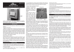
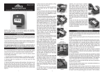
2. Remove the mounting plate from the Smoke Alarm. If it has
been latched, release the tamperproof catch with a small
screwdriver, as shown in figure 7, and slide the alarm from the
mounting plate.
TO REMOVE PUSH
SCREWDRIVER
& PUSH COVER INTO SLOT
AWAY
TO REMOVE PUSH
SCREWDRIVER
INTO SLOT
& PUSH COVER
AWAY
Figure 7: Removing the smoke alarm from the mounting plate
3. Place the base on the ceiling/wall exactly where you want
to mount the unit. With a pencil, mark the location of the two
screw holes.
4. It may be necessary to rotate/resite units to maximise the
radio link signals (see section 5.2). Consequently we advise
to use only one screw initially. Taking care to avoid any electrical wiring in the ceiling, drill one hole through the centre of
one of the marked locations. Push the plastic screw anchors
provided into the drilled hole. Screw in firmly. The second
screw may then be used to securely fix the alarm in place
after the radio link interconnection is verified.
5. Connect the battery to the battery snaps as shown in figure
1a (model Ei405 only).
6. Carefully line up the unit on the base and slide on as shown
in figure 1b. (This connects the batteries in the Ei405TY
Smoke Alarm).
7. Press the test button on each alarm to ensure that the
smoke alarm works (see figure 9).
8.Check the radio link interconnection by holding the test but8