1
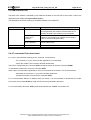
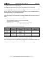
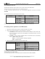
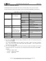
L’esprit Modem
User Guide
GenPro 18e
(GenPro18e)
Reference : EG_GenPro18e_1003_UG_007_UK
Revision :
007
Date :
10/10/2011
S.A. ERCO & GENER – ZI de St. Lambert-des-Levées – BP 30163 – F-49412 SAUMUR Cedex
Tél. : +33 (0)2 41 83 13 00 – Fax : +33 (0)2 41 67 19 20 – www.ercogener.com – [email protected]
SA CAPITAL 200873 € – R.C. SAUMUR B 332 174 820 – SIRET 332 174 820 00032 – NAF 2630Z – TVA Intra : FR 16 332 174 820
EG_GenPro78e_1003_UG_007_UK
Page 2 / 41
Document history
Révision Modifications
Auteur
Date
000
CREATION
F. LE BRETON
27/05/08
001
Added Reset following SIM extraction (paragraph 5.1.4)
F. LE BRETON
27/05/08
F. LE BRETON
30/05/08
F. LE BRETON
10/06/08
002
003
Modified product package sticker page 09 et 11
Update consumptions page 35
Update declaration of conformity page 41
Added consumptions page 34
Modified temperature range page 37
004
Cancelation Error Code table page 25
F. LE BRETON
30/10/08
005
Modified "CPIN" page 16
F. LE BRETON
30/10/09
006
Updating the certificate of conformity.
YST
10/05/11
007
The GenPro 20e SQB becomes the GenPro 18e.
YST
10/10/11
The main modifications in this document compared to its previous version, are easily identifiable on a
monitor by means of the blue text.
Description and non-contractual illustrations in this document are given as an indication only.
ERCO & GENER reserves the right to make any modifications.
EG_GenPro78e_1003_UG_007_UK
Page 3 / 41
CONTENTS
PRESENTATION ................................................................................................................................................ 5 WARNING .......................................................................................................................................................... 6 COPYRIGHT AND DISCLAIMER....................................................................................................................... 6 1 REFERENCES ................................................................................................................................................ 7 1.1 REFERENCE DOCUMENTS ............................................................................................................................... 7 1.2 ABREVIATIONS ............................................................................................................................................... 7 2 PACKING ......................................................................................................................................................... 9 2.1 CONTENTS ..................................................................................................................................................... 9 2.2 PACKING CASE .............................................................................................................................................. 9 2.3 MODEM LABELS ........................................................................................................................................... 10 3 GENERAL PRESENTATION ........................................................................................................................ 11 3.1 PHYSICAL DESCRIPTION ............................................................................................................................... 11 3.2 EXTERNAL CONNECTIONS ............................................................................................................................. 12 3.2.1 Connections ................................................................................................................................... 12 3.2.1.1 GSM antenna connector......................................................................................................... 12 3.2.1.2 4-pin Micro FIT female connector ........................................................................................... 12 3.2.1.3 15-pin Sub HD female connector ........................................................................................... 12 3.2.2 2-wire micro FIT supply cable ....................................................................................................... 13 4 CHARACTERISTICS AND SERVICES ......................................................................................................... 14 5 USING THE MODEM .................................................................................................................................... 15 5.1 STARTING WITH THE MODEM ......................................................................................................................... 15 5.1.1 Mounting the modem ..................................................................................................................... 15 5.1.2 Installation of the modem ............................................................................................................... 15 5.1.3 Communication with the modem ................................................................................................... 16 5.1.4 Extraction of the SIM card.............................................................................................................. 16 5.1.5 Re-initialisation of the modem ....................................................................................................... 17 5.2 RECOMMENDATIONS FOR USING THE MODEM IN VEHICLES .............................................................................. 17 5.2.1 Recommended connection to the battery in a lorry ....................................................................... 17 5.2.2 Technical constraints in lorry ......................................................................................................... 19 5.3 GSM INDICATOR LED .................................................................................................................................. 20 5.4 AT COMMANDS ECHO DEACTIVATED .............................................................................................................. 20 5.5 VERIFYING GSM RECEIVE SIGNAL QUALITY .................................................................................................... 21 5.6 VERIFYING THE PIN CODE ............................................................................................................................ 22 5.7 VERIFYING MODEM REGISTRATION ON THE GSM NETWORK ............................................................................ 22 5.8 MAIN AT COMMANDS (HAYES) .................................................................................................................... 23 5.9 POWERING DOWN THE UNIT .......................................................................................................................... 24 5.10 UPDATING THE MODEM SOFTWARE .............................................................................................................. 24 6 TROUBLE SHOOTING.................................................................................................................................. 25 6.1 RS232 (V24) COMMUNICATION PROBLEM ..................................................................................................... 25 6.2 "ERROR" MESSAGE .................................................................................................................................... 25 6.3 "NO CARRIER" MESSAGE ........................................................................................................................... 26 7 FUNCTIONAL DESCRIPTION ...................................................................................................................... 27 7.1 ARCHITECTURE ............................................................................................................................................ 27 7.2 POWER SUPPLY ........................................................................................................................................... 28 7.2.1 General .......................................................................................................................................... 28 7.2.2 Protection ....................................................................................................................................... 28 7.3 RS232 SERIAL LINK ...................................................................................................................................... 29 Description and non-contractual illustrations in this document are given as an indication only.
ERCO & GENER reserves the right to make any modifications.
EG_GenPro78e_1003_UG_007_UK
Page 4 / 41
7.3.1 General .......................................................................................................................................... 29 7.3.2 Auto-baud mode ............................................................................................................................ 30 7.3.3 Auto-power supply mode through the pin RI ................................................................................. 30 7.3.4 Pins description .............................................................................................................................. 30 7.4 AUDIO ......................................................................................................................................................... 31 7.4.1 Microphone .................................................................................................................................... 31 7.4.2 Loud-speaker ................................................................................................................................. 32 7.5 RESET ....................................................................................................................................................... 32 7.5.1 General .......................................................................................................................................... 32 7.5.2 RESET sequence .......................................................................................................................... 32 8 TECHNICAL CHARACTERISTICS ............................................................................................................... 33 8.1 MECHANICAL................................................................................................................................................ 33 8.2 ELECTRICAL ................................................................................................................................................. 34 8.2.1 Power supply ................................................................................................................................. 34 8.2.2 Audio interface ............................................................................................................................... 35 8.2.3 SIM Interface .................................................................................................................................. 35 8.2.4 GSM/DCS ...................................................................................................................................... 35 8.2.4.1 RF performances .................................................................................................................... 35 8.2.4.2 External GSM Antenna ........................................................................................................... 36 8.2.5 RESET Signal ................................................................................................................................ 36 8.3 ENVIRONMENTAL CHARACTERISTICS.............................................................................................................. 37 8.4 STANDARDS / CONFORMITIES ....................................................................................................................... 37 9 SECURITY RECOMMENDATIONS .............................................................................................................. 38 9.1 GENERAL ..................................................................................................................................................... 38 9.2 SECURITY IN A VEHICLE ................................................................................................................................ 39 9.3 CARE AND MAINTENANCE .............................................................................................................................. 39 9.4 YOUR RESPONSIBILITY .................................................................................................................................. 39 10 RECOMMENDED ACCESSORIES............................................................................................................. 40 11 CLIENT SUPPORT...................................................................................................................................... 40 DECLARATION OF CONFORMITY ................................................................................................................. 41 Description and non-contractual illustrations in this document are given as an indication only.
ERCO & GENER reserves the right to make any modifications.
EG_GenPro78e_1003_UG_007_UK
Page 5 / 41
Presentation
Entirely dedicated to the wireless markets throughout the world, the GenPro 18e allows a simple and rapid
integration of GSM / GPRS connectivity into M2M applications.
The GenPro 18e is a robust, reliable and long life product. Its very compact metal case makes it ideally
adapted to onboard standards.
The GenPro modem is Quad-Band 850/900/1800/1900 MHz and GSM/GPRS Class 10.
The GenPro 18e modem allows the immediate development of onboard high value-added telematic
solutions.
The GenPro 18e provides an external mode of operation, controlled by an external application through an AT
command set (see the ERCO & GENER Commands List).
This document describes the modem and provides the following information:
-
General presentation,
-
Functional description,
-
Available basic services,
-
Installation and use (first level),
-
User-level trouble shooting,
-
Recommended accessories.
For further information, please refer to the following documents:
-
Commands List
-
Application Notes
-
Release Notes
-
Client support (Hot-Line)
Description and non-contractual illustrations in this document are given as an indication only.
ERCO & GENER reserves the right to make any modifications.
EG_GenPro78e_1003_UG_007_UK
Page 6 / 41
Warning
-
TO AVOID ALL RISK OF ELECTROCUTION, DO NOT OPEN THE UNIT
-
THE UNIT CONTAINS NO USER REPAIRABLE COMPONENTS
-
THE UNIT MUST BE RETURNED TO THE MANUFACTURER FOR ANY REPAIRATION
-
THE UNIT MUST NOT BE CONNECTED DIRECTLY TO THE MAINS SUPPLY. PLEASE USE A
SUITABLE EXTERNAL POWER SUPPLY.
In its continuing research into improving its products, ERCO & GENER reserves the right to modify its
products and documentation at any time.
Copyright and Disclaimer
All rights reserved. The reproduction, transfer, distribution or storage of part or the totality of the contents of
this document, in any form, mechanical or electronic, without the prior written authorization from ERCO &
GENER is strictly prohibited.
GenPro 18e is a trademark of ERCO & GENER.
Hayes is a registered trademark of Hayes Microcomputer Product Inc. The names of products and
companies mentioned in this document may be names or trademarks of their respective holders.
Use of certain products or services described in this document may require subscription or a paying
subscription. The availability of certain products or services described in this document can vary according to
the configurations and the materials.
In certain countries, restrictions of use of the equipment may apply. Contact your nearest legally qualified
local government representative for more information.
ERCO & GENER operate a method of continuous development. Consequently, ERCO & GENER reserves
the right to change and improve its products and documentation at any time and without notice.
The contents of this document are provided “as is”. All information contained herein is provided in good faith.
No responsibility can be assumed as to the precision and reliability of the contents of this document. Except
for the applicable obligatory laws, no guarantee in any form, explicit or implicit, including, but without being
limited to it, is granted as to the aptitude for marketing and suitability to a particular use. ERCO & GENER
reserves the right to revise this document or to withdraw it at any time and without notice.
ERCO & GENER cannot in any case to be held responsible for any loss of data or income, as well as
particular damage, incidental, consecutive or indirect.
Description and non-contractual illustrations in this document are given as an indication only.
ERCO & GENER reserves the right to make any modifications.
EG_GenPro78e_1003_UG_007_UK
1 References
1.1 Reference Documents
AT Commands Lists:
EG_GenProxxx_ xxx_1003_CL_000_UK
Software update procedure:
EG_GenProxxx_xxx_1003_UP_000_UK
Documents de reference GSM:
● GSM 07.05.
● GSM 07.07.
1.2 Abreviations
AC
ACM
AMR
AT
BTS
CLK
CMOS
CS
CTS
dB
dBc
dBi
dBm
DC
DCD
DCE
DCS
DSR
DTE
DTMF
DTR
EEPROM
EFR
E-GSM
EMC
EMI
ESD
ETSI
FIT
FR
FTA
GCF
GND
GPIO
GPRS
GSM
HR
I
IEC
Alternative Current
Accumulated Call Meter
Adaptative Multiple Rate
Attention (prefix for modem commands)
Base Transceiver Station
ClocK
Complementary Metal Oxide Semiconductor
Coding Scheme
Clear To Send
Decibel
Decibel relative to the Carrier power
Decibel relative to an Isotropic radiator
Decibel relative to one milliwatt
Direct Current
Data Carrier Detect
Data Communication Equipment
Digital Cellular System
Data Set Ready
Data Terminal Equipment
Dual Tone Multi-Frequency
Data Terminal Ready
Electrically Erasable Programmable Read-Only Memory
Enhanced Full Rate
Extended GSM
ElectroMagnetic Compatibility
ElectroMagnetic Interference
ElectroStatic Discharges
European Telecommunications Standards Institute
Series of connectors (micro-FIT)
Full Rate
Full Type Approval
Global Certification Forum
GrouND
General Purpose Input Output
General Packet Radio Service
Global System for Mobile communications
Half Rate
Input
International Electrotechnical Commission
Description and non-contractual illustrations in this document are given as an indication only.
ERCO & GENER reserves the right to make any modifications.
Page 7 / 41
EG_GenPro78e_1003_UG_007_UK
IMEI
I/O
LED
MAX
ME
MIC
Micro FIT
MIN
MNP
MO
MS
MT
NOM
O
Pa
PBCCH
PC
PCL
PDP
PIN
PLMN
PUK
RF
RFI
RI
RMS
RTS
RX
SIM
SMA
SMS
SNR
SPI
SPL
SPK
SRAM
TCP/IP
TDMA
TU
TUHigh
TX
TYP
UTC
VSWR
International Mobile Equipment Identification
Input / Output
Light Emitting Diode
MAXimum
Mobile Equipment
MICrophone
Family of connectors from Molex
MINimum
Microcom Networking Protocol
Mobile Originated
Mobile Station
Mobile Terminated
NOMinal
Output
Pascal (for speaker sound pressure measurements)
Packet Broadcast Control Channel
Personal Computer
Power Control Level
Packet Data Protocol
Personal Identity Number
Public Land Mobile Network
Personal Unblocking Key
Radio Frequency
Radio Frequency Interference
Ring Indicator
Root Mean Square
Request To Send
Receive
Subscriber Identification Module
SubMiniature version A RF connector
Short Message Service
Signal-to-Noise Ratio
Serial Peripheral Interface
Sound Pressure Level
SpeaKer
Static RAM
Transmission Control Protocol / Internet Protocol
Time Division Multiple Access
Typical Urban fading profile
Typical Urban, High speed fading profile
Transmit
TYPical
Universal Time Clock
Voltage Stationary Wave Ratio
Description and non-contractual illustrations in this document are given as an indication only.
ERCO & GENER reserves the right to make any modifications.
Page 8 / 41
EG_GenPro78e_1003_UG_007_UK
2 Packing
2.1 Contents
The GenPro 18e is supplied with:
- 1 GenPro 18e packing case,
- 1 GenPro 18e modem,
- 2 fixing brackets,
- Instructions Sheet.
- 2-wire cable (Red/Black) with in-line fuse
2.2 Packing Case
Packing case external dimensions:
- Width:
54.5 mm,
- Height:
68 mm,
- Length:
108 mm.
An identification label is attached to the top of the packing case. It contains
- The ERCO & GENER logo,
- The product reference (GenPro 18e),
- CE mark and RoHS compliance mark,
- The IMEI 15-digit bar code.
Identification label dimensions:
- Height:
37 mm,
- Length:
70 mm.
Description and non-contractual illustrations in this document are given as an indication only.
ERCO & GENER reserves the right to make any modifications.
Page 9 / 41
EG_GenPro78e_1003_UG_007_UK
Page 10 / 41
2.3 Modem Labels
One production label, attached to the underside of the modem, provides the following information:
- CE mark,
- Crossed wheelie-bin mark (DEEE standard),
- DC supply (VDC),
- The IMEI 15-digit bar code.
Description and non-contractual illustrations in this document are given as an indication only.
ERCO & GENER reserves the right to make any modifications.
EG_GenPro78e_1003_UG_007_UK
Page 11 / 41
3 General Presentation
3.1 Physical Description
Description of the GenPro 18e modem:
Connector
Micro-Fit 4pins/M
Front side
Connector Sub HD
15pins/F
Rear side
Connector
SMA/F
SIM card cover
GSM LED
Two fixing brackets for attaching the modem to a support:
Brides de fixation
Description and non-contractual illustrations in this document are given as an indication only.
ERCO & GENER reserves the right to make any modifications.
EG_GenPro78e_1003_UG_007_UK
Page 12 / 41
3.2 External connections
3.2.1 Connections
3.2.1.1 GSM antenna connector
The GSM antenna connector is a 50Ω impedance female SMA type.
3.2.1.2 4-pins Micro FIT female connector
This connector allows the connection of an external DC supply.
Pin N°
1
2
3
4
Signal
+VDC
GND
NC
NC
WARNING: pins 3 and 4 are not wired. It is strictly forbidden to connect a supply voltage to these pins – the
modem may be damaged.
3.2.1.3 15-pin Sub HD female connector
This connector provides:
- The serial RS232 link,
- The audio line connection (microphone and loud-speaker),
- The BOOT and RESET signals.
Pin N°
Description
1
Signal detection / Buzzer
2
Data transmission
3
Boot
4
Microphone +
5
Microphone 6
Data reception
7
Data Set Ready
8
Data Terminal Ready
9
Ground
10
Loud Speaker +
11
Clear To Send
12
Request To Send
13
Ring Indicator / 3,8V
14
Reset
15
Loud Speaker Note : the pin 3 is not used.
Circuit (V24 – RS232C)
109 – DS – DCD
103 – ED – TXD
BOOT
MIC2P
MIC2N
104 – RD – RXD
107 – PDP – DSR
108/2 – TDP – DTR
102 – TS – GND
SPK2P
106 – PAE – CTS
105 – DPE – RTS
125 – IA – RI
RESET
SPK2N
I/O
O
I
I
I
I
O
O
I
O
O
I
O
I
O
Description and non-contractual illustrations in this document are given as an indication only.
ERCO & GENER reserves the right to make any modifications.
EG_GenPro78e_1003_UG_007_UK
Page 13 / 41
3.2.2 2-wire micro FIT supply cable
This cable provides power to the modem.
Component
4-pin Micro FIT connector
Cable
Wire
Characteristics
Type : MOLEX
Length ≈ 1.5m
Tinned copper 24 x 0.2 mm
Surface area : 0.75 mm²
Description and non-contractual illustrations in this document are given as an indication only.
ERCO & GENER reserves the right to make any modifications.
EG_GenPro78e_1003_UG_007_UK
Page 14 / 41
4 Characteristics and Services
The GenPro 18e is a class 10 GSM or GSM/GPRS modem intended for asynchronous binary data
transmission, fax Group3 (Class 2), SMS and voice.
The features of the GenPro 18e modem are shown in the table below.
GenPro 18e modem
GSM
- Quad-Bands 850/900/1800/1900 MHz
- ETSI GSM Phase 2+
Classe 4 (2W @ 850 / 900 MHz)
Classe 1 (1W @ 1800 / 1900 MHz)
- SIM Toolkit Release 99
VOICE
- Voice (GSM mode)
- Téléphonie, Emergency call 112
- Full Rate, Enhanced Full Rate, Half Rate et AMR (FR/EFR/HF/AMR)
- Echo cancellation and noise reduction features
- Full Duplex Mains Libres
DATA
- GPRS Multi-Slot Class 10 supported (4Rx / 2Tx)
- PBCCH/PCCCH supported, coding schemes supported : CS1 - CS4
- Circuit de Données asynchrones, transparent et non-transparent 9600 (Standard) à 14400bds (Selon
réseau)
- Compatible Group 3 FAX
- SMS Text, PDU, MT/MO modes and SMS Cell Broadcast
Interfaces
- GSM antenna: SMA-F connector
- Electrical Power: +5.5 à +32 VDC (micro-FIT connector)
- RS232 (300 up to 115200 bds) + Audio through Sub-D 15 pins female connector
- AT commands : GSM 07.05 et 07.07
- SIM reader(SIM 3V – 1,8V)
Supplied accessories
- Fixing brackets (x2)
- 2-wire micro FIT supply cable
Option
- Auto-power supply through the pin RI for external application (*)
(*) Consult us
Description and non-contractual illustrations in this document are given as an indication only.
ERCO & GENER reserves the right to make any modifications.
EG_GenPro78e_1003_UG_007_UK
Page 15 / 41
5 Using The Modem
5.1 Starting with the modem
5.1.1 Mounting the modem
To mount the modem on a support, use the fixing brackets as shown in the diagram below:
Note:
- Must be fixed to a flat
surface.
- Maximum height of the
screw head height: 2 mm
5.1.2 Installation of the modem
To install the modem, it is recommended to perform the following operations with the modem turned off:
- Remove the SIM card cover on the rear side.
- Carefully insert the SIM card into its holder.
- Push the SIM card until the "click", which confirms you the SIM Card is correctly positioned.
- Replace the SIM card cover.
- Connect the GSM antenna to the SMA connector.
- To connect to a DTE, connect the V24 link using the 15-pin Sub HD cable.
- Connect the supply cable to an external regulated DC source (for automobile applications, refer to
chapter 5.2 Recommendations for using the modem in vehicles).
- Connect the supply cable to the modem and turn on the power supply. The GSM LED will light up.
The modem is now ready. Refer to chapter 5.8 Main AT commands (HAYES) for a description of
the commands for configuring and using the modem.
Description and non-contractual illustrations in this document are given as an indication only.
ERCO & GENER reserves the right to make any modifications.
EG_GenPro78e_1003_UG_007_UK
Page 16 / 41
5.1.3 Communication with the modem
Connect the RS232 cable between the DTE (the COM port) and the modem (DCE).
Configure the DTE RS232 port as follows:
▪ Data rate: 9600 bps,
▪ Data size: 8 bits,
▪ Parity: None,
▪ Stop bits: 1,
▪ Flow control: hardware.
Via the DTE (a PC running a communications application such as HyperTerminal), enter the command
AT(CR). The modem should reply with OK.
In the case where no communication can be established with the modem:
▪ Verify the RS232 connexion between the DTE and the modem (DCE),
▪ Verify the configuration of the COM port on the DTE.
Some examples of AT commands which can be sent to the modem once the communication has been
established and verified (these commands are explained in detail later in the document):
▪ AT+CGSN : the modem should reply with a 15 digit number (beginning with "35873000xxxxxxx").
▪ AT+CPIN="xxxx" : enter the code of the SIM card xxxx (if active).
▪ AT+CSQ : verify the GSM signal reception level.
▪ AT+CREG ? : verify the registration of the modem on the network.
▪ ATD<telephone number> : start a voice call.
▪ ATH : hang-up (end of the call).
For further information about these AT commands and their associated parameters, refer to the "Commands
List" from ERCO & GENER.
5.1.4 Extraction of the SIM card
To remove the SIM card from the modem, it is recommended to apply the following instructions, the modem
not power supplied:
- Remove the SIM card cover from the rear side.
- Push on the SIM card (simple pression) up to the "click", allowing its eject.
- Remove carefully the SIM card from its holder.
- Place the SIM card cover.
- Apply a Reset or an ON / OFF to save these operations.
Description and non-contractual illustrations in this document are given as an indication only.
ERCO & GENER reserves the right to make any modifications.
EG_GenPro78e_1003_UG_007_UK
Page 17 / 41
5.1.5 Re-initialisation of the modem
The hardware RESET signal is available on pin 14 of the 15-pin Sub HD connector. The modem is reinitialised when this RESET signal is held at a low level for at least 500µs.
WARNING: This RESET signal should be considered as a means of re-initialising the modem in cases of
emergency only. For further details concerning the RESET of the modem, see the chapter
7.6 RESET.
5.2 Recommendations for using the modem in vehicles
WARNING: The power supply connector on the GenPro 18e must NOT be connected directly to the
battery of a vehicle.
5.2.1 Recommended connection to the battery in a lorry
All Lorries have a circuit breaker outside the cabin. The circuit breaker is necessary for security reasons. For
example, if a fire breaks out in the lorry’s electric box, the driver may cut the power source to avoid further
danger and damage (explosion).
The circuit breaker is connected to the ground of the lorry, usually connected to the fuse box. As such, most
lorry circuit breakers cut the ground connexion rather than the battery power side as shown in the diagram
below:
Description and non-contractual illustrations in this document are given as an indication only.
ERCO & GENER reserves the right to make any modifications.
EG_GenPro78e_1003_UG_007_UK
Page 18 / 41
GenPro 18e
The diagram above shows a recommended connexion, where the modem is connected after the circuit
breaker to the ground of the lorry (or in the fuse box) and NOT directly to the earth of the battery
Description and non-contractual illustrations in this document are given as an indication only.
ERCO & GENER reserves the right to make any modifications.
EG_GenPro78e_1003_UG_007_UK
Page 19 / 41
5.2.2 Technical constraints in lorry
It is highly recommended to NOT connect the modem supply directly the battery but instead to the circuit
breaker. Otherwise the modem may be damaged when the lorry is starting and the circuit breaker is closed.
In this case the ground of the lorry and the ground of the battery will be connected together via the modem
as shown in the diagram below:
GenPro 18e
Example of a forbidden electrical connexion (risk of damage to the modem)
The diagram above shows an electrical connexion which may damage the modem because its ground is
connected directly to the earth of the battery.
In this example, when the circuit breaker is closed, the current flows via the modem and the electrical circuits
in the lorry (dash-board for example). When the lorry’s starter motor is used it could result in the cables and
or the modem being damaged or destroyed.
The internal circuits of the modem are not designed to withstand the high currents associated with starter
motors.
Description and non-contractual illustrations in this document are given as an indication only.
ERCO & GENER reserves the right to make any modifications.
EG_GenPro78e_1003_UG_007_UK
Page 20 / 41
5.3 GSM indicator LED
The state of the modem is indicated by the GSM LED located on the rear side of the modem, close to the
SIM holder (see chapter 3.1 Physical Description).
The table below shows the meaning of the different states of the GSM LED :
GSM LED
ON
OFF
LED activity
LED on fixed
Modem state
The modem is powered, it is ready to function but not
yet recognised by the network; the PIN code has not
yet been entered or the antenna is not connected.
LED flashing
(once every 2
seconds)
The modem is powered, the PIN code is active, the
modem is recognised by the network and is ready to
make or receive a call (Idle mode).
LED flashing
(Once a second)
The modem is powered and currently in communication
(Voice, Data or Fax).
LED off
The modem is not powered or is in the RESET phase.
5.4 AT commands Echo deactivated
If no echo is returned when entering an AT command, it could be that :
- the “Local echo” of your communication application is not activated,
- and/or the modem’s echo function has been deactivated.
The echo is configured by the command ATE and requires a back-up with the command AT&W.
To activate the modem echo, enter the command ATE1.
When using a communication application to send AT commands to the modem, it is recommended to :
- deactivate the "local echo" in your communication application,
- activate the modem echo (enter the command ATE1).
For a communication Machine to Machine with the modem, it is recommended to deactivate the modem
echo (enter the command ATE0) to avoid the CPU receiving redundant responses.
For more information about the ATE command see the ERCO & GENER "Commands List".
Description and non-contractual illustrations in this document are given as an indication only.
ERCO & GENER reserves the right to make any modifications.
EG_GenPro78e_1003_UG_007_UK
Page 21 / 41
5.5 Verifying GSM receive signal quality
The modem will be able to establish a call only if the received GSM signal is of a sufficient level.
The command AT+CSQ will return the reception level (rssi) of the signal sent by the closest GSM Base
Transceiver Station (BTS), as well the receive bit error rate (ber).
When the SIM card is present and the PIN code has been entered, the command AT+CSQ will return the
signal level from the BTS on the subscribed operator network.
When used without the SIM card, this command will simply indicate the closest BTS due to the fact that the
modem cannot identify the current subscription. It is therefore advisable to make this test with the SIM card
present.
To verify the GSM signal quality, perform the following operations:
Using a communication application, enter the command AT+CSQ.
The response is in the following format:
+CSQ: <rssi>,<ber>
where : <rssi> = indicates the reception level,
<ber> = receive bit error rate.
Verify the value <rssi> with the aid of the table below:
<rssi> value
Gain (dbm)
Interpretation
<ber> value
0
-113 dbm
Insufficient
0 to 7
1 to 10
-111 to -95 dbm
Insufficient
11 to 30
-93 to -53 dbm
Sufficient
31 (max)
-51dbm
Perfect
99
Unknown/not detectable
99
Interpretation
See standard ETSI
GSM 05.08
Unknown/not detectable
The GSM modem will function correctly with a minimum <rssi> of between 11 and 15.
Below 10 the signal is insufficient, the modem cannot function depending on the geographical situation or the
mobility of the vehicle. Above 15 the signal is of a sufficient level.
For more information about the AT commands see the "Commands List" from ERCO & GENER.
Description and non-contractual illustrations in this document are given as an indication only.
ERCO & GENER reserves the right to make any modifications.
EG_GenPro78e_1003_UG_007_UK
Page 22 / 41
5.6 Verifying the PIN code
The PIN code is essential in order to make a call or to accept a call from the GSM network.
The PIN code is held on the SIM card and can be modified by the user.
To verify a previously entered PIN code, use a communication application and enter the command
AT+CPIN?
The table below shows the main responses from the modem:
Command
AT+CPIN?
Response
Interpretation
+CPIN: ERROR
The SIM card is absent or unknown
+CPIN: READY
The PIN code is correct
+CPIN: SIM PIN
The PIN code is bad or not yet entered
+CPIN: SIM PUK
The PUK code is required
For more information about the AT commands see the ERCO & GENER "Commands List".
5.7 Verifying modem registration on the GSM network
1. Ensure that a valid SIM card is present in the SIM card reader in the modem.
2. Using a communications application, enter the following AT commands :
a. AT+CPIN=xxxx Enter the PIN code. The user has only 3 attempts to enter the PIN code.
After the third attempt, only the PUK code (supplied by the operator) will allow a new PIN
code to be entered.
b. AT+CREG? Verify the network registration status. The response will be of the following
format : +CREG: <mode>,<stat> where :
<Mode> = un-solicited registration message configuration,
<Stat> = registration status
3. Verify the registration status with the aid of the following table :
Command
AT+CREG?
Response
+CREG: 0,0
+CREG: 0,2
+CREG: 0,1
+CREG: 0,5
Interpretation
The modem is not recognised by the
network.
The modem is searching for a network
operator.
The modem is GSM attached to a local
operator.
The modem is GSM attached to an
operator in roaming mode.
If the modem is not registered, verify the antenna connexion and the receive signal level (see chapter 5.5
Verifying GSM receive signal quality).
For more information about the AT commands see the "Command List" from ERCO & GENER.
Description and non-contractual illustrations in this document are given as an indication only.
ERCO & GENER reserves the right to make any modifications.
EG_GenPro78e_1003_UG_007_UK
Page 23 / 41
5.8 Main AT commands (HAYES)
The table below shows at a quick glance the main AT commands useful for the control of the modem.
For further information concerning the complete command set see the ERCO&GENER "Commands List”.
Table: Main AT commands used with the modem.
Description
AT Command
Enter the PIN code
Verification of GSM
network registration
Response
AT+CPIN=xxxx
OK
PIN code accepted
(xxxx = PIN code)
+CME ERROR: 16
PIN code incorrect (1*)
+CME ERROR: 3
PIN code already entered (1*)
AT+CREG?
+CREG: 0,0
+CREG: 0,2
+CREG: 0,1
+CREG: 0,5
Reception of an
incoming call (2*)
Make a voice call
Interpretation
The modem is not recognised by the
network.
The modem is searching for a
network operator.
The modem is GSM attached to a
local operator.
The modem is GSM attached to an
operator in roaming mode.
ATA
OK
Reply to the call
ATD<telephone
number>;
OK
Communication established
+CME ERROR: 11
PIN code not entered
+CME ERROR: 3
The credit has run out or the
communication has already been
established.
Make an emergency
ATD112;
call (112)
OK
Communication established
Lost communication
NO CARRIER
(IMPORTANT: the ; at
the end of the sequence
specifies a voice call)
Hang-up
ATH
OK
(1*) The command AT+CMEE=1 allows the display of extended error codes. This command may be saved
with the command AT&W.
The command AT%CSTAT=1 allows the display of the change of status of the SIM card (present,
ready…) and to check divers modem states (modem ready after RESET…). This command may be
saved with the command AT&W.
(2*) The command AT+CRC=1 will in the case of an incoming call, display more detailed ring information
indicating the type of call - voice, data or fax. This command may be saved with the command AT&W.
Examples:
For VOICE :+CRING: VOICE
For DATA : +CRING: REL ASYNC
For FAX :
+CRING: FAX
Description and non-contractual illustrations in this document are given as an indication only.
ERCO & GENER reserves the right to make any modifications.
EG_GenPro78e_1003_UG_007_UK
Page 24 / 41
5.9 Powering down the unit
There is no specific AT command to be transmitted to the GenPro 18e modem before removing the power.
5.10 Updating the modem software
So as to be able to benefit from the latest functions of the GenPro 18e, a procedure is used which will
upgrade the software in the modem.
This consists of downloading the software into the internal Flash memory via the RS232 serial link available
on the 15-pin Sub HD connector.
Please refer to the software update procedure document for a detailed description of this procedure.
Description and non-contractual illustrations in this document are given as an indication only.
ERCO & GENER reserves the right to make any modifications.
EG_GenPro78e_1003_UG_007_UK
Page 25 / 41
6 Trouble Shooting
This section describes various problems and their solutions that may be encountered when using the
modem.
6.1 RS232 (V24) Communication problem
If the modem does not respond to any of the AT commands via the RS232 then refer to the table below for a
list of possible causes and solutions.
Table: possible causes and solutions for RS232 communication problems
If the modem...
Returns nothing
Check
Is the modem correctly powered?
Is the serial cable connected at
both ends (PC and Modem)?
Action
Ensure that the modem is connected to an
external regulated power source (5.5V to 32V
DC). See chapter 8.2.1 Power supply.
Verify the connexion of the serial cable.
Is the serial cable correctly cabled Cable the serial cable according to the table in
according to the table in chapter
chapter 3.2.1.3 15-pin Sub HD female
connector.
3.2.1.3 15-pin Sub HD female
connector?
Returns nothing or
random characters
Is the communications terminal
correctly configured on the PC?
Is there another application using
the same port thus creating a
conflict?
Is the modem echo deactivated
and without message reporting?
Ensure that the terminal configuration
corresponds to that of the modem.
Factory configuration :
Speed = 9600 bps
Data bits = 8
Parity = none
Stop bits = 1
Flow control = hardware
Close the conflicting application.
Enter the command ATE1Q0 followed by AT&W
if a backup is required.
6.2 "ERROR" message
The modem returns the message “ERROR” (in response to an AT command) in the following cases :
•
The COM port is not directed to the GenPro 18e but to another modem. Enter the command
ATI1. The response should be Enabler_III.... All other responses indicate a dialog with another
modem. Verify the COM port used in the communications application.
•
The syntax of the AT command is incorrect. Re-enter the command. (Refer to the ERCO &
GENER "Commands List")
•
The syntax of the AT command is correct, but with incorrect parameters :
Description and non-contractual illustrations in this document are given as an indication only.
ERCO & GENER reserves the right to make any modifications.
EG_GenPro78e_1003_UG_007_UK
-
Page 26 / 41
Enter the command AT+CMEE=1 to obtain an error message with its error code instead of a
simple “ERROR” message,
-
Enter again the AT command which previously caused a problem to obtain the error code. In
the case of an error, the response is in the form :
+CME ERROR : <error code>
For further information about the error codes returned by the command AT+CMEE, refer to the ERCO &
GENER "Commands List".
Note : It is strongly recommended to systematically allow the modem to return error codes (enter the
command AT+CMEE=1).
6.3 "NO CARRIER" message
If the modem returns the message "NO CARRIER" after an attempted call (voice or data), check the table
below for a list of possible causes and solutions.
Table : Causes and solutions when the "NO CARRIER " message is returned
Modem returns...
"NO CARRIER"
Check
Action
Is the received GSM signal strong Verify the received signal quality (see chapter
enough?
5.5 Verifying GSM receive signal quality).
Is the modem registered on the
network?
Is the antenna correctly
connected?
Verify network registration (see chapter 5.7
Verifying modem registration on the GSM
network).
Check the GSM antenna installation (see chapter
8.2.6.3 External GSM Antenna for installation
recommendations).
Ensure that the semi-colon (;) been entered
immediately after the telephone number in the
AT command, for example : ATD0123456789;
"NO CARRIER"
(when attempting a
VOICE call)
Has the semi-colon (;) been
entered immediately after the
telephone number in the AT
command?
"NO CARRIER"
(when attempting a
DATA call)
Has the SIM card been configured Ensure that the SIM card is allowed to make data
for data / fax calls?
/ fax calls (check with your SIM card supplier).
Is the selected modulation type
supported by the called number?
Ensure that the selected modulation type is
supported by the called number.
Is the selected modulation type
supported by the network?
Ensure that the selected modulation type is
supported by the network. If not, select a
compatible modulation type with the command
AT+CBST=0,0,1 (1*).
(1*) For further information concerning this command see the ERCO&GENER "Commands List”.
If the modem returns the message "NO CARRIER", use the command AT+CEER to see the extended error
code.
For further information about the error codes returned by the command AT+CEER, refer to the ERCO &
GENER "Commands List".
Description and non-contractual illustrations in this document are given as an indication only.
ERCO & GENER reserves the right to make any modifications.
EG_GenPro78e_1003_UG_007_UK
7 Functional description
7.1 Architecture
Description and non-contractual illustrations in this document are given as an indication only.
ERCO & GENER reserves the right to make any modifications.
Page 27 / 41
EG_GenPro78e_1003_UG_007_UK
Page 28 / 41
7.2 Power supply
7.2.1 General
The modem must be powered (V+BATTERY) by an external regulated DC power source of between 5.5V
and 32V.
The modem’s various internal DC voltages are provided by an internal DC/DC converter.
The correct functioning of the modem cannot be guaranteed if the input voltage (V+BATTERY) falls below
5.5V.
7.2.2 Protection
The modem is protected by an in-line 2.5A / 250V fuse in the power supply cable supplied with the modem.
It also has internal protection against power supply spikes of more than 32V.
Filter guarantees:
Input/output EMI/RFI protection,
Signal smoothing.
Description and non-contractual illustrations in this document are given as an indication only.
ERCO & GENER reserves the right to make any modifications.
EG_GenPro78e_1003_UG_007_UK
Page 29 / 41
7.3 RS232 serial link
7.3.1 General
The RS232 interface provides a level translation (V24/CMOS ⇔ V24/V28) between the GSM module DCE)
and the PC COM port (DTE).
The RS232 interface is protected internally (ESD protection) against external electrostatic spikes.
Filter guarantees:
Input/output EMI/RFI protection,
Signal smoothing.
The following signals are available:
TX data (CT103/TX)
RX data (CT104/RX)
Request To Send (CT105/RTS)
Clear To Send (CT106/CTS)
Data Terminal Ready (CT108-2/DTR)
Data Set Ready (CT107/DSR)
Data Carrier Detect (CT109/DCD) : optional Buzzer output,
Ring Indicator (CT125/RI) / 3.8V : optional 3.8V supply for GenBlue xxe.
RS232 signals
The DSR signal is always present in a high level when the modem is power supplied.
The RS232 interface allows a certain amount of flexibility in the use of its signals. For example, after
configuration (see command AT+IFC) the modem may operate in the 3-wire mode using only the TX, RX
and GND signals. However, the TX, RX, GND, CTS and RTS signals will also be required for GPRS
applications and Xmodem upgrade. This is not the case for the DTR, DSR, DCD and RI signals which may
be not used.
Description and non-contractual illustrations in this document are given as an indication only.
ERCO & GENER reserves the right to make any modifications.
EG_GenPro78e_1003_UG_007_UK
Page 30 / 41
7.3.2 Auto-baud mode
The auto-baud mode allows the modem to automatically detect the transmission speed used by the DTE.
(only from 1200 up to 115200 bps).
The auto-baud mode is controlled by the command AT+IPR. This function is explained in detail in the ERCO
& GENER “Commands List”.
Note: By default, the GenPro 18e is delivered with the RS232 interface configured to 9600 bps, no parity, 8
data bits, 1 stop bit.
It is recommended to prefer a fixed speed to the auto-baud mode.
7.3.3 Auto-power supply mode through the pin RI
An option (not soldered by default) exists allowing the auto-power supply mode in 3.8V, through the pin RI ,
for an external application (the GenBlue 15e for instance).
7.3.4 Pins description
Table: Pins description
Signal
Pin number on Sub
HD connector
I/O
RS232
standard
CTXD/CT103
2
I
TX
Transmit serial data
CRXD/CT104
16
O
RX
Receive serial data
CRTS/CT105
12
I
RTS
Request To Send
CCTS/CT106
11
O
CTS
Clear To Send
CDSR/CT107
7
O
DSR
Data Set Ready
CDTR/CT108-2
8
I
DTR
Data Terminal Ready
CDCD/CT109
1
O
DCD
Data Carrier Detect
CRI/CT125
13
O
RI
CT102/GND
9
Description
Ring Indicator / 3.8V option (*)
Ground
(*) This 3.8V auto-power supply option is not wired by default.
Description and non-contractual illustrations in this document are given as an indication only.
ERCO & GENER reserves the right to make any modifications.
EG_GenPro78e_1003_UG_007_UK
Page 31 / 41
7.4 Audio
The audio interface is a standard interface for connecting a telephone handset (the command AT$VSELECT
enables you to select the handset, please refer to ERCO & GENER "Commands List").
Echo cancellation (see command AT$MICAEC) and noise reduction features are also available to improve
the audio quality in hands-free applications.
ERCO & GENER recommend the use of the following cable: DATA/AUDIO Sub D 9pts Fem / Sub HD 15pts
Male / RJ9 (order code 4404000205) and a telephone handset (order code 3153400000).
Table: Pin identification
SUBD 9 F pin number
SUBD 15 M-HD pin number
1
1
2
6
3
2
4
8
5
9
6
7
7
12
8
11
9
13
RJ9 pin number
1
4
2
10
3
15
4
5
Pin name
DCD/Buzzer
RXD
TXD
DTR
GND
DSR
RTS
CTS
RI/3.8V
Micro +
Speaker +
Speaker Micro -
7.4.1 Microphone
Differential microphone inputs are used to help reduce common–mode and TDMA noise. They are ESD
protected.
An electret type microphone (0.5 mA / 2 Volts) may be connected directly to these inputs allowing the
connexion of a telephone handset.
The microphone impedance is approximately 36 kΩ.
The gain of the microphone input may be internally adjusted by a differential amplifier and may be defined by
using the command AT+PREAMP (see the ERCO & GENER “Commands List”).
The amplifier has a gain of 25.6 dB and a Bias generator providing an external voltage of 2 or 2.5V for the
Bias microphone.
Table: Pins description
Signal name
Pin number Sub HD
Connector
I/O
Type
Description
CMIC2P
4
I
Analogue
Microphone +ve
CMIC2N
5
I
Analogue
Microphone -ve
Description and non-contractual illustrations in this document are given as an indication only.
ERCO & GENER reserves the right to make any modifications.
EG_GenPro78e_1003_UG_007_UK
Page 32 / 41
7.4.2 Loud-speaker
Differential outputs are used to help reduce common–mode and TDMA noise.
The loud-speaker may be connected directly to the output pins.
Table: Pins description
Signal name
Pin number Sub HD
Connector
I/O
Type
Description
CSPK2P
10
O
Analogue
Loud-speaker +ve
CSPK2N
15
O
Analogue
Loud-speaker -ve
7.5 RESET
7.5.1 General
A low level input on this pin (over at least 10ms) allows a forced emergency hardware RESET of the modem.
In this case it acts as an input. It must be driven by an open-collector circuit.
•
PIN 14 (RESET) AT 0, TO RESET THE MODEM,
•
pin 14 (RESET) at 1, normal operating mode.
This pin may also be used to provide a RESET to an external equipment. In this case it acts as an output. If
an external RESET is not required it may be left unconnected.
Table: Pin description
Signal
Pin number on Sub HD
Connector
I/O
Type
Description
RESET
14
I/O
SCHMITT
Reset Modem
WARNING: This signal must only be used in a case of emergency. A software RESET is always
preferable to a hardware RESET. It is strongly unadvised to execute a RESET whilst in
communication or dialogue without having first detached from the network operator
7.5.2 RESET sequence
To activate the emergency RESET sequence, the RESET signal may be pulled to a low level for at least
10ms.
After the modem has been RESET, if a SIM card is present in the reader there will be a delay whilst it is
initialised before being accessible.
Description and non-contractual illustrations in this document are given as an indication only.
ERCO & GENER reserves the right to make any modifications.
EG_GenPro78e_1003_UG_007_UK
Page 33 / 41
8 Technical Characteristics
8.1 Mechanical
Table: Mechanical characteristics
Dimensions
Overall Dimensions
Weight
Volume
Case
Ingress Protection
73 x 54.5 x 25.5 mm (excluding connectors)
90 x 54.5 x 25.5 mm
≈ 88 grams (modem only)
< 197 grams (modem + fixing brackets + cables)
101.5 cm³
Extruded aluminium
IP31
The illustration below indicates the dimensions (in mm) of the modem showing the clearances necessary for
installation.
Description and non-contractual illustrations in this document are given as an indication only.
ERCO & GENER reserves the right to make any modifications.
EG_GenPro78e_1003_UG_007_UK
Page 34 / 41
8.2 Electrical
8.2.1 Power supply
Table: Voltage range and power consumptions
5.5V to 32V DC (GSM or DCS or GPRS)
Operating voltage range
- GSM 900 MHz : 90mA @ 12V in communication
Average power consumptions
- GSM 1800 MHz : 80mA @ 12V in communication
- Idle mode : 12mA @ 12V
Note : The modem is permanently powered once the power supply is connected.
The table below indicates the consequences of over and under-voltage on the modem.
Table: Effects of a power supply defect
If the voltage :
Then :
falls bellow 5.5V
GSM and GPS communications cannot be
guaranteed.
goes above 32V
(transient peaks)
The modem guarantees its own protection.
goes above 32V
(continuous over-voltage)
The modem is short-circuited by an internal varistor.
The modem is then protected by the in-line fuse.
The table below indicates the power supply consumption of the modem without the RS232 connected.
Table: Consumption (1*) without RS232 connected
CONDITIONS
T=25°C and 3V SIM card
Idle mode (2*)
In communication GSM
1RX/1TX
Power (2W/1W)
In communication GPRS CL10
3RX/2TX
Power (2W/1W)
During TX bursts
Power (2W/1W)
@ 5,5V
@ 12V
@ 24V
@ 32V
@ 5,5V
@ 12V
@ 24V
@ 32V
@ 5,5V
@ 12V
@ 24V
@ 32V
@ 5,5V
@ 12V
@ 24V
@ 32V
E-GSM/GPRS 900MHz
I Nom.(mA)
17,5
12
11
8,5
180
90
46.5
35
329
167
86.5
65
1250
630
318
246
E-GSM/GPRS 1800MHz
I Nom.(mA)
17,5
12
11
8,5
156
80
39.5
30
275
140
72.5
54
1000
506
252.5
197
(1*) The power consumption may vary by 5% over the whole operating temperature range (-20 °C to +60 °C)
(2*) Idle mode: modem is registered on the network but not in communication.
Description and non-contractual illustrations in this document are given as an indication only.
ERCO & GENER reserves the right to make any modifications.
EG_GenPro78e_1003_UG_007_UK
Page 35 / 41
8.2.2 Audio interface
The audio interface is accessible via the 15-pin Sub HD connector (see chapter 7.4).
Table: Characteristics of the audio interface on the 15-pin Sub HD connector
Mic Input
Parameter/Conditions
Maximum Input Range –
Mic(+) to Mic(-)
Inputs 3 dBm0 (Max. digital
sample amplitude when PGA
gain set to 0 dB)
Differential MIC
Nominal Ref. Level –
Mic(+) to Mic(-)
Min
Differential Input Resistance –
Mic(+) to Mic(-)
Differential MIC,
MICAMP gain = 25.6 dB
Microphone Pre-Amplifier Gain
Differential MIC
Typ
Max
32.5
mV
RMS
-10
dBm0
36
kΩ
25.6
dB
8.2.3 SIM Interface
Table: SIM card characteristics
SIM Card
Units
3 V or 1.8 V
8.2.4 GSM/DCS
8.2.4.1 RF performances
The RF performances are compliant with the ETSI GSM 05.05 recommendation.
The RF performances for receiver and transmitter are given in the table below.
Table: Receiver and Transmitter RF performances
Receiver
850MHz/900MHz sensitivity
- 106 dBm, GPRS Coding Scheme 1 (CS1)
1800MHz/1900MHz sensitivity
- 106 dBm, GPRS Coding Scheme 1 (CS1)
Transmitter
Transmit Power (Power Class1 - 850/900) at ambient
temperature
33 dBm +/- 2 dB @ antenna connection
Transmit Power (Power Class4 - 1800/1900) ) at
ambient temperature
30 dBm +/- 2 dB @ antenna connection
Description and non-contractual illustrations in this document are given as an indication only.
ERCO & GENER reserves the right to make any modifications.
EG_GenPro78e_1003_UG_007_UK
Page 36 / 41
8.2.4.2 External GSM Antenna
The external GSM antenna is connected to the modem via the SMA/M connector. It must have the characteristics listed in the table below.
Table: External GSM antenna characteristics
Antenna frequency range
850/900/1800/1900 MHz
Impedance
50 Ohms nominal
DC Impedance
0 Ohm
Gain (antenna + cable)
0 dBi (in a minimum direction)
VSWR (Rx max TX max)
1.5:1
Polarisation
Linear
Note: See chapter 10 Recommended Accessories for GSM antenna recommended by ERCO & GENER.
8.2.5 RESET Signal
Typical Reset Connection
Table : RESET signal operating conditions
Parameter
Condition
VIL
Input Voltage – Low or float
VIH
Input Voltage – High
1.36
IPU
Internal Pull-Up Resistor
-40
IIL
Current sink
Reset Pulse Duration
Min.
Typ.
-31
Max.
Unit
0.58
Vdc
1.95
Vdc
-15
µA
-2.0
mA
10
Description and non-contractual illustrations in this document are given as an indication only.
ERCO & GENER reserves the right to make any modifications.
mS
EG_GenPro78e_1003_UG_007_UK
Page 37 / 41
8.3 Environmental characteristics
To ensure the correct operation of the modem, the limits listed in the table below should be respected.
Table: Environmental characteristics
Operating temperature
-20 °C to +60 °C
Storage temperature
-30 °C to +85 °C
Operating humidity without condensation
HR < 70% @ +55°C
Atmospheric pressure
normal
8.4 Standards / Conformities
The product conforms to the following requirements:
•
R&TTE 1999/5/EC Directive,
•
Regulations of standard ETSI EN 301 489-7 (02),
•
ROHS compliant : directive 2002/95/CE
•
2002/96/CE DEEE (crossed out wheelie bin).
The following mark is visible on the underside of the unit:
Description and non-contractual illustrations in this document are given as an indication only.
ERCO & GENER reserves the right to make any modifications.
EG_GenPro78e_1003_UG_007_UK
Page 38 / 41
9 Security Recommendations
9.1 General
It is important to follow the specific regulations for the use of radio operator equipment, in particular the
possible risks of radio frequency interference (RFI). Please follow carefully the security advice given below.
Turn off your GSM modem:
•
On an aircraft. The use of cellular telephones can endanger the operations of the plane, disturb the
cellular network and is illegal. The non-observance of this instruction can lead to the suspension of
cellular telephone services as well as a fine.
•
At a refuelling station.
•
In any area with a potentially explosive atmosphere which could lead to an explosion or a fire.
•
In hospitals and similar places where medical equipment may be in use.
Restrictions of use of radio operator equipment in:
•
Fuel depots.
•
Chemical factories.
•
Locations where demolition is under way.
•
Other places where signs indicate that the use of cellular telephones is prohibited or dangerous.
•
Other places where you should normally turn off the engine of your vehicle.
There can be a danger associated with the use of your GSM modem close to insufficiently protected medical
devices such as acoustic apparatus and pacemakers. Consult the manufacturers of medical equipment to
determine if it is adequately protected.
The use of your GSM modem close to other electronic equipment may also cause interference if the
equipment is insufficiently protected. Observe all the manufacturer’s warnings and recommendations for the
equipment.
The modem is designed to be used with “fixed” and “mobile” applications:
•
“Fixed application”: The GSM modem is physically connected to a site and it is not possible to be
easily moved to another site.
•
“Mobile application”: The GSM modem is designed to be used in various places (other than fixed)
and is intended for use in portable applications.
Description and non-contractual illustrations in this document are given as an indication only.
ERCO & GENER reserves the right to make any modifications.
EG_GenPro78e_1003_UG_007_UK
Page 39 / 41
9.2 Security in a vehicle
Do not use your GSM modem whilst driving a vehicle, unless equipped with a correctly installed earpiece/hands-free kit.
Respect the national regulations for the use of cellular telephones in vehicles. Road safety is always a
priority.
An incorrect installation of a GSM modem in a vehicle could cause incorrect operation of the electronics of
the vehicle. To avoid such problems, ensure that the installation is carried out by a qualified person. At the
time of the installation, verify the electronic protection system of the vehicle.
The use of an apparatus to activate the headlights or the horn of a vehicle on a public highway is not
authorized.
9.3 Care and maintenance
The suggestions below will help you to look after and preserve this product for many years.
•
Do not expose the modem to the extreme environments such as a high temperature or a high
humidity content.
•
Do not use or store the modem in dusty or dirty places.
•
Do not open or disassemble the modem. ALL WARRANTIES ARE VOID IF THE PRODUCT IS
OPENED, ALTERED, AND/OR DAMAGED.
•
Do not expose the modem to liquids. It is not impermeable.
•
Avoid dropping, striking, or shaking the modem violently.
•
Do not place the modem near computer disks, credit or voyage cards or other magnetic media. The
information contained on the discs or the cards can be affected by the modem.
•
The use of third party equipment or accessories, not made or authorized by ERCO & GENER can
cancel the guarantee.
9.4 Your responsibility
This modem is under your responsibility. Treat it with care. It is not a toy. Install it in a secure place out of the
reach of children.
Make a careful note of your PIN and PUK codes. Familiarize yourself with the modem and its functions. Use
the security functions to prevent unauthorized use and/or theft.
Description and non-contractual illustrations in this document are given as an indication only.
ERCO & GENER reserves the right to make any modifications.
EG_GenPro78e_1003_UG_007_UK
Page 40 / 41
10 Recommended Accessories
The accessories recommended by ERCO & GENER for use with the GenPro modem are shown on our
Internet site in the section Products > Accessories. For more information, contact our sales department.
11 Client support
ERCO & GENER ensures customer support for all sold modems. As such you will have access to:
The latest version of this document,
The product’s brief commercial description,
The latest OS User Guides,
Conformity certificates,
Application notes.
Description and non-contractual illustrations in this document are given as an indication only.
ERCO & GENER reserves the right to make any modifications.
L’esprit Modem
DECLARATION OF CONFORMITY
Manufacturer: ERCO & GENER
Address:
Rue des Petites Granges
Z.I. de Saint Lambert des Levées
B.P. 30163
49412 SAUMUR CEDEX – France
Website:
http://www.ercogener.com
declares that the products :
GenPro 18e
Name:
Type:
Modem
Complies with :
- R&TTE 1999/5/EC Directive,
- EN301489-1:V1.8.1
- EN301489-7:V1.3.1
- §6.5, §6.6, §6.8 and §6.9 of the 2004/104/CE directive
- EN 301 511 v9.0.2
- EN 60950-1:2006 + A11:2009
- EN50385 :2002
- ROHS Compliant : Directive 2002/95/CE
- "REACH" N°1907/2006- R&TTE 1999/5/EC Directive
The corresponding markings appear under the appliance.
Saumur, January 10th 2011
Charles CHAUSSONNIER
Managing Director
S.A. ERCO & GENER – ZI de St. Lambert-des-Levées – BP 30163 – F-49412 SAUMUR Cedex
Tél. : +33 (0)2 41 83 13 00 – Fax : +33 (0)2 41 67 19 20 – www.ercogener.com – [email protected]
SA CAPITAL 200873 € – R.C. SAUMUR B 332 174 820 – SIRET 332 174 820 00032 – NAF 2630Z – TVA Intra : FR 16 332 174 820