1
Owner's
ManuaJ
®
42-inch
Universal
Tow Behind
ModeJ No, 486,243293
,,
,,
•
,,
,,
CAUTION:
Before using this product, read
this manuaU and follow aH Safety
RuUes and
Operating
Instructions.
IMPORTANT
Safety
AssembLy
Operation
Maintenance
Parts
- READ THiS FIRST!!!
For Missing Parts or AssembUy Questions
PUease Call 866-576-8388
Mon.-Fri. 7 am - 5 pm CST.
FAX 217-728-2032
or e-maiU info@ a aji-fab.com
Missing parts will be sent UPS in 24 hours directly to your home.
Sears,
Roebuck and Co., Hoffman
Estates, IL 60179 U.S.A.
www.sears.com/craftsman
PRINTED iN U.S.A.
FORM NO. 49638 (1/05)
TABLE OF CONTENTS
WARRANTY ................................................................
2
SAFETY RULES .......................................................
3-4
CARTON CONTENTS .................................................
5
ASSEMBLY ...............................................................
6-8
WiRiNG DIAGRAM .....................................................
8
OPE RATION ...........................................................
9-13
LIMITED WARRANTY
ON CRAFTSMAN
MAINTENANCE ...................................................
14-15
SERVICE AND ADJUSTMENT ............................ 16-17
STORAGE .................................................................
18
REPAIR PARTS LISTS ......................................... 20-22
SLOPE GUIDE ..........................................................
23
PARTS ORDERING/SERVICE .................... Rear Cover
POWERED TRACTOR ATTACHMENTS
For one (1) year from the date of purchase, if this Craftsman Equipment is maintained, lubricated and tuned up
according to the instructions in the owner's manual, Sears will repair or replace free of charge any parts found to
be defective in materia! or workmanship. Warranty service is available free of charge by returning your Craftsman
equipment to your nearest Sears Service Center. In=home warranty service is available but a trip charge will apply.
This Warranty applies only while this product is in the United States.
This Warranty does not cover:
Expendable items which become worn during normal use, such as spark plugs, air cleaners, belts, and oil
filters.
Tire replacement or repair caused by punctures from outside objects, such as nails, thorns, stumps, or glass.
Repairs necessary because of operator abuse, including but not limited to, damage caused by impacting
objects that bend the frame or crankshaft, or over=speeding the engine.
Repairs necessary because of operator negligence, including but not limited to, electrical and mechanical
damage caused by improper storage, failure to use the proper grade and amount of engine oi!, or failure to
maintain the equipment according to the instructions contained in the owner's manual.
Engine (fuel system) cleaning or repairs caused by fuel determined to be contaminated or oxidized (stale). In
general, fuel should be used within 30 days of its purchase date.
Equipment used for commercia! or rental purposes.
LIMITED WARRANTY ON BATTERY
For ninety (90) days from date of purchase, if any battery included with the equipment proves defective in material
or workmanship and our testing determines the battery will not hold a charge, Sears wil! replace the battery at no
charge. Warranty service is available free of charge by returning your Craftsman equipment to your nearest Sears
Service Center. In-home warranty service is available but a trip charge wil! apply. This Warranty appties only while
this product is in the United States.
TO LOCATE THE NEAREST SEARS SERVICE CENTER OR TO SCHEDULE SERVICE,
SIMPLY CONTACT SEARS AT 1=800-4=MY=HOME.
This warranty gives you specific legal rights, and you may also have other rights, which vary from state to state.
SAFETY
Safe Operation
Practices
RULES
for Tow Behind Mowers
WARNING: This cutting machine is capable of amputating hands and feet and throwing objects. Failure to
observe the following safety instructions could result in serious injury or death.
L
,
,
,
,
,
,
,
GENERAL OPERATION
Read, understand and follow all instructions in the
manual and on the machine before starting.
Read this operator's manual carefully. Become
familiar with the controls and know how to operate
your mower properly.
Only allow responsible adults who are familiar with
the instructions to operate the machine.
Clear the area of objects such as rocks, toys, wire,
etc., which could be picked up and thrown by the
blade.
Be sure the area is clear of other people before
mowing. Stop machine if anyone enters the area.
Never carry passengers.
Do not mow in reverse unless absolutely
necessary. Always look down and behind before and
during backing.
Be aware of the mower discharge direction and do
not point it at anyone. Do not operate the mower
without the guard in place.
Slow down before turning.
Never leave a running machine unattended. Always
turn off blades and stop engine.
Turn off blades when not mowing.
Mow only in daylight or good artificial light.
Do not operate the machine while under the
influence of alcohol or drugs.
Watch for traffic when crossing or operating near
roadways.
Use extra care when loading or unloading the
machine into a trailer or truck.
Do not attempt to operate your tractor or mower
when not in drivers seat.
Disengage power to mower and stop engine when
transporting or when not in use.
Exercise special care when mowing around fixed
objects in order to prevent the blades from striking
them. Never deliberately run tractor or mower onto
or over any foreign object.
Use mower only as the manufacturer intended and
as described in this manual.
Do not operate mower if it has been dropped or
damaged in any manner. Always have damage
repaired before using your mower.
Always wear safety glasses or eye shields when
starting and while using your mower.
Dress properly. Do not operate mower when
barefoot or wearing open sandals. Wear only solid
shoes with good traction when mowing.
Always make cutting height adjustments before
starting your mower. Never attempt to do this while
the engine is running.
Keep your eyes and mind on your mower and the
area being cut. Do not let other interests distract
you.
Do not put hands or feet near or under rotating
parts. Keep clear of the discharge opening at all
times.
,
Before cleaning, inspecting, or repairing your
mower, stop the engine and make absolutely sure
the blade and all moving parts have stopped. Then
disconnect the spark plug wire and keep it away
from the spark plug to prevent accidental starting.
Do not operate your mower if it vibrates
abnormally. Excessive vibration is and indication of
damage; stop the engine, safely check for the cause
of vibration and repair as required.
Never operate your mower without proper guards,
plates or other safety devices in place.
H.
SLOPE OPERATION
Slopes are a major factor related to toss-of-control and
tip-over accidents, which can result in severe injury or
death. All slopes require extra caution, if you feel uneasy
on it, do not mow it.
DO:
Mow up and down slopes, not across.
Remove obstacles such as rocks, tree limbs, etc.
Watch for holes, ruts or bumps. Uneven terrain could
overturn the machine. Tall grass can hide obstacles.
Use slow speed. Choose a low gear so that you will
not have to stop or shift while on the slope.
Follow the manufacturer's recommendations for
wheel weights or counterweights to improve stability.
Keep all movement on the s!opes stow and gradual
Do not make sudden changes in speed or direction.
Avoid starting or stopping on a slope, if tires lose
traction, disengage the blades and proceed slowly
straight down the slope.
DO NOT:
Do not turn on slopes unless necessary, and then
turn stowly and gradually downhill, if possible=
Do not mow near drop-offs, ditches or
embankments. The mower could suddenly turn over
if a wheel is over the edge of a cliff or ditch, or if an
edge caves in.
Do not mow on wet grass. Reduced traction could
cause sliding.
Ill.CHILDREN
Lookforthissymbolto pointout
importantsafetyprecautions.
It
meansCAUTION!!!
BECOME
ALERT!!!
YOURSAFETYIS
INVOLVED.
Tragicaccidentscanoccurif theoperatoris notalertto
thepresenceofchildren.Childrenareoftenattractedto
themachineandthemowingactivity.Neverassumethat
childrenwillremainwhereyoulastsawthem.
*
*
*
*
*
*
Keepchildrenoutofthemowingareaandunderthe
watchfulcareofanotherresponsible
adult.
Bealertandturnmachineoff ifchildrenenterthe
area.
Beforeandwhenbacking,lookbehindanddownfor
smallchildren.
Nevercarrychildren.
Theymayfalloffandbe
seriouslyinjuredor interfere
withsafemachine
operation.
Neverallowchildrentooperatethemachine.
Useextracarewhenapproaching
blindcorners,
shrubs,treesor otherobjectsthatmayobscure
vision.
CAUTION:Alwaysdisconnect
spark
plugwireandplacewirewhereit
cannotcontactsparkpluginorder
topreventaccidenta!
startingwhen
settingup,transporting,
adjustingor
makingrepairs.
IV. SERVICE
*
*
*
*
*
*
*
*
*
Useextracarein handlinggasolineandotherfuels.
Theyareflammable
andvaporsareexplosive.
* Useonlyanapproved
container.
* Neverremovegascaporaddfue!withthe
enginerunning.
* Allowenginetocoolbeforerefueling.Donot
smokenearor whileoperating
mower.
* Neverrefuelthemachineindoors.
* Neverstorethemachineorfuelcontainerinside
a roomwherethereis anopenflame,suchas
witha gaswaterheater.
Neverruna machineinsidea closedarea.
Keepnutsandbolts,especiallybladeattachment
nuts,tightandkeepequipment
in goodcondition.
Nevertamperwithsafetydevices.Checktheir
properoperationregularly.
Keepmachinefreeofgrass,leavesorotherdebris
build-up.
Cleanoilor fuelspillage.
Allowmachineto
coo!beforestoring.
Stopandinspecttheequipment
if youstrikean
object.Repair,if necessary,
beforerestarting.
Nevermakeadjustment
or repairswiththeengine
running.
Mowerbladesaresharpandcancut.Wrapthe
blade(s)or weargloves,anduseextracautionwhen
servicingthem.
Checkbrakeoperation
frequently.
Adjustand
serviceas required.
4
Please read and keep this manual The instructions will
enable you to assembJe and maintain your Power
Mower propedy. Atways observe the "Safety Rules."
Record serial number and date of purchase in space
provided below.
MODEL
NUMBER:
486.243293
SERIAL
NUMBER:
DATE OF
PURCHASE:
The model and serial numbers will be found on a
pKateattached to the right side of the Drive Housing.
You should record both serial number and date of
of purchase and keep in a safe place for future
reference.
C
PARTS PACKED SEPARATELYtN
WARNING: This unit is equipped with an
internal combustion
engine and should
not be used on or near any unimproved
forest-covered
or grass-covered
land
unless the engine's exhaust system is equipped
with a spark attester meeting applicable local or
state laws (if any). If a spark attester is used, it
shoumd be ma#_tained in effective working order by
the operator.
mnthe state of California the above is required by
law {Section 4442 of the California Public Resources
Code). Other states may have similar laws. Federal
_aws apply on federal _ands° A spark attester for the
muffler is available through your nearest Sears
Authorized Service Center.
PRODUCT
SPECIFICATIONS
HORSEPOWER:
10.5
DISPLACEMENT:
21 CU. }N.
GASOLINE TYPE:
UNLEADED REGULAR
OIL TYPE (APFSF/SG):
SAE 30 (ABOVE 32°F)
SAE 5W-30 (BELOW 32°F)
Of L CAPACITY:
28 OUNCES
SPARK PLUG:
(GAP: .030")
VALVE CLEARANCE:
INTAKE: .004 o .006 gN.
EXHAUST: .004 o .006 IN.
BLADE BOLT TORQUE
35_40 FT. LBS.
TIRE PRESSURE
10 PSI
WIDTH OF CUT
42 INCHES
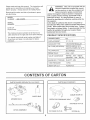
CARTON
CRATE
PARTS BAG CONTENTS
CABLE GUIDE (2)
PARTS BAG
MOWER DECK
OPERATOR PRESENCE
SEAT
3t8 CABLE CLIP (3)
HITCH ASSEMBLY
"_!_
1/2 CABLE CLIP (3)
_SCREW
(3)
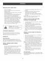
REMOVING
UNmT FROM CRATE
Remove top boards.
Remove two Bolts from front of crate which hold
shipping anchors.
Remove two Bolts from bottom at rear of crate which
•
hold shipping anchors.
Remove Hitch Assembly and Parts Bag from crate.
Remove Roller Bolt from Front Roller, Remove
shipping anchors and reinstall Roller Bolt.
Remove Nuts from Height Adjustment Straps and
remove shipping anchors from each side of mower.
Reinstall Nuts to Height Adjustment Straps, then
loosen 1/4 turn to allow straps to pivot freely.
Check all loose parts and bag contents against
Crate Contents and Bag Contents illustration on
page 5. If any part is missing or damaged contact
the store where you purchased the unit.
CAUTION: Before starting to
assemble mower, remove spark plug
wire from plug of mower engine.
OPERATOR
Assemble a 3/8 Flat Washer onto a 3/8-16 x 2-1/2
Hex Bolt.
o
insert Bolt and Washer through slot of Rear
Quadrant and hole in Towbar Tube.
o
Secure tightly with 3/8-16 Lock Nut then loosen
Nut 1/4 turn to allow tube to pivot freely inside Rear
Quadrant.
NOTE: Towbar Tube must pivot freely inside Rear
Quadrant when latch is pulled from notch.
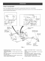
mNSTALL CLUTCH CABLE AND WIRE
HARNESS TO TOWBAR TUBE.
*
*
o
*
Unwrap the Wire Harness and the Clutch Cable from
around the Engine.
Lay the Clutch Cable along the left side of the
Towbar Tube and lay the Wire Harness along the
right side of the Towbar Tube.
install three 3/8" Cable Clips on the Clutch Cable
and three 1/2" Cable Clips onto the Wire Harness.
Align all six Cable Clips with the holes in the Towbar
Tube and secure them with three #10 Self-Tapping
Screws.
ORiENTATiON
When right and left are mentioned in this manual, it
means your right and your left when you are seated
behind the wheel in the operating position.
ENGINE
*
OIL
CABLE
TO THE HUTCH
Remove the 1/4" Lock Nut and 1/4" x 3/4" Bolt from
the Clutch Cable Eyelet,
Screw one 5/16" Nut off the Clutch Cable Housing
and onto the bare cable wire, Screw the second
5/16" Nut all the way onto the Clutch Cable Housing,
Insert the C!utch Cable Eyelet through the slotted
hole in the Cable Anchor on the Hitch Assembly,
NOTE: The loose 5/16" Nut on the cable wire must be
cocked at an angle to fit through the slotted hole,
*
Fasten the Clutch Cable Eyelet to the Clutch Lever,
reusing the 1/4" x 3/4" Hex Bolt and 1/4" Lock Nut,
Tighten the 1/4" Lock Nut securely and then loosen
approximately two turns to allow the cable to pivot
freely on the bolt,
*
Screw the loose 5/16" Nut back onto the Clutch
*
VERY IMPORTANT:
Engine must be filled with oi! before operation. See
OIL & FUEL RECOMMENDATIONS in engine Owner's
Manual for correct filling instructions and oi! fit! capacity.
INSTALL TOWBAR
QUADRANT
mNSTALL CLUTCH
ASSEMBLY
TUBE TO REAR
Cut and remove the Plastic Tie which holds the Wire
Harness and the Clutch Cable to the Rear
Quadrant. (See Fig. 1)
Remove two 3/8 Bolts, two 3/8 Lock Nuts and one
3/8 Flat Washer from the rear of the Towbar Tube.
Place tube into Rear Quadrant, align holes, insert
3/8-16 x 2-1/2 Hex Bolt through rear hole of tube.
Secure tightly with 3/8-16 Lock Nut then loosen
Nut 1/4 turn to allow tube to pivot freely inside Rear
Quadrant.
Cable Housing, Use the 5/16" Nuts to adjust the
cable to the proper tension,
VERY iMPORTANT
See DRIVE TENSION on page 16 in the SERVICE AND
ADJUSTMENTS Section of this manual for proper Clutch
Cable adjustment.
ONtOFF
SWITCH
114"
RING
-1
NUT
COND
RING NUT
©
t_
I/
il
©
//
n
u
If
Ii
II
t
#!0
BOLT 3/8 X 2--112
3/8 FLAT WASHER
3/8 CABLE
1/2 CABLE
SELF
TAPPING
SCREW
CUP
_£_
I
SWITCH
MOUNTING
BRACKET
(3)_,,._
CLIP
CLUTCH
CABLE
CABLE
REAR
QUADRANT
/S;_._
TOW BAR TUBE
WIRE
318 LOCK
HARNESS
HITCH
ASSEMBLY
NUT
BOLT
CABLE EYELET
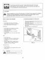
INSTALL THE WIRE HARNESS
ON/OFF SWITCH
MOWER
CLUTCH
AND THE
Slide the Wire Harness under the Cable Anchor of
the Hitch Assembly.
•
Connect two 1/4 Female Spade Connectors from the
Wire Harness to the prongs of the ON/OFF Switch.
Insert the Seat Switch Plug of the Wire Harness into
the Hitch Assembly, Pulling it up and through the
right top side of the Switch Mounting Bracket.
•
Remove one Ring Nut from the ON/OFF Switch and
adjust the second Ring Nut 1/4 Inch from the top of
the threads.
Insert the ON/OFF Switch up through the Switch
Mounting Bracket and secure it by reinstalling the
Ring Nut.
NOTE: The notch in the threads of the ON/OFF Switch
must face toward the "ON" of the ON/OFF Switch Decal
to insure proper ON/OFF control.
1/4 X 3t4
H_TCH
ASSEMBLY
BLADE
LEVER
SWITCH
MOUNTING
BRACKET
CLUTCH CABLE
HOUSING
•
CABLE
AN(
G,
SWITCH
RING NUT
NUT
5/16(2)
SEAT SWITCH
CONNECTOR
CABLE
GUIDE
-J_
WiRE
HARNESS
FiG. 1
LOCK NUT
OPERATOR
INSTALL OPERATOR
TRACTOR
PRESENCE SEAT
PRESENCE
SEAT TO
CABLE GUIDE
Your Mower is equipped with and Operator Presence
Seat to provide for your safety. The Operator Presence
Seat must be installed on the seat of the tow vehicle
and must be plugged in to the Wire Harness of the
Mower for proper operation of this unit.
NOTE: In order to sta4 the mower _
you must
have the Operator Presence Seatplugged into the Wire
Harness of the Mower and the Mower Blade Clutch
Lover in the disengaged position. In order to en a e the
Blades You must be seated on the Tow Vehicle
and on the Operator Presence Seat.
SEAT
WIRE
•
CONNECTOR
SEAT STRAPS
o
FJGo IA
,,
o
WiRiNG
SAFETY
SEAT
Place the Operator Presence Seat on the Tractor
Seat with the Wire toward the bottom and secure
with the seat strap. (See Fig. 1A)
Lift Tractor Seat and install a cable guide in the
middle of the Tractor rear fenders,
P_ace Operator Preseace Seat Wire into Cable
Guide with the connector toward the rear so as to
connect with the Seat Switch Plug of the Wire
Harness,
Lower Tractor Seat
Connect Operator Presence Seat wire to the Seat
Switch Plug of the Wiring Harness.
DIAGRAM
..........
\
\\
\\
_WITCH
(NORMALLY
/
OPEN I
SWITCH
BLACK
/
WIRE(E)_
:ROM
FROM MODULE TO
ENGINE GROUND
RED WIRE
FROM ON/OFF SWITCH
TO MAGNETO
GROUND
BLUE WIRE FROM SAFETY SEAT
TO LOWER SPADE OF SWITCH
\
\
\
\
BLACK
SWITCH
ENGINE
ON/OFF
WiRE --/
FROM ON/OFF SWITCH
TO ENGINE GROUND
BLACKWIRE
(A)
FROM MODULE TO SWITCH
(UPPER SPADE)
\\
MODULE
TO
(UPPER
SPADE)
\
(F) FROM MODULE
TO MAGNETO GROUND
MODULE
KNOW YOUR MOWER
READ THIS OWNER'S MANUAL AND SAFETY RULES BEFORE OPERATING YOUR MOWER.
Compare the illustrations with your mower to familiarize
Save the manuaJ for future reference.
\
yourself with the location of various controls and adjustments.
/
HEIGHT
ADJUSTMENT
STRAP
RECOIL START
NDLE
HEIGHT
\\
ADJUSTMENT\
LIFT LEVER
\
MOWER BLADE
CLUTCH LEVER
SHUT OFF
CONTROL
/
TOW HITCH
OFFSET
ADJUSTMENT
TOW BAR
HEIGHT
ADJUSTMENT
FiG. 2
MOWER BLADE CLUTCH LEVER - Starts and stops
mower blade rotation
THROTTLE CONTROL - Controls engine speed, engine
shut-off
SHUT OFF CONTROL - Used to shut off mower engine
from tractor seat
HEIGHT ADJUSTMENT LiFT LEVER o Raise and lower
mower to different cutting heights
HEIGHT ADJUSTMENT STRAP - Controls cutting
height
TOW BAR HEIGHT ADJUSTMENT o To level mower
front to rear
RECOIL START HANDLE - Used to start engine
TOW HtTCH OFFSET ADJUSTMENT o To adjust
mower deck offset from tractor center
CHOKE CONTROL o Opens and closes choke
Theoperationof anymowercanresultin foreignobjectsbeingthrowninto the
eyes,
which can result in severe eye damage. Always wear safety glasses or eye shields
before starting your mower and while mowing. We recommend wide vision safety mask
for over the spectacles or standard safety glasses.
CHILDREN
Tragic accidents
can occur if the operator
is not alert to the presence of children.
Children are often attracted
to the machine and the mowing activity.
Never
assume that children will remain where you last saw them.
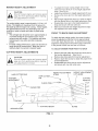
HOW TO USE YOUR
ATTACHING
MOWER
STOPPING
o
o
o
•
Move blade clutch lever to Off position.
Move engine shut off switch to Off position.
Move engine throttle to Stop position.
•
STARTING
•
•
•
®
®
•
MOWER
TO TRACTOR
Place mower behind tractor and back tractor up to it
for attaching. (See Fig. 3)
Slide tow bar of mower over tractor drawbar so that
the hitch pin holes line up.
insert hitch pin until it extends through the bottom of
the tow bar.
Insert hair cotter pin through hitch pin.
Move engine shut off switch to On position.
Move engine throttle to Full position.
Move choke to full.
Move blade c_utch lever to Off position.
Pull start rope.
Move engine choke to Off position after engine
starts.
HITCH PIN
USE
TRACTOR
DRAWBAR
Sit on tractor seat.
,
•
®
Raise blade clutch lever to Engage position.
Operate tractor at medium ground speed.
(3-4 MPH)
HAIR COTTER PIN
Refer to Safety Rules on page 3 and to
the Slope Guide on page 23 regarding
operation of mower on slopes.
FIG. 3
TRANSPORTING
®
Shut off engine.
Place mower deck in the highest position directly
behind tractor.
CAUTION:
Never operate the mower without discharge
chute cover in its proper place.
10
MOWER
HEIGHT
ADJUSTMENT
®
CAUTION:
Shut off mower engine and remove spark
plug wire from spark pHug before making
any adjustments to mower.
®
The cutting height range is approximately 1-t/2 to 4-1/2
inches. The heights are measured form the ground to
the blade tip with the engine not running. These heights
are approximate and may vary depending upon soil
conditions, height of grass and types of grass being
mowed.
o
•
o
FRONT TO BACK
The average lawn should be cut to approximately 2I/2 inches during the cool season and to over 3
inches during hot months. For heaJthier and better
looking tawns, mow often and after moderate
growth.
For best cutting performance, grass over 6 inches in
height should be mowed twice. Make the first cut
relatively high, the second to desired height.
CUTTING
HEIGHT
RAKE ADJUSTMENT
To obtain the best cutting results, the mower housing
should be adjusted so that the front is approximately
1/4" to 3/4" lower than the rear. To check front to back
adjustment measure from the bottom edge of the deck
to the ground at both front and rear of the deck.
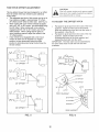
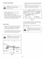
TO ADJUST MOWER FROM FRONT TO BACK
ADJUSTMENTS
,,
Remove two hair cotter pins from two clevis pins in
the tow bar adjustment.
(See Fig. 4)
Remove two clevis pins from tow bar adjustment.
Raise or lower the tow bar to obtain the proper front
to back adjustment.
Reassemble two clevis pins to tow bar adjustment
and secure with two hair cotter pins.
o
e
CAUTmON:
Shut off mower engine and remove spark
plug wire from spark pHug before making
any adjustments to mower.
HEIGHT ADJUSTMENT
STRAP
HAIR COTTER PINS
TOW BAR
ADJUSTMENT
To adjust the mower cutting height remove hair
cotter pin from clevis pin in the height adjustment
strap. (See Fig. 4)
Apply down pressure to height adjustment lift lever.
Remove the clevis pin from the height adjustment
strap.
Move height adjustment strap up or down to align it
with the desired hole in the height adjustment strap.
Reassemble clevis pin to the height adjustment
strap and secure with hair cotter pin.
Make sure that both side height adjustment straps
are adjusted to the same height.
HEIGHT ADJUSTMENT
LIFT LEVER
HAIR COTTER __._.
PIN
__
\\
j!
CLEVIS PINS'
CLEVIS PiNS
/
//
/
i
i
TOW BAR
/
L
CUTTING HEIGHT
GROUND LEVEL
FIG. 4
11
BLADE
HEIGHTS
CUTTING
1-1/2"
2"
2-!/2"
3o
3-1/2 _
4"
4ol/2 _
TOW HITCH OFFSET
ADJUSTMENT
CAUTmON:
Shut off mower engine and remove spark
plug wire from spark plug before making
any adjustments to mower.
This tow behind mower has been designed to mn offset
from the center of the tow vehicle to give additional
cutting width.
o The adjustable tow hitch of this mower can be set Jn
four positions, straight, Appro×imately 15" offset,
29" offset and 39" offset to either side. (See Fig. 5)
® When cutting with a tow vehicle already equipped
with a 42", 46", or 50" mower, we recommend using
the 39" offset. When cutting with a tow vehicle
equipped with 36", 38" or 40" mower, use the 29"
offset position. When cutting heavier grass or
when conditions warrant, adjust the mower to the
15" offset position.
o If tow vehicle is not equipped with a mid mount
mower the hitch can be adjusted to a straight
position, but we recommend using the offset
position to eliminate grass being crushed down by
the tow vehicle.
TO ADJUST
THE OFFSET
HITCH
o
Pull back the pivot latch from the notch of the front
quadrant. Adjust the hitch tube to the desired
offset and release the pivot latch into the notch of
the quadrant. (See Fig. 6)
•
Pull back the pivot latch from the notch of the rear
quadrant. Adjust the hitch tube to the
corresponding notch of the front quadrant and
release the pivot latch into the notch.
IMPORTANT: The hitch tube must be assembled to
the same offset notch in both the front and rear
quadrants.
HT
OFFSET
OFFSET
LATCH
39 _ OFFSET
39"OFFSET
LATCH
FRONT
QUADRANT
29" OFFSET
15
STRAIGHT
REAR QUADRANT
FNG. 5
FIG. 6
12
BEFORE
@
STARTING
ENGINE
MOWING
Fill engine with oil. (See engine manual for proper
procedure and requirements)
Add gasoline. Fill fuel tank using fresh cmean
unleaded gasoline. (See tractor manual for safe
filling procedure and storage instructions)
CAUTION:
Tragic accidents can occur if the
operator is not alert to the presence of
children. Children are often attracted to
the machine and the mowing activity.
NEVER assume that children will remain
where you last saw them.
CAUTION:
Filt to bottom of fuel tank filler neck. Do
not overfill. Wipe off any spilled oil or
fuel. Do not store, spill or use gasoline
near open flame.
TO START
CAUTION:
NEVER carry children. They may fall off
and be seriously injured or interfere with
safe operation.
ENGINE
IMPORTANT: Avoid prolonged mowing of ditches with
slopes greater than 15 degrees. Small engines become
starved for oil at angles greater than 15 degrees and
should only be used for brief periods on such slopes. Be
sure the engine is tilled to the maximum oil level when
mowing on slopes.
CAUTION:
Keep the blade clutch lever in
"Disengaged"
position when starting
engine
Mowing should be started with tractor in low gear
and speed increased only as mowing conditions wil!
safely permit.
Mower will perform at its best when engine throttle is
set for full throttle.
You wil! obtain better mowing results in grassy areas
if they are mowed when the grass is approximately
4" to 5" maximum height. While your mower wil! cut
grass taller than 5", you will notice a substantial
increase in engine power required and some change
in the finished appearance of the area mowed.
Mowing conditions will vary from place to place,
including the types of grass which are being mowed,
such as fine stalk, coarse stalk, and dense or sparse
grasses. When mowing tall grass you may find that
certain grasses may be pressed downward under
the wheels so that they will not mow properly. If
this condition exists you may have to mow the area
twice, the first mowing with the mower raised and the
second mowing at the desired height. If it is practical,
you wil! achieve better results if the second mowing is
at right angle to the previous mowing.
Do not mow grass when it is wet. Wet grass will plug
mower and leave undesirable clumps. Allow grass to
dry before mowing.
Always operate mower engine at full throttle when
mowing to assure better mowing performance and
proper discharge of material. Regulate ground speed
by selecting a gear low enough to give the best
cutting performance and quality of cut.
When operating any attachment, select a ground
speed that will suit the terrain and give the best
performance for the attachment being used.
When mowing slopes, always mow them up and
down at slow speed. Never mow across slopes. Refer
to Slope Operation on page 3 and to the Slope Guide
on page 23.
•
Make sure spark ptug wire is propedy connected.
Place choke control in "CHOKE" position if the
engine is cold. A warm engine may not require
choking to start.
•
Move engine throttle to full position.
o Grasp starter handle with one hand. Pull rope out
slowly until engine reaches start of compression
cycle (rope will pul! stightly harder at this point)
® Pull roper with a rapid, continuous, full arm stroke.
o Keep a firm grip on starter handle and let rope
rewind slowly. Do not let starter handle snap back
against starter.
When engine starts move choke to open position.
•
AHow engine to warm up for a few minutes before
engaging blades.
NOTE: tf at a high altitude (above 3000 feet) or in cold
temperatures (below 32°F), the carburetor fuel mixture
may need to be adjusted for best performance. (See
Service and Adjustments section of the engine manual
BREAKING
mNYOUR
PROCEDURES
MOWER
Break in your belts, pulleys, and engine before you
actualty begin mowing.
Start engine, engage blade control to start blades
rotating and allow blades to rotate for approximately
five minutes to break in mower and engine.
CAUT!ON:
Check area under and around mower for
any objects that could be thrown from
under mower. Make sure that mower
discharge area is clear.
13
GENERAL
RECOMMENDATIONS
Once a year you should replace the spark plug,
c_ean or replace air filter, and check blades and
belts for wear, A new spark plug and clean air filter
assure proper airofuel mixture and help your engine
run better and last longer.
The warranty on this Vehicfe does not cover items that
have been subjected to operator abuse or negligence. To
receive full value from the warranty, operator must
maintain unit as instructed in this manual.
BEFORE
Some adjustments witl need to be made periodicatiy to
propedy maintain your unit.
All adjustments in the Sewice and Adjustments section of
this manual should be checked at least once each season.
o
o
USE
Check engine oil bevel.
Check blade operation
Check for _oose fasteners.
MAINTENANCE
FILL IN DATES
AS YOU COMPLETE
REGULAR SERVICE
SERVICE
DATES
Check Engine Oi_ Leve_
Change Engine Oi!
Inspect Spark Arrester Muffler
Inspect Air Screen
i
Check and Clean Air Cleaner
Replace Air Cleaner Cartridge
Clean Engine Cylinder Fins
Replace Spark Plug
Lubricate Spindles
1
Change more often wt_en operating
2 o Service more often when operating
ENGINE
unaer a heavy load or in high ambient
temperatures
in d_rty or dusty conditions_
MAUNTENANCE
(_)
Refer to engine manual when performing
maintenance on engine.
(_)
REFER TO ENGINE MANUAL
(_
GENERAL PURPOSE GREASE
(_
IMPORTANT: Do not oi! or grease pivot points.
Viscous lubricants will attract dust and dirt that can
cause wear on pivot points. If you feel they must be
lubricated, use only a dry powdered graphite type
lubricant.
ENGINE
WHEEL
14
WHEEL
CLEANmNG THE MOWER
.
.
CAUTION: Disconnect spark plug
wire from spark plug before working on
underside of mower.
•
.
•
When grinding, take care to maintain blade balance.
Check blade for proper balance before reinstalling to
moweE
To check and balance blade use a balancing
machine or, fixture as shown in figure 8. File material
off heavier end of blade until it is balanced.
_CENTER
THE BLADE'S
CENTER
;d, ON NAIL.
DO NOT LET BLADE
_BENCH.
A BALANCED
BLADE
Clean the underside of your mower to remove
buildup of grass clippings.
Clean any gasoline, oil, or foreign matter from
engine, painted surfaces and wheels.
We do not recommend using a garden hose to clean
mower unless the electrical system, muffler, air filter
and carburetor are covered to keep water out. Water
in engine can result in shortening engine life.
_REMAIN
HOLE
TOUCH
WILL
LEVEL,
WORKBENCH
THIN
NAnL
FINISHING
LUBRICATED
WITH
DROP
OF O_L
FIG. 8
To assure satisfactory operation, we recommend that
you discard old blades and replace them with new ones
before the start of each mowing season.
BLADE
CARE
NOTE: Check nuts and blades occasionally to make
sure nuts are tight.
For best results, mower blade must be kept sharp.
The blades can be sharpened with a few strokes
of a file or on a grinding wheel. Do not attempt to
sharpen blades while blades are on mower.
•
CAUTION:
To remove blade for sharpening, use wooden block
to hold blade while removing the blade mounting nut.
The nuts have right hand threads. (See Fig. 7.)
CAUTION: Do not handle mower blades
with bare hands. Careless or improper
handling may result in serious injury.
WOOD BLOCK
Shut off mower engine and
remove spark plug wire from spark plug
before making any adjustments or repairs to
mower.
BLADE
FiG. 7
15
t
1
REPAIR PARTS
CHECKUNG
Your rotary mower has been produced with components
designed for your unit. Although standard \/obelts,
bearings, blades pulleys etc. may look like the parts
used on your rotary mower, many are of a different
construction and could in some cases cause the mower
to malfunction.
,
,
o
Remove \/obelt cover from right side of unit.
Place Blade Control Lever in the "ENGAGED"
position.
Check tension spring length. It should be 5-3/8" to
5o5/8" over the coils of the Spring Body. See Fig. 9.
ADJUSTING
For continued satisfactory performance, use only repair
parts supplied by the manufacturer. See you Sears
Service Center for replacement parts.
BELT REPLACEMENT
o
o
o
,_
•
_,
®
,_
,_
®
,
Move Blade Clutch Lever to the "DISENGAGED"
position.
Remove two bett covers. (See Fig 9)
Loosen three bolts and pivot belt guides away from
pulleys
Move belt brake away from spindle pulleys, and
remove Vobelt from around two spindte pulleys.
Remove V-belt from around engine pulley.
Disconnect small spring from idler arm.
Grasp body of lane idler spring and pull spring to
the right side of mower until idler pulley is against
spindle pulley.
Remove Wbelt from idler pulley.
Place new V-belt onto idBer pulley and release large
spring to allow idler to return to original position.
Reconnect small spdng to idler arm.
Assemble V-belt around engine pulley.
Move belt brake away from spindle pulleys then
assemble V-belt onto spindle pul_eys.
Place Blade Clutch Lever into "ENGAGED" position.
Reposition three belt guides to odginal position with
approximately 1/16" cmearance from pulleys and
retighten botts to secure belt guides.
To Decrease Drive Spring Tension
.
Place blade clutch lever in the "DISENGAGED"
position.
Loosen the outer nut of the dutch cable.
Tighten the inner nut to decrease spring tension.
NOTE: Belt Guides shouid not touch V-belt or pulleys
when unit is in engaged position.
•
Place blade clutch lever in the "DISENGAGED"
position.
Loosen the inner nut of the clutch cable.
Tighten the outer nut to increase spring tension.
NOTE: For every 1/8" adjustment made to the cable
you will get approximately 1/8" movement on the tension
spring.
from
spark plug
before replacing
V-belL
CAUTION:
Disconnect
spark plug
wire
•
e
DRIVE TENSION
To Increase Drive Spring Tension
,,
•
DRIVE TENSION
Reassemble two belt covers and return Blade Clutch
Lever to "DISENGAGED" position.
16
1
LOOSEN
INNER NUT
TIGHTEN
OUTER NUT
IDLER PULLEY
ENGINE PULLEY
SMALL SPRING
BOLT
BELT GUIDE
BELT GUIDE
1
I
I
PULLEY
I
BELT GUIDE
TENSION
(LARGE)
SPRING
I
BELT
BRAKE
SPINDLE
FIG. 9
17
ENGINE OiL
Immediately prepare your mower for storage at the end
of the season or Jf the unit will not be used for 30 days
or more.
Drain oil with engine shut off but still warm. Replace
old oil with new engine oil. (See engine manual.)
MOWER
CYUNDER
When the mower is to be stored for a period of time,
clean it thoroughly, remove all did, grease, leaves, etc.
Store in a clean dry area.
Clean entire mower (See °CLEANING")
Lubricate as shown in the Customer Responsibilities
section of this manual.
Be sure that aH nuts, botts, screws, and pins are
securely fastened. Inspect moving parts for
damage, breakage an wear. RepJace if necessary.
.
Touch up all rusted or chipped paint surfaces; sand
lightly before painfing,
o
®
•
OTHER
®
o
CLEANmNG
CAUTION: Disconnect spark plug
wire from spark plug before working on
underside of mower.
o
o
•
,,
Clean the underside of your mower to remove
buiJd-up of grass and trash,
Keep finished surfaces and wheels free of all
gasoline, oil, etc.
We do not recommend using a garden hose to
clean mower unless the electdcal system, muffler,
air filter, and carburetor are covered to keep water
out. Water in engine can result {n shortening engine
life.
®
Do not store gasoline from one season to another.
Replace your gasoline can if your can starts to rust.
Rust and/or dirt in your gasoline will cause
problems.
If possible, store your unit indoors and cover it to
give protection from dust and dirt.
Cover your unit with a suitable protective cover that
does not retain moisture. Do not use plastic.
PJastic cannot breathe which allows condensation to
form and will cause your unit to rust.
CAUTION: Never cover mower while
engine and exhaust are stil! warm. Cover
may ignite, causing a fire.
CAUTION: Never store a mower with
gasoline in it's tank inside a building where
fumes may reach an open flame or spark.
Allow the engine to cool before storing in
any enclosure.
ENGINE
o
Remove spark plug.
Pour one ounce (29 m0 of oil through spark plug
hole into cylinder.
Pull starter handle s_owly a few times to distribute
oil
Replace with new spark plug.
Never use engine or carburetor cleaner products in
the fuel tank or permanent damage may occur.
Use fresh fuel next season.
NOTE: Fuel stabilizer is an acceptable alternative in
minimizing the formation of fuel gum deposits during
storage, Add stabilizer to gasoline in fuel tank or
storage container. Always follow the mix ratio found on
stabilizer container. Run engine at least 10 minutes
after adding stabilizer to allow the stabilizer to reach the
carburetor. Do not drain the gas tank and carburetor if
using fuel stabilizer.
18
19
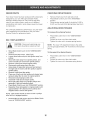
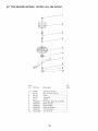
42" TOW BEHIND MOWER o MODEL
NO. 488.243293
\
91
27
/
j-
20
_7
42" TOW BEHIND MOWER o MODEL
NO. 486.243293
item
No.
Qty,
Req.
Item
No.
Mower Deck Pan ..........................................
1
67.
HA23526
Hitch Tube ...................................................
1
Rod- Deflector Mounting ..............................
Pulley (included with item 41) ......................
Washer, 3/8" x 7/8" x .08". ............................
Nut - 5/16-18 Hex Lock ................................
1
2
3
8
68.
69.
70.
71.
48840
HA123!4
HA22996
HA22997
Hitch Assembly ............................................
Mower Blade ................................................
Beltevilte Washer ..........................................
Nut, 9/16-18 Hex ..........................................
Flat Washer ..................................................
1
2
2
2
2
72.
73.
74.
75.
76.
714-0121
HA23638
47081
HA456151
HA23263
Self Tapping Screw ......................................
Danger Decal ..............................................
Left Hand Wheel Mounting Bracket .............
Right Hand Wheel Mounting Bracket ..........
Cotter Pin ....................................................
Clevis Pin ....................................................
Wheet ..........................................................
Flat Washer, 13/16" x 1-1/2" x. 134". ..........
Flat VVasher .................................................
8
1
1
1
8
2
2
2
2
Screw, 3/8-16 x 1-1/4Thread Forming ....... 25
Belt Guide ....................................................
4
77.
78.
HA23229
HA23646
Brake Spring Assembly ................................
Brake Rod ....................................................
Washer, 1/2" x 1-1/4" x .083". ......................
Clutch BelIcrank ...........................................
Nut, 1/2-13 Hex Lock ...................................
Brake Release Rod ......................................
Hair Cotter Pin .............................................
Bolt, 5/16-18 x 2" Hex Head Grade 5 ...........
Idler Tension Spring .....................................
Idler Bracket .................................................
1
1
2
1
6
1
5
3
1
1
79.
80.
81.
82.
83.
84.
85.
86.
87.
88.
44101 *
HA24441
HA20186
HA23760
HA23761
HA23527
HA!5200
43062*
HA19445
43012*
Idler Pulley ...................................................
Flat Washer ..................................................
Bolt, 3/8-16 x 1-3/4" Hex Head ....................
Interlock Bracket ..........................................
Nut, 3/8-16 Hex Lock ...................................
Interlock Switch ............................................
1
8
1
1
4
1
89.
90.
91.
92.
93.
94.
HA23832
HA23586
HA11947
43088
47707
HA181668*
Hub Cap ......................................................
Height Adjustment Strap .............................
Cotter Pin, 3/32" x 3/4". ...............................
Strap, Latch .................................................
Spring, Latch ...............................................
Clip- Hose/Cable 1/2". ................................
Clip - Hose/Cable 3/8". ................................
Lever -Ctutch ..............................................
Washer, 13/32" x 1-3/16" x 3/16". ...............
Bolt, 3/8-16 x 1-1/2" Hex Head ...................
Spring ..........................................................
Bolt, 1/4-20 x 3/4" Hex Head .......................
Wire .............................................................
2
2
1
2
2
3
3
1
2
1
1
2
1
Screw, #10-16 x 1/2" Setf Tapping ............... 6
Bolt, 1/4-20 x 1-!/2" Hex Head .................... 1
Nut, 1/4-20 Hex Lock ...................................
8
95.
96.
97.
HA4143
43601
HA120389
Extension Spring ..........................................
Clutch Cable ................................................
Module Connector ........................................
Module .........................................................
Screw, #10-24 x 1/2" Pan Head ...................
Washer, #10 Med. Lock ................................
Nut, #10-24 Hex ...........................................
Engine Mounting Plate .................................
10.5 HP Engine ............................................
Spindle Assembly (see page 22) ................
Pulley ...........................................................
Set Screw, 5/16-18 x 5/16" Socket Hd .........
Square Key ..................................................
Danger Decal ...............................................
Danger Decal ...............................................
V-BeR ............................................................
Bolt, 3/8-16 x 1" Hex Head ...........................
Rubber Grommet .........................................
Clevis Pin .....................................................
1
1
1
1
2
2
2
1
1
2
1
2
1
2
2
1
1
1
2
98.
99.
100.
101.
102.
103.
104.
105.
NP
HA23732
HA23733
48837
HA23792
25051
25052
48795
43182
48839
Operator's Presence Seat ...........................
Cord Clip .....................................................
Washer, 1/4" Std .........................................
Grip - Handle ...............................................
Bolt, 7/16-20 x 1-1/4" Hex Head .................
Washer, 1" x 13/16" Thick ...........................
Washer, 1.59" x 1.032" x .06". .....................
Washer, 1/2" x 1-1/4" x .083". .....................
Tank, Gasoline ............................................
Cap, Gasoline Tank .....................................
Fuel Line .....................................................
Clamp, Fuet Line .........................................
Cover, Gas Tank ..........................................
Bracket, Tank Mounting ...............................
Screw, 1/4"x 1-1/4" Self Tapping ................
Bolt, Hex 5/!6-18 x 3/4". .............................
Owner's Manual
1
2
4
2
1
2
1
3
1
1
1
2
1
2
4
4
Towbar Assembly .........................................
Hitch Pin .......................................................
Hair Cotter Pin .............................................
On/Off Switch ...............................................
Decal - Engine Shut Off ...............................
Clutch Lever Decal .......................................
Wire Harness ...............................................
Deflector .......................................................
1
1
1
1
1
1
1
1
Decal - Operation .........................................
Mower Roller ................................................
Bolt, 1/2-13 x 7" Hex Head ..........................
1
1
1
Nut, Special (included with item 41) .............
Bolt, 3/8-16 x 2-1/2" Hex Head ....................
Deflector Spring ...........................................
Sears Logo Decal ........................................
Belt Cover ....................................................
2
4
1
1
2
1.
2.
3.
4.
5.
6.
7.
8.
9.
10.
11.
12.
13.
14.
15.
16.
17.
18.
19.
20.
21.
22.
23.
24.
25.
26.
27.
28.
29.
30.
31.
32.
33.
34.
35.
36.
37.
38.
39.
40.
41
42.
43.
44.
45.
46.
47.
48.
49.
50.
51.
52.
53.
54.
55.
56.
57.
58.
59.
60.
61.
62.
63.
64.
65.
66.
Part No,
HA23834
HA23598
49112
43081*
43064*
HA23519
HA23516
HA23246
HA124634"
HA20129
HA23193
HA22981
HA64064
HA22987
HA!20389
HA23518
43262*
HA22948
47134
44180
HA23196
HA23258
HA15015
HA6979
41576*
HA23197
43082*
HA17322
HA9411666"
43648*
43013*
HA3293
HA24617
HA23253
HA23252
45040*
736-0722*
712-0121"
HA23513
2157020115-E1
64675
HA22994
HA!15321"
HA3073
HA17285
HA12315
HA22980
43001*
HA19484
HA23636
HA23644
HA20988
714-0117
45084
HA23262
HA23647
HA23612
HA23597
HA23755
HA12138
HA126145"
49110
43432*
HA12988
44059
HA23645
Deacription
Part No,
Description
*Standard Hardware - Purchased Locally
21
Qty.
Req.
42" TOW BEHIND MOWER o MODEL
NO. 488.243293
item
No.
Part No.
1-6
1.
2.
3.
4.
5.
6.
7.
8.
9.
10.
64675
49110
49112
49109
49111
HA23242
HA23245
HA23516
HA23246
HA20129
HA 124634
Description
Qty.
Req.
SIGHT AND HOLD THIS LEVEL WITH A VERTICAL TREE
A POWER POLE
b_
I
_
A CORNER OF A BUILDING
OR A FENCE POST
O
@
Weo
o
4_
CAUTION: DO NOT OPERATE YOUR TRACTOR AND TOW BEHIND
MOWER ON A SLOPE IN EXCESS OF 10 DEGREES. BE SURE OF
YOUR TRACTOR'S TOWING AND BRAKING CAPABILITIES BEFORE
OPERATING ON A SLOPE. AVOID ANY SUDDEN TURNS OR
MANEUVERS WHILE ON A SLOPE.
For repair of major brand appliances
iiiiiiiiiiiiiiiiii
it1 your own home...
no matter who made it, no matter who soMdit!
iiiiiiiiiiiiiiiiii
1-800-4-MY-H OM EsMAnytime,
iiiiiiiiiiiiiiiiiiiiiiiiiiiiiiiiiii
day or night
(1-800-469-4663)
iiiiiiiiiiiiiiiiiiiiiiiiiiiiiiiiiii
wwwosearsocom
iiiiiiiiiiiiiiiiiiiiiiiiiiiiii
iiiiiiiiiiiiiiiiiiiiiiiiiiiiiiiiiii
To bring in products such asvacuums, lawn equipmentand
electronics
iiiiiiiiiiiiiiiiiiiiiiiii
iiiiiiiiiiiiiiiiii
for repair, call for the location of your nearest Sears Parts & Repair Center. iiiiiiiiiiiiiiiiiiiiiiiii
iiiiiiiiiiiiiiiiii
::::::::::::::::::::::::::::::
_:_
1-800-488-1222
iiiiiiiiii:ii!iiiiiiiiiii
Anytime,
iiiiiiiiiiiiiiiiii
iiiiiiiiiiiiiiiiii
day or night
iiiiiiiiiiiiiiiiii
iiiiiiiiiiiiii:!iiiil
iiiiiiiiiiiiiiiiii
iiiiiiiiiiiiiii;,ii
WWW,_;ea['_;,COR3
iiiiiiiiiiiiiiiiii
1 - 800 - 388 - PART Gam = 11p..m CST,
(1-8oo-36_-z2zs)7days
aweek
www.sears.com/partsdirect
Topurchase
orinquire
about
aSears
Service
A_reement:
Para pedir servicio de reparaci6n a domicilio,
y para ordenar piezas con entrega a domicilio:
1-888-SUoHOGAR
Au Canada
pour service
s_
(1=877=533=6937)
(1-888-784-6427)
® Registered Trademark
© Sears
Roebuck
and Co
en fran£ais:
s_
1-877-LE-FOYER
/ TM Trademark
of Sears, Roebuck and CO.
® Marca Registrada / 7_ Marca de Fabrica de Sears
Roebuck
and Co