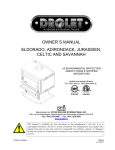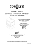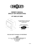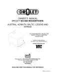
1
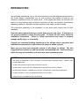
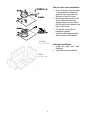
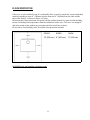
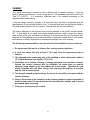
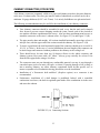
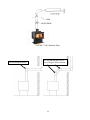
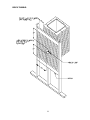
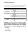
INSTRUCTIONS & OPERATIONS MANUAL
WHISTLER EPA EXEMPT
US ENVIRONMENTAL PROTECTION
AGENCY 28A CERTIFIED
WOODSTOVES
Verified and tested following
UL 1482 Standards by:
Manufactured by : STOVE BUILDER INTERNATIONAL INC.
1700, Léon-Harmel, Québec (Québec) G1N 4R9
45424
TABLE OF CONTENTS
INTRODUCTION ................................................................................................................. 3 INSTALLATION ................................................................................................................... 5 POSITIONING THE STOVE ......................................................................................................... 5 CLEARANCES FROM COMBUSTIBLES ................................................................................... 6 REDUCED CLEARANCES ........................................................................................................... 6 FLOOR PROTECTOR .................................................................................................................. 11 CHIMNEY..................................................................................................................................... 12 CHIMNEY CONNECTOR (STOVE PIPE) ................................................................................. 13 TYPICAL INSTALLATIONS ...................................................................................................... 15 WOODSTOVE UTILISATION............................................................................................ 19 AVERAGE ENERGY YIELD OF ONE AIR DRIED CORD OF CUT WOOD ......................... 19 TESTING YOUR WOOD ............................................................................................................. 20 THE FIRST FIRES........................................................................................................................ 20 IGNITION ..................................................................................................................................... 20 ASH DISPOSAL ........................................................................................................................... 21 AIR CIRCULATION SYSTEM ........................................................................................... 22 MAINTENANCE ................................................................................................................ 22 GLASS........................................................................................................................................... 22 GASKETING ................................................................................................................................ 22 PAINT ........................................................................................................................................... 23 FREQUENTLY ASKED QUESTIONS ............................................................................... 24 WHAT DO THE WORDS “DRAFT” AND “NEGATIVE PRESSURE” MEAN? ..................... 24 CAN I MODIFY MY STOVE TO INSTALL A GLASS DOOR? ............................................... 31 WHEN DO I NEED TO REPLACE THE FIREBRICKS? ........................................................... 31 ORDERING REPLACEMENT PARTS ....................................................................................... 31 CENTURY HEATING LIMITED WARRANTY .................................................................... 32 2
INTRODUCTION
Stove Builder International, one of the most important stove and fireplace manufacturer in
the Unites States, congratulates you on your purchase and wishes to help you get
maximum satisfaction from your wood stove. In the pages that follow, we will give you
advice on wood heating and controlled combustion as well as technical specifications
regarding installation, operation and maintenance of the model you have chosen.
The instructions pertaining to the installation of your wood stove comply with UL-1482
standards.
Read this entire manual before you install and use your new stove. If this stove is
not properly installed, a house fire may result. To reduce the risk of fire, follow the
installation instructions. Failure to follow instructions may result in property
damage, bodily injury, or even death.
Consult your municipal building department or fire officials about restrictions and
installations requirements in your area and the need to obtain a permit.
Make sure you keep this instruction manual. It will always be helpful. We also
suggest that you consult our web site at www.centuryheating.com. It will provide you
with a full range of information, such as how to order replacement parts.
CAUTIONS:
• HOT WHILE
IN OPERATION. KEEP CHILDREN, CLOTHING AND FURNITURE AWAY. CONTACT MAY
CAUSE SKIN BURNS.
•
DO NOT USE CHEMICALS OR FLUIDS TO IGNITE THE FIRE.
•
DO NOT LEAVE THE STOVE UNATTENDED WHEN THE DOOR IS SLIGHTLY OPENED.
•
DO NOT BURN WASTES, FLAMMABLE FLUID SUCH AS GASOLINE, NAPHTHA OR MOTOR OIL.
•
DO NOT CONNECT TO ANY AIR DISTRIBUTION DUCT OR SYSTEM.
•
ALWAYS CLOSE THE DOOR AFTER THE IGNITION.
3
Cast iron flue collar installation:
1. Peel off the tape from the back
of the gasket and attach the
gasket to the rope groove at
the back of the flue collar;
2. Mount flue collar on top of the
stove. Make sure that the
damper holes on each side of
the flue collar are parallel to the
back of the stove;
3. Fix the flue collar with the
hardware supplied;
4. Install the flue damper inside
the flue collar as illustrated.
17 bricks
4½’’ x 9’’ x 1¼’’
2 bricks
4½’’ x 4½’’ x 1¼’’
4
Firebricks installation:
1. Install the back and side
firebricks.
2. Install the bottom firebricks
INSTALLATION
SAFETY NOTICE
• IF THIS STOVE IS NOT PROPERLY INSTALLED, A HOUSE FIRE MAY RESULT. TO REDUCE THE RISK
OF FIRE, FOLLOW THE INSTALLATION INSTRUCTIONS. FAILURE TO FOLLOW INSTRUCTIONS MAY
RESULT IN PROPERTY DAMAGE, BODILY INJURY, OR EVEN DEATH.
• CONSULT YOUR MUNICIPAL BUILDING DEPARTMENT OR FIRE OFFICIALS ABOUT RESTRICTIONS
AND INSTALLATIONS REQUIREMENTS IN YOUR AREA.
• USE SMOKE DETECTORS IN THE ROOM WHERE YOUR STOVE IS INSTALLED.
• KEEP FURNITURE AND DRAPES WELL AWAY FROM THE STOVE.
• NEVER USE GASOLINE, GASOLINE-TYPE LANTERN FUEL, KEROSENE, CHARCOAL LIGHTER FLUID,
OR SIMILAR LIQUIDS TO START OR "FRESHEN UP" A FIRE. KEEP ALL SUCH LIQUIDS WELL AWAY
FROM THE STOVE.
• IN THE EVENT OF A CHIMNEY FIRE, CALL THE FIRE DEPARTMENT.
• DO NOT CONNECT TO ANY AIR DISTRIBUTION DUCT OR SYSTEM.
• A SOURCE OF FRESH AIR INTO THE ROOM OR SPACE HEATED SHALL BE PROVIDED WHEN
REQUIRED.
POSITIONING THE STOVE
It is very important to position the wood stove in an area that will favour the most efficient heat
distribution throughout the house. The stove should therefore be installed in the room where the
most time is spent, and in the most spacious room possible. Recall that wood stoves produce
radiating heat, the heat we feel when we are close to a wood stove. A wood stove also functions by
convection, that is through the displacement of hot air accelerated upwards and its replacement with
cooler air at the floor level. The stove’s convection effect is facilitated by the installation of a
blower.
5
CLEARANCES FROM COMBUSTIBLES
Clearances to any combustibles when measured directly from the floor protector to the
ceiling must be a minimum of 84" (2134 mm). Clearances to any combustibles when
measured directly from the front of the stove must be a minimum of 48" (1219 mm). The
stove must also be placed so as to maintain the minimum clearances to combustible walls
specified for each type of connector used. It is of outmost importance that the clearances
to combustible materials be scrupulously respected upon installation of the stove you have
selected. Refer to the tables below :
A- REAR
24”
B- SIDE C - CORNER
26”
26”
You may decrease these clearances by installing heat radiation shields between the walls
or the ceiling and the stove. These heat radiation shields must be installed permanently,
and can include sheet metal, a rigid non-combustible sheet or a masonry wall. The
installation standards of such heat radiation shields are listed on the following page.
IT IS STRICTLY FORBIDDEN TO PLACE WOOD WITHIN MINIMUM CLEARANCES
REDUCED CLEARANCES
You may decrease the clearances by installing heat radiation shields between the walls or
the ceiling and the stove. These heat radiation shields must be installed permanently, and
can include sheet metal, a rigid non-combustible sheet or a masonry wall.
Clearances of not less than 1" (25 mm) and not more than 3" (76 mm) between the bottom
of the shield and the floor and not less than 3" (76 mm) between the top of the shield and
the ceiling must be respected to allow vertical air circulation behind the shield. The shield
must extend 20" (500 mm) above the stove top and 18" (450mm) to each side of the stove
(see Graphic 1).
6
Following the installation of such a heat radiation shield, the clearances mentioned on the
stove certification plate may be reduced as stated in the following table.
Reducing Clearances With
Shielding
TYPE OF PROTECTION
Sides and
Rear/Back
Top
Sheet metal, a minimum of 0,024" (0,61mm) spaced
out at least 1" (25mm) by non-combustible spacers
(see graphic 2).
67%
50%
Ceramic tiles, or an equivalent non-combustible
material on fire-proof supports spaced out at least 1"
(25 mm) by non-combustible spacers (see graphic 3).
50%
33%
Ceramic tiles, or an equivalent non-combustible
material on fire-proof supports with a minimum of
0,024" (0,61 mm) sheet metal backing spaced out at
least 1" (25 mm) by non-combustible spacers (see
graphic 4)
67%
50%
Brick spaced out at least 1" (25 mm) by noncombustible spacers (see graphic 5)
50%
N/A
67%
N/A
Brick with a minimum of 0,024" (0,61 mm) sheet metal
backing spaced out at least 1" (25 mm) by noncombustible spacers (see graphic 6).
7
Graphic 1
A- Clearance to combustible material with no protection.
B- 500 mm (20 po.) minimum;
C- 25 mm (1 po.) minimum;
D- Between 25 mm (1 po.) and 75 mm (3 po.) ;
E- 75 mm (3 po.) minimum;
F- 450 mm (18 po.) minimum.
1- Wall shielding ;
2- Non-combustible spacers ;
3- Ceiling shielding ;
4- Combustible wall ;
5- Ceiling;
6- Heater (side view) ;
7- Heater (top view).
8
Graphic 2
A- 25 mm (1 po.) minimum;
1- Combustible wall ;
2- Non-combustible spacer;
3- 0.61 mm (0.024") sheet metal.
Graphic 3
A- 25 mm (1 po.) minimum;
1- Combustible wall;
2- Non-combustible spacer;
3- Fire-proof support;
4- Ceramic tile or equivalent non-combustible material.
_____________________________________________________________________________
Graphic 4
A- 25 mm (1 po.) minimum;
1- Combustible wall;
2- Non-combustible spacer;
3- 0.61 mm (0.024") sheet metal;
4- Fire-proof support;
5- Ceramic tile or equivalent non-combustible material.
9
Graphic 5
A- 25 mm (1 po.) minimum;
1- Combustible wall;
2- Non-combustible spacer;
3- Brick.
Graphic 6
A- 25 mm (1 po.) minimum;
1- Combustible wall;
2- Non-combustible spacer;
3- 0.61 mm (0.024") sheet metal;
4- Brick.
10
FLOOR PROTECTOR
If the stove is to be installed on top of a combustible floor, it must be guarded by a non-combustible
material extending at least 18” (300mm) from the front and 8” (200mm) from the sides and the
back of the firebox., as shown in Figure 1.4 below.
Please note that a floor protection is required with the pedestal models for spark and ash shielding,
but not for limiting floor temperatures from the radiant heat of the stove. The stove was designed
and safety tested so that without any protection, the floor would not overheat.
Please refer to local building codes for suitable floor protection materials.
FRONT
SIDES
BACK
18” (300 mm)
8” (200 mm)
8” (200 mm)
WARNING: do not install in a sleeping room.
11
CHIMNEY
Your wood stove may be hooked up with a factory built or masonry chimney. If you are
using a factory built chimney, it must comply with UL 103 standards; therefore it must be a
Type HT (2100°F). It is extremely important that it be installed according to the
manufacturer's specifications.
If you are using a masonry chimney, it is important that it be built in compliance with the
specifications of the National Building Code. It must be lined with fire clay bricks, metal or
clay tiles sealed together with fire cement. (Round flues are the most efficient).
The interior diameter of the chimney flues must be identical to the stove's smoke exhaust.
(6”). A flue which is too small may cause draught problems, while a large flue favours
rapid cooling of the gas, and hence the build-up of creosote and the risk of chimney fires.
Note that it is the chimney and not the stove which creates the draught effect; your stove's
performance is directly dependent on an adequate draught from your chimney.
The following recommendations may be useful for the installation of your chimney:
1. Do not connect this unit to a chimney flue serving another appliance.
2. It must rise above the roof at least 3' (0.9 mm) from the uppermost point of
contact.
3. The chimney must exceed any part of the building or other obstruction within a
10' (3.04 m) distance by a height of 2' (0.6 m).
4. Installation of an interior chimney is always preferable to an exterior chimney.
Indeed, the interior chimney will, by definition, be hotter than an exterior
chimney, being heated up by the ambient air in the house. Therefore the gas
which circulates will cool more slowly, thus reducing the build-up of creosote
and the risk of chimney fires.
5. The draught caused by the tendency for hot air to rise will be increased with an
interior chimney.
6. Using a fire screen at the extremity of the chimney requires regular inspection in
order to insure that it is not obstructed thus blocking the draught, and it should
be cleaned when necessary.
7. Clean your chimney every 2 months.
12
CHIMNEY CONNECTOR (STOVE PIPE)
Your chimney connector (commonly called stove pipe) and chimney must have the same diameter
as the stove’s exhaust outlet. The stove pipe must be made of aluminized or cold roll steel with a
minimum 24-gauge thickness (0.021" or 0.53 mm). It is strictly forbidden to use galvanized steel.
The following recommendations may be useful for the installation of your chimney connector:
•
Your chimney connector should be assembled in such a way that the male end (crimped)
faces down to prevent creosote dripping outside the joints. Attach each of the sections to
one another with three equidistant metal screws. Also use three equidistant metal screws to
attach the connector to the stove’s exhaust collar. See Figure 2.3 (A) and Figure 2.3 (B).
•
The pipe must be short and straight. All sections installed horizontally must slope at least ¼
inch per foot, with the upper end of the section toward the chimney. See Figure 2.3 (B).
•
To insure a good draft, the total horizontal length of the connector should never exceed 8' to
10' (2.4 to 3.04 m). In the case of vertical installation, the total length of the connector can
be much longer and connected without problem to the chimney at the ceiling level.
•
There should never be more than two 90 degrees elbows in the whole connector and
chimney system. Never start with a 90o elbow. Always go up vertically for at least 2 feet
from the flue spigot before using a 90o elbow.
•
The connector must not pass through any combustible material, nor may it pass through a
concealed space (such as an attic, roof space, or closet). If passing through a wall, ceiling, or
into a masonry chimney, use either chimney components listed for that specific use, or
means acceptable to local authorities having jurisdiction over the installation.
•
Installation of a "barometric draft stabiliser" (fireplace register) on a connector is not
recommended.
•
Furthermore, installation of a draft damper is prohibited. Indeed, with a controlled
combustion wood stove, the draft is regulated upon intake of the combustion air in the stove
and not at the exhaust.
FIGURE 2.3 (A) Connecting Sections
13
FIGURE 2.3 (B) Minimum Slope
Avoid 90 degree eblows
We recommend that you use
two 45 degree elbows instead
14
TYPICAL INSTALLATIONS
FACTORY BUILT CHIMNEY:
RAIN CAP
ROOF FLASHING
18" CLEARANCE
RADIATION SHIELD
WALL RADIATION SHIELD
WALL SUPPORT
CEILING SUPPORT
Wall installation
Vertical installation
15
MASONRY CHIMNEY:
C lay liner
Thimb le
C lean out
door
16
FACTORY BUILT THIMBLE:
17
BRICK THIMBLE:
18
WOODSTOVE UTILISATION
Your heating unit was designed to burn wood only; no other materials should be burnt.
Wastes and other flammable materials should not be burnt in your wood stove. Any type
of wood may be used in your stove, but specific varieties have better energy yields than
others. Please consult the following table in order to make the best possible choice.
AVERAGE ENERGY YIELD OF ONE AIR DRIED CORD OF CUT WOOD
Wood species
High energy yield
Medium energy yield
Low energy yield
Oak
Sugar Maple
Beech
Yellow birch
Ash
Elm
Larch (Tamarack)
Red Maple
Douglas red fir
Silver birch
Alder
Poplar
Hemlock
Spruce
Pine
Bass
Fir
Energy yield
(millions of BTU/cord)
29
28
26
25
24
23
23
23
23
22
18
17
17
17
17
16
13
Data provided by Energy, Mines and Resources - Canada
IT IS EXTREMELY IMPORTANT THAT YOU USE DRY WOOD ONLY IN YOUR WOOD
STOVE. The wood must have dried for 9 to 15 months, such that the humidity content (in
weight) is reduced below 20% of the weight of the log. It is very important to keep in mind
that even if the wood has been cut since one, two or even more years, it is not necessarily
dry, if it has been stored in poor conditions; under extreme conditions, it may even rot
instead of drying. The vast majority of the problems related to the operation of a wood
stove are caused by the fact that the wood used was too damp or had dried in poor
conditions. These problems can be:
• ignition problems
• creosote build-up causing chimney fires
• low energy yield
• blackened windows
• incomplete log combustion
19
Smaller pieces of wood will dry faster. All logs exceeding 6" in diameter should be split.
The wood should not be stored directly on the ground. Air should circulate through the
cord. A 24" to 48" air space should be left between each row of logs, which should be
placed in the sunniest location possible. The upper layer of wood should be protected
from the element but not the sides.
TESTING YOUR WOOD
When the stove is thoroughly warmed, place one piece of split wood (about five inches in
diameter) parallel to the door on the bed of red embers.
Close the door. If ignition of the piece is accomplished within 90 seconds from the time if
was placed in the stove, your wood is correctly dried. If ignition takes longer, your wood is
damp.
If your wood hisses and water or vapour escapes at the ends of the piece, your wood is
soaked or freshly cut. Do not use this wood in your stove. Large amounts of creosote
could be deposited in your chimney, creating potential conditions for a chimney fire.
THE FIRST FIRES
The fresh paint on your stove needs to be cured to preserve it's quality. Once the fuel
charge is properly ignited, only burn small fires in your stove for the first four hours of
operation.
Make sure that there’s enough air circulation while curing the stove. The odours could be
smelled during the 3 or 4 first fires. Never start your stove outside. You will not be able to
see if you are over heating.
IGNITION
Place several rumpled sheets of paper in the centre of the combustion chamber. Place 8
to 10 pieces of small dry kindling wood over the paper in the form of a tent. You may also
place a few pieces of heating wood, but choose the smaller ones. No chemical product
should be used to light the fire.
Before igniting the paper and kindling wood, it is recommended that you warm up the
chimney. This is done in order to avoid back draft problems often due to negative
pressure in the house. If such is the case, open a window slightly near the stove and twist
together a few sheets of newspaper into a torch. Light up this paper torch and hold it as
close as possible to the mouth of the pipe inside the combustion chamber to warm up the
chimney. Once the updraft movement is initiated, you are ready to ignite the stove by
lighting the paper and kindling wood inside the combustion chamber.
We therefore advise you to leave the door slightly opened (1/4") for a 10 to 30 minutes
period, under supervision, in order to allow for good combustion. After this time, you
must close the door.
20
ASH DISPOSAL
Ashes should be removed from the stove every few days or when ashes get to 2 to 3
inches deep. Always empty the stove when it is cold, such as in the morning.
Always dispose of ashes in a metal container with a tight fitting lid. Place this container on
a non combustible floor or on the ground, well away from all combustible materials,
pending final disposal. If the ashes are disposed of by burial in soil or otherwise locally
dispersed, they should be retained in the close container until all cinders have thoroughly
cooled.
CAUTIONS:
• ASHES COULD CONTAIN HOT EMBERS EVEN AFTER TWO DAYS WITHOUT OPERATING THE STOVE.
• THE ASH PAN CAN BECOME VERY HOT. WEAR GLOVES TO PREVENT INJURY.
• NEVER BURN THE STOVE WITH THE ASH TRAP OPEN. THIS WOULD RESULT IN OVER FIRING THE
STOVE. DAMAGE TO THE STOVE AND EVEN HOUSE FIRE MAY RESULT.
• THE INSTALLATION OF A LOG CRADLE IS NOT RECOMMENDED IN YOUR NORTHERN TOOL +
EQUIPMENT WOOD STOVE.
• NEVER PUT WOOD ABOVE THE FIREBRICK LINING OF THE FIREBOX.
21
AIR CIRCULATION SYSTEM
In order to improve air circulation in the room where the wood stove is installed, certain
options are available for specific stove models.
Blower:
A variable speed-control blower is available.
Thermodisc:
The thermodisc is installed on the blower's electrical supply cord, and
it will start the blower when the stove’s temperature reaches 120° F
(49°C) and cut off power when the stove cools down below 100° F
(37°C).
Information regarding installation of the thermodisc is
included with the device.
MAINTENANCE
It is important to perform a visual inspection of the stove every time it is emptied, in order
to insure that no parts have been damaged, in which case repairs must be performed
immediately.
GLASS
•
Inspect the glass regularly in order to detect any cracks. If you spot one, turn the stove
off immediately. Do not abuse the glass door by striking or slamming shut. Do not use
the stove if the glass is broken.
•
If the glass on your stove breaks, replace only with glazing supplied from the dealer.
•
To replace the glass, remove the screws retaining the glass mouldings inside the door.
Remove the mouldings and replace the damaged piece with a new one. Perform the
procedure backwards after replacing. When replacing the glass, you should change
the glass gasket to make sure you keep it sealed.
•
Never wash the glass with a product that may scratch. Use a specialized product,
available in the stores where wood stoves are sold.
•
The glass should be washed only when cold.
GASKETING
It is recommended that you change the door gasket (which makes your stove door air
tight) once a year, in order to insure good control over the combustion, maximum
efficiency and security. To change the door gasket, simply remove the damaged one.
Carefully clean the available gasket groove, apply a high temperature silicone sold for this
purpose, and install the new gasket. You may light up your stove again approximately 24
hours after having completed this operation.
WARNING:
• NEVER
OPERATE THE STOVE WITHOUT A GASKET OR WITH A BROKEN ONE.
STOVE OR EVEN HOUSE FIRE MAY RESULT
22
DAMAGE
TO THE
PAINT
Only clean your stove with a dry soft clothe that will not harm the paint finish.
If the paint becomes scratched or damaged, it is possible to give your wood stove a brand
new look, by repainting it with a 1200o F heat resistant paint. For this purpose, simply
scrub the surface to be repainted with fine sand paper, clean it properly, and apply thin
coats (2) of paint successively. Refer to page 20 of the present manual for the paint
curing process.
23
FREQUENTLY ASKED QUESTIONS
WHAT DO THE WORDS “DRAFT” AND “NEGATIVE PRESSURE” MEAN?
The word “draft” refers to the hot air movement that circulates in your stove’s exhaust
system, moving from the stove to the outside of the house, and carrying with it the
combustion residues. The draft is a natural phenomenon. Hot air weights less than cold
air, causing it to rise. This is why the higher the temperature in the exhaust system, the
stronger the draft. It is also important to say that the “tunnel effect” created by the exhaust
system contributes to increasing the draft effect. This is why chimneys that are
excessively long often create excessive draft, while chimneys that are abnormally short will
have an excessively low draft. The following are often symptoms of a draft problem:
-
Excessively dirty (blackened) glass;
A fire that has a tendency to die quickly when the stove door is closed;
A stove that does not heat enough.
“Negative pressure” can be seen as a “reverse draft”. That is, air will circulate from the
chimney toward the interior of the house. Negative pressure is often what causes
smoking problems. In general, negative pressure is the result of either one or a
combination of the three factors explained below:
1- A cold chimney. Cold air, which is heavier than hot air, has a tendency to go down
the chimney and create the effect of a “clog”. This explains why a stove that has
not worked for a long time and which chimney is very cold will sometimes be hard to
light and cause smoking problems.
2- Negative pressure can also be caused by a “vacuum effect” in the room or the
house. The air in a house is constantly moving. Hot air rises, cold air moves down.
Air can also be mechanically expulsed outside of the house with the use of airmoving devices, such as a range hood, a air exchanger, a dryer, a bathroom fan,
etc. Furthermore, air goes in and out of the house through cracks, doors, windows,
etc. If air leaves a room without being replaced, a “vacuum effect” is created.
Therefore, if a house is well insulated and all windows are closed, the room will
source its air through the easiest alternative route, which is often your stove’s
exhaust system. This creates a negative pressure in your exhaust system. You
now understand why it is often suggested that a window be slightly open in the
room where the stove is located. This enables the room to easily source its air from
outside the house without searching for an alternative route. The vacuum effect
can amplified when your stove is located in the basement. This is due to the fact
that your house itself acts like a chimney. Since hot air will rise to upper floors, it
will “draw” air from the basement of the house. This phenomenon is called the
“chimney stack effect”.
24
3- Wind can also be a third cause of negative pressure. When your house is located
near a structure which height is superior to your roof’s, wind currents can create an
interference with your chimney, leading to negative pressure problems.
Drawings #1 to #5 starting on page 18 will help you understand the explanations
provided in this section.
25
DRAWING #1
DRAWING #1 shows a stove functioning under normal and adequate conditions. Heat rises to the
upper floors and the room where the stove is located has an adequate supply of oxygen. The
chimney draft is sufficient and the combustion gases are evacuated normally through the exhaust
system.
26
DRAWING #2
DRAWING #2 shows the effect of a cold chimney. Cold air creates a reverse draft (negative
pressure), which causes smoking problems. This phenomenon is amplified by the fact that heat
rises, which creates a draft from the basement of the house to the upper floors (“chimney stack
effect”).
27
DRAWING #3
DRAWING #3 shows the effect of negative pressure caused by an air-moving device inside the
house. In the example above, the range hood draws air from inside the house, which is replaced by
air coming from the chimney. The result is a smoking problem.
28
DRAWING #4
DRAWING #4 shows the negative pressure effect caused by wind, influenced by nearby structures
such as a building.
29
DRAWING #5
DRAWING #5 shows the negative pressure effect that can be caused by wind, influenced by nearby
structures such as a tree.
30
CAN I MODIFY MY STOVE TO INSTALL A GLASS DOOR?
It is forbidden to modify a stove. Stoves are safety tested with a specific configuration,
drawings of which are filed with the regulating authorities. Changing the type of door could
lead to serious difficulties with your insurance company in case of fire. It would also
automatically nullify your warranty.
WHEN DO I NEED TO REPLACE THE FIREBRICKS?
The firebricks in your stove are there to protect the steel from the excessive heat of the
flames and embers. Without firebricks, your stove would wear out prematurely. It could also
become to hot and cause objects or structures nearby to catch fire. If you notice that some
firebricks are disintegrated and the steel is directly in contact with the fire or embers, replace
the firebricks immediately. If you only notice cracks on some firebricks, it is not necessary to
replace them. The frequency at which you will change your firebricks depends on how often
you use your stove.
There are different sizes of firebricks. Most stores will sell firebricks with a dimension of
4,5”X9”X1,25”. These firebricks are adequate for many stoves, but will not fit on all Northern
Tool + Equipment units. It is preferable that you visit our parts section in order to clearly
identify the type of firebrick that you need.
ORDERING REPLACEMENT PARTS
Contact your dealer. You can also obtain replacement parts through Inventex at 1-800363-0566. Please make sure you have your stove model number handy.
31
CENTURY HEATING LIMITED WARRANTY
The warranty of the manufacturer extends only to the original consumer purchaser and is not transferable. This warranty
covers brand new products only, which have not been altered, modified nor repaired since shipment from factory. Proof
of purchase (dated bill of sale), model name and serial number must be supplied when making any warranty claim to your
CENTURY dealer.
This warranty applies to normal residential use only. Damages caused by misuse, abuse, improper installation,
lack of maintenance, over firing, negligence, accident during transportation, power failures, downdrafts, or
venting problems are not covered by this warranty.
This warranty does not cover any scratch, corrosion, warping, or discoloration caused by over firing, abrasives or
chemical cleaners. Any defect or damage caused by the use of unauthorized parts or others than original parts void this
warranty. An authorized qualified technician must perform the installation in accordance with the instructions supplied
with this product and all local and national building codes. Any service call related to an improper installation is not
covered by this warranty.
The manufacturer may require that defective products be returned or that digital pictures be provided to support the claim.
Returned products are to be shipped prepaid to the manufacturer for investigation. If a product is found to be defective,
the manufacturer will repair or replace such defect. Transportation fees to ship the product back to the purchaser will be
paid by the manufacturer. Repair work covered by the warranty, executed at the purchaser’s domicile by an authorized
qualified technician requires the prior approval of the manufacturer. Labour cost and repair work to the account of the
manufacturer are based on predetermined rate schedule and must not exceed the wholesale price of the replacement part.
All parts and labour costs covered by this warranty are limited according to the table below.
The manufacturer at its discretion may decide to repair or replace any part or unit after inspection and investigation of the
defect. The manufacturer may, at its discretion, fully discharge all obligations with respect to this warranty by refunding
the wholesale price of any warranted but defective parts. The manufacturer shall in no event be responsible for any
special, indirect, consequential damages of any nature, which are in excess of the original purchase price of the product.
This warranty applies to products purchased after March 1st , 2009.
DESCRIPTION
Combustion chamber (welds only) and castings.
Stainless steel firebox components, secondary air tubes*, surrounds and heat
shields, ash drawer, steel legs, pedestal, trims (aluminum extrusions),
plating* (defective manufacture), and convector air-mate.
Carbon steel firebox components, glass retainers, handle assembly, C-Cast
baffle*, and vermiculite baffle*.
Standard blowers, heat sensors, switches, rheostat, wiring, and other
controls.
Optional blowers, ceramic glass (thermal breakage only*), paint (peeling),
gaskets, insulation, and ceramic fibre blankets.
Firebrick
*Pictures required
WARRANTY APPLICATION
PARTS
LABOUR
5 years
3 years
3 years
2 years
2 years
1 year
1 year
1 year
1 year
n/a
n/a
n/a
Shall your unit or a components be defective, contact immediately your CENTURY dealer. Prior to your call make sure
you have the following information necessary to your warranty claim treatment:
•
•
Your name, address and telephone number;
Bill of sale and dealer’s name;
•
•
Serial number and model name as indicated on the
nameplate fixed to the back of your unit;
Nature of the defect and any relevant information.
32
Before shipping your unit or defective component to our plant, you must obtain from your CENTURY dealer an
Authorization Number. Any merchandise shipped to our plant without authorization will be refused automatically
and returned to sender.
33