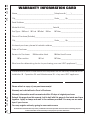
1
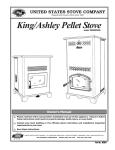
U USSC E STATES ST OV TED NI UNITED STATES STOVE COMPANY “Keeping North America Warm Since 1869” COMPANY Models: 5824 This Pellet heater has been safety tested and listed to ASTM E 1509, ULC/ORD C1482 and ULC-S627, by OMNI-Test Laboratories, Inc. Portland, Oregon, USA. It is also certified and tested to EPA Phase II requirements. Owner’s Manual Please read this entire manual before installation and use of this appliance. Failure to follow these instructions could result in property damage, bodily injury, or even death. Contact your local building or fire officials about obtaining permits, restrictions and installation inspection requirements in your area. Save these instructions. UNITED STATES STOVE COMPANY • 227 INDUSTRIAL PARK ROAD • SOUTH PITTSBURG, TENNESSEE 37380 • WWW.USSTOVE.COM For Customer Service: PHONE: (800) 750-2723 USSC FAX: (423) 837-2109 Email: [email protected] Part No.: 851740 rev G 1 Table of Contents TABLE OF CONTENTS............................................................................................... 2 Warranty registration..................................................................................3-4 Safety Precautions............................................................................................ 5 Specifications........................................................................................................ 6 Heating Specifications.................................................................................................. 6 Dimensions................................................................................................................... 6 Electrical Specifications.................................................................................... 6 Fuel Considerations.......................................................................................... 6 Safety and EPA Compliance............................................................................. 6 Installation . ......................................................................................................... 7 Installation Options........................................................................................... 7 Floor Protection................................................................................................ 7 Clearances ...................................................................................................... 8 Venting Requirements...................................................................................... 9 Maximum Venting Distance.............................................................................. 9 Pellet Vent Type................................................................................................ 9 Pellet Vent Installation...................................................................................... 9 Pellet Vent Termination..................................................................................... 9 Vent Termination Clearances.......................................................................... 10 Through the Wall Installation.......................................................................... 11 Through the Roof/Ceiling Installation............................................................. 11 Outside Air Supply.......................................................................................... 12 Special Mobile Home Requirements.............................................................. 12 understanding your HEATER......................................................................... 13 Operation.........................................................................................................14-15 Start-Up Procedure......................................................................................... 14 Shut Down Procedure..................................................................................... 14 Daily Operation............................................................................................... 15 Safety and Convenience Features................................................................. 15 Maintenance....................................................................................................15-16 Exhaust System.............................................................................................. 15 Interior Chambers........................................................................................... 16 Ash Disposal................................................................................................... 16 Check and Clean the Hopper......................................................................... 16 Main Door Gaskets......................................................................................... 16 Blower Motors................................................................................................. 16 Painted Surfaces............................................................................................ 16 Glass............................................................................................................... 16 Fall Start-Up.................................................................................................... 16 Spring Shut Down........................................................................................... 16 Yearly Servicing.............................................................................................. 16 Trouble Shooting.............................................................................................. 17 Repair Parts Diagram/LIST.........................................................................18-19 Wiring Diagram.................................................................................................... 20 2 USSC CUT HERE " WARRANTY INFORMATION CARD Name__________________________________________ Telephone #: (_____)_____________ City____________________________________________ State_______ Zip_________________ Email Address __________________________________________________________________ Model # of Unit________________________________ Serial #___________________________ Fuel Type: qWood qCoal qPellet qGas qOther _________________________ Place of Purchase (Retailer)______________________________________________________ City____________________________________________ State_______ Zip_________________ If internet purchase, please list website address___________________________________ Date of Purchase _______________________________________________________________ Reason for Purchase: qAlternative Heat qDecoration qCost qMain Heat Source qOther _________________________ What was the determining factor for purchasing your new USSC appliance?_______ I have read the owner’s manual that accompanies this unit and fully understand the: Installation qOperation q and Maintenance q of my new USSC appliance. Print Name Signature Date Please attach a copy of your purchase receipt. Warranty not valid without a Proof of Purchase. " CUT HERE Warranty information must be received within 30 days of original purchase. USSC Detach this page from this manual, fold in half with this page to the inside and tape together. Apply a stamp and mail to the address provided. You may use an envelope if you choose. You may register online by going to www.usstove.com All information submitted will be kept strictly confidential. Information provided will not be sold for advertising purposes. Contact information will be used solely for the purpose of product notifications. 3 CUT HERE " Ê Fold Here Fold Here É Place Stamp Here " 4 CUT HERE United States Stove Company P.O. Box 151 South Pittsburg, TN 37380 USSC Safety Precautions IMPORTANT: Read this entire manual before installing and operating this product. Failure to do so may result in property damage, bodily injury, or even death. Proper installation of this heater is crucial for safe and efficient operation. Install vent at clearances specified by the vent manufacturer. Do not connect the pellet vent to a vent serving any other appliance or heater. Do not install a flue damper in the exhaust venting system of this unit. Use of outside air is not required for this unit. Contact your local building officials to obtain a permit and information on any additional installation restrictions or inspection requirements in your area. Do not throw this manual away. This manual has important operating and maintenance instructions that you will need at a later time. Always follow the instructions in this manual. This heater is designed and approved for premium hardwood pellet fuel only. Any other type of fuel burned in this heater will void the warranty and safety listing. Never use gasoline, gasoline-type lantern fuel, kerosene, charcoal lighter fluid, or similar liquids to start or ’freshen up’ a fire in this heater. Keep all such liquids well away from the heater while it is in use. A working smoke detector must be installed in the same room as this product. Do not unplug the heater if you suspect a malfunction. Turn the heater OFF by pressing and contact your dealer. Your heater requires periodic maintenance and cleaning (see ”MAINTENANCE ”). Failure to maintain your heater may lead to improper and/or unsafe operation. Disconnect the power cord before performing any Soot and Flyash: Formation and Need for Removal - The products of combustion will contain small particles of flyash. The flyash will collect in the exhaust venting system and restrict the flow of the flue gases. Incomplete combustion, such as occurs during startup, shutdown,or incorrect operation of the room heater will lead to some soot formation which will collect in the exhaust venting system. The exhaust venting system should be inspected at least once a month during the heating season to determine if cleaning is necessary. The exhaust system should be checked monthly during the burning season for any build-up of soot or creosote. Do not touch the hot surfaces of the heater. Educate all children on the dangers of a high-temperature heater. Young children should be supervised when they are in the same room as the heater. The hopper and heater top will be hot during operation; therefore, you should always use some type of hand protection when refueling your heater. A power surge protector is required. This unit must be plugged into a 110 - 120V, 60 Hz grounded electrical outlet. Do not use an adapter plug or sever the grounding plug. Do not route the electrical cord underneath, in front of, or over the heater. Do not route the cord in foot traffic areas or pinch the cord under furniture. The heater will not operate during a power outage. If a power outage does occur, check the heater for smoke spillage and open a window if any smoke spills into the room. The viewing door must be closed and sealed during operation. Keep seal in good condition. Never block free airflow through the open vents of the unit. Keep foreign objects out of the hopper. The moving parts of this heater are propelled by high torque electric motors. Keep all body parts away from the auger while the heater is plugged into an electrical outlet. These moving parts may begin to move at any time while the heater is plugged in. Do not place clothing or other flammable items on or near this heater. When installed in a mobile home, the heater must be grounded directly to the steel chassis and bolted to the floor. WARNING—THIS UNIT MUST NOT BE INSTALLED IN THE BEDROOM (per HUD requirements). CAUTION—The structural integrity of the mobile home floor, wall, and ceiling/roof must be maintained. This appliance is not intended for commercial use. maintenance! NOTE: Pressing to switch the unit ”OFF” does not disconnect all power to the electrical components of the heater. Never try to repair or replace any part of the heater unless instructions for doing so are given in this manual. All other work should be done by a trained technician. Do not operate your heater with the viewing door open. The auger will not feed pellets under these circumstances and a safety concern may arise from sparks or fumes entering the room. Allow the heater to cool before performing any maintenance or cleaning. Ashes must be disposed in a metal container with a tight fitting lid. The closed container of ashes should be placed on a noncombustible surface or on the ground, well away from all combustible materials, pending final disposal. * This appliance is a freestanding heater. It is not intended to be attached to any type of ducting. It is not a furnace. USSC 5 Specifications Heating Specifications MInimum Fuel Burn Rate* 1.75 lbs./hr. ±5% Burn Time (lowest setting)* 23 hrs. ±5% Hopper Capacity 40 lbs. * Pellet size may effect the actual rate of fuel feed and burn times. Fuel feed rates may vary by as much as 20%. Use PFI listed fuel for best results. Dimensions Height 33-1/2 in. (851mm) Width 18-1/4 in. (464mm) Depth 19-1/4 in. (489mm) Electrical Specifications Electrical Rating 110-120 volts, 60 HZ, 4.5 Amps Watts (maximum) 520 (approx.) FUEL CONSIDERATIONS Your Pellet heater is designed to burn premium hardwood pellets that comply with Association of Pellet Fuel Industries standards. (Minimum of 40 lbs density per cubic ft, 1/4” to 5/16” diameter, length no greater than 1.5”, not less than 8,200 BTU/lb, moisture under 8% by weight, ash under 1% by weight, and salt under 300 parts per million). Pellets that are soft, that contain excessive amounts of loose sawdust, or that have been or are wet will result in reduced performance. Due to the different fuel densities and sizes, the fuel feed rate may vary. This may require an adjustment to the slider damper setting or the auger feed trim setting on low. Store your pellets in a dry place. DO NOT store the fuel within the installation clearances of the unit or within the space required for refueling and ash removal. Doing so could result in a house fire. SAFETY AND EPA COMPLIANCE Your Pellet heater has been safety tested and listed to ASTM E 1509-04, ULC/ORD C1482-90, and ULC-S627-00 by OMNI-Test Laboratories, Inc. Portland, Oregon, USA. It is also certified and tested to EPA Phase II requirements. 6 USSC Installation Installation Options Read this entire manual before you install and use your pellet heater. Failure to follow instructions may result in property damage, bodily injury, or even death! (See specific installation details for clearances and other installation requirements) A Freestanding Unit—Placed on a non-combustible floor surface in compliance with clearance requirements for a freestanding heater installation. An Alcove Unit—Placed on a non-combustible floor surface in compliance with clearance requirements for an alcove installation. Your heater may be installed to code in either a conventional or mobile home (see SPECIAL MOBILE HOME REQUIREMENTS). Approved for U. S. installation ONLY. It is recommended that only a authorized technician install your heater, preferably an NFI certified specialist. DO NOT CONNECT THIS UNIT TO ANY AIR DISTRIBUTION DUCT OR SYSTEM. IMPROPER INSTALLATION: The manufacturer will not be held responsible for damage caused by the malfunction of a heater due to improper venting or installation. Call (800) 750-2723 and/or consult a professional installer if you have any questions. Floor protection This unit must be installed on a non-combustible floor surface. If a floor pad is used, it should be UL listed or equal. The floor pad or non-combustible surface should be large enough to extend a minimum of 6-inches in front, 6-inches on each side, and 1-inch behind the heater (see FIGURE 1). Floor protection must extend under and 2-inches to each side of the chimney tee for an interior vertical installation (see FIGURE 2). Only an elbow type connection can be used for indoor installation. Your heater will need a minimum 28” (711mm) x 31” (787mm) floor protector. A Floor Protector of 1 inch thick is recommended for this installation. USSC 7 Installation Clearances Your heater has been tested and listed for installation in residential, mobile home, and alcove applications in accordance with the clearances given in FIGURES 3-4 and TABLE 1. NOTE: Distance “D” on the left-hand side of your heater may need to be greater than the minimum required clearance for suitable access to the control panel. FIGURE 3 SIDEWALL / CORNER MINIMUM CLEARANCES PARALLEL CORNER ALCOVE A - Backwall to heater B - Backwall to flue C - Sidewall to flue D - Sidewall to edge of unit E - Adjacent wall to unit F - Alcove depth G - Alcove Hieght Alcove Width 8.00” / 203mm 1.00” / 25mm 7.50” / 191mm 4.00” / 100mm 2.00” / 50mm 25.00” / 635mm 47.00”/ 1194mm 26.50” / 673mm TABLE 1 MINIMUM CLEARANCES (inches/mm) FIGURE 4 MINIMUM ALCOVE CLEARANCES 8 USSC Installation Venting requirements Install vent at clearances specified by the vent manufacturer. Do not connect the pellet vent to a vent serving any other appliance or HEATER. Do not install a flue damper in the exhaust venting system of this unit. The following installation guidelines must be followed to ensure conformity with both the safety listing of this heater and to local building codes. Do not use makeshift methods or compromise in the installation. IMPORTANT! This unit is equipped with a negative draft system that pulls air through the burn pot and pushes the exhaust out of the dwelling. If this unit is connected to a flue system other than the way explained in this manual, it will not function properly. Maximum venting distance Installation MUST include at least 3ft (0.91m) of vertical pipe outside the home. This will create some natural draft to reduce the possibility of smoke or odor during appliance shutdown and keep exhaust from causing a nuisance or hazard by exposing people or shrubs to high temperatures. The maximum recommend vertical venting height is 12ft (3.66m) for 3-inch type “PL” vent. Total length of horizontal vent must not exceed 4ft (1.22m). This could cause back pressure. Use no more than 180 degrees of elbows (two 90-degree elbows, or two 45-degree and one 90-degree elbow, etc.) to maintain adequate draft. Pellet vent type A UL listed 3-inch or 4-inch type “PL” pellet vent exhaust system must be used for installation and attached to the pipe connector provided on the back of the heater (use a 3-inch to 4-inch adapter for 4-inch pipe). Connection at back of heater must be sealed using Hi-Temp RTV. Use 4-inch vent if the vent height is over 12ft (3.66m) or if the installation is over 2,500 feet above sea level. We recommend the use of Simpson Dura-Vent® or Metal-Fab® pipe (if you use other pipe, consult your local building codes and/or building inspectors). Do not use Type-B Gas Vent pipe or galvanized pipe with this unit. The pellet vent pipe is designed to disassemble for cleaning and should be checked several times during the burning season. Pellet vent pipe is not furnished with the unit and must be purchased separately. Pellet vent installation The installation must include a clean-out tee to enable collection of fly ash and to permit periodic cleaning of the exhaust system. 90-degree elbows accumulate fly ash and soot thereby reducing exhaust flow and performance of the heater. Each elbow or tee reduces draft potential by 30% to 50%. All joints in the vent system must be fastened by at least 3 screws, and all joints must be sealed with Hi-Temp RTV silicone sealant to be airtight. The area where the vent pipe penetrates to the exterior of the home must be sealed with silicone or other means to maintain the vapor barrier between the exterior and the interior of the home. Vent surfaces can get hot enough to cause burns if touched by children. Noncombustible shielding or guards may be required. Only an elbow type connection can be used for indoor installation. The chimney connector shall not pass through an attic or roof space, closet or similar concealed space, or a floor, or ceiling. Pellet vent termination Do not terminate the vent in an enclosed or semi-enclosed area, such as; carport, garage, attic, crawl space, under a sundeck or porch, narrow walkway, or any other location that can build up a concentration of fumes. The termination must exhaust above the outside air inlet elevation. The termination must not be located where it will become plugged by snow or other materials. Do not terminate the venting into an existing steel or masonry chimney. USSC 9 Installation Vent termination clearances: A) Minimum 4-foot (1.22m) clearance below or beside any door or window that opens. B) Minimum 1-foot (0.3m) clearance above any door or window that opens. C) Minimum 3-foot (0.91m) clearance from any adjacent building. D) Minimum 7-foot (2.13m) clearance from any grade when adjacent to public walkways. E) Minimum 2-foot (0.61m) clearance above any grass, plants, or other combustible materials. F) Minimum 3-foot (0.91m) clearance from an forced air intake of any appliance. G) Minimum 2-foot (0.61m) clearance below eves or overhang. H) Minimum 1-foot (0.3m) clearance horizontally from combustible wall. I) Must be a minimum of 3 foot (0.91m) above the roof and 2 foot (0.61m) above the highest point or the roof within 10 feet (3.05m). G FIGURE 5 VENT TERMINATION CLEARANCES 10 USSC Installation THROUGH THE WALL INSTALLATION (Recommended installation) Canadian installations must conform to CAN/CSA-B365. To vent the unit through the wall, connect the pipe adapter to the exhaust motor adapter. If the exhaust adapter is at least 18 in.(457mm) above ground level, a straight section of pellet vent pipe can be used through the wall. Your heater dealer should be able to provide you with a kit that will handle most of this installation, which will include a wall thimble that will allow the proper clearance through a combustible wall. Once outside the structure, a 3 in.(76mm) clearance should be maintained from the outside wall and a clean out tee should be placed on the pipe with a 90-degree turn away from the house. At this point, a 3ft (0.91m) (minimum) section of pipe should be added with a horizontal cap, which would complete the installation (see FIGURE 6). A support bracket should be placed just below the termination cap or one every 4ft (1.22m) to make the system more stable. If you live in an area that has heavy snowfall, it is recommended that the installation be taller than 3ft (0.91m) to get above the snowdrift line. This same installation can be used if your heater is below ground level by simply adding the clean-out section and vertical pipe inside until ground level is reached. With this installation you have to be aware of the snowdrift line, dead grass, and leaves. We recommend a 3ft (0.91m) minimum vertical rise on the inside or outside of the house. FIGURE 6 TYPICAL THROUGH THE WALL INSTALLATION The “through the wall” installation is the least expensive and simplest installation. Never terminate the end vent under a deck, in an alcove, under a window, or between two windows. We recommend Simpson Dura-Vent® or Metal-Fab® kits. Through the roof/Ceiling Installation When venting the heater through the ceiling, the pipe is connected the same as through the wall, except the clean-out tee is always on the inside of the house, and a 3 in.(76mm) adapter is added before the clean-out tee. You must use the proper ceiling support flanges and roof flashing (supplied by the pipe manufacturer; follow the pipe manufacturer’s directions). It is important to note that if your vertical run of pipe is more than 15ft (4.57m), the pellet vent pipe size should be increased to 4 in. (102mm) in diameter. Do not exceed more than 4ft (1.22m) of pipe on a horizontal run and use as few elbows as possible. If an offset is required, it is better to install 45-degree elbows rather than 90-degree elbows. USSC 11 Installation Outside Air Supply (optional, unless installing in a mobile home) Depending on your location and home construction, outside air may be necessary for optimal performance. Metal pipe (solid or flexible) must be used for the outside air installation. PVC pipe is NOT approved and should NEVER be used. A wind shield over the termination of the outside air pipe or a 90-degree elbow or bend away from the prevailing winds MUST be used when an outside air pipe is installed through the side of a building. The outside air termination MUST be at least 1ft (0.305m) away from the exhaust system termination. The outside air pipe on your heater is 2” (50.8mm) OD. The outside air connecting pipe must be at least 2” (50.8mm) ID. The outside air connection used MUST NOT restrict the amount of air available to your heater. The outside air connecting pipe must be as short and free of bends as possible, and it must fit over, not inside, the outside air connection to the heater. FIGURE 8 TYPICAL FRESH AIR TERMINATION FIGURE 7 EXHAUST/INLET LOCATIONS NOTE: Dimensions from the floor to your heaters inlet/exhaust pipes are approximate and may vary depending on your installation. Special Mobile Home Requirements WARNING! - Do not install in a sleeping room CAUTION! - The structural integrity of the mobile home floor, wall, and ceiling/roof must be maintained. In addition to the previously detailed installation requirements, mobile home installations must meet the following requirements: • The heater must be permanently attached to the floor. • The heater must be electrically grounded to the steel chassis of the mobile home with 8 GA copper wire using a serrated or star washer to penetrate paint or protective coating to ensure grounding. • Vent must be 3 or 4-inch “PL” Vent and must extend a minimum or 36 in.(914mm) above the roof line of the mobile home and must be installed using a UL listed ceiling fire stop and rain cap. • When moving your mobile home, all exterior venting must be removed while the mobile home is being relocated. After relocation, all venting must be reinstalled and securely fastened. • Outside Air is mandatory for mobile home installation. See your dealer for purchasing. • Check with your local building officials as other codes may apply. 12 USSC Understanding your heater How your heater works Your heater utilizes a vertical auger fuel feed system that is operated by a microprocessor controlled digital circuit board. The digital circuit board allows the vertical auger fuel feed system to run in a timer-based, non-continuous cycle; this cycling allows the auger to run for a predetermined period of seconds. The auger pushes pellets up a chute located in the hopper which in turn falls through another chute into the burnpot. Your heater is equipped with an automatic ignition system that should ignite the fuel within 3 - 5 minutes from pressing the button. As pellets enter the burnpot and ignite, outside air is drawn across the fuel and heated during the combustion process which is then pulled through the heat exchanger by the exhaust motor or draft fan. As the heater heats up, room air is circulated around the heat exchanger by means of a room air blower, distributing warm air into the room. The amount of heat produced by the heater is proportional to the rate of the fuel that is burned, and this rate is controlled . In order to maintain combustion of the fuel at a desired rate, the air provided to the burn chamber by the exhaust or draft fan must be maintained precisely. Too little air will result in a flame that is nonenergetic or lazy. If the fuel continues to flow with too little air for long enough, the burn pot will fill with too much fuel and the fire will smother out. To much air will result in a flame that is overactive or aggressive. The flame in this situation is typically very blue at the bottom and resembles a blow torch. If this situation continues, the fuel in the burn pot will be consumed and the fire will go out. by the Fuel Control button Matching the amount of air required for proper combustion to the fuel rate is the primary objective in effectively burning pellets of various brands and qualities in your heater. The air to fuel ratio can be adjusted to allow almost any fuel quality to burn effectively by following the procedures detailed in the remainder of this manual. Because a forced draft pressure is required for the combustion process inside your heater, it is extremely important that the exhaust system be properly installed and maintained. And, that when operating your heater, you make sure that the viewing door is properly sealed. FIGURE 9 DIGITAL CONTROL PANEL USSC 13 Operation START-UP PROCEDURE DO NOT USE CHEMICALS OR FLUIDS TO START THE FIRE - Never use gasoline, gasoline-type lantern fuel, kerosene, charcoal lighter fluid, or similar liquids to start or “freshen up” a fire in this heater. Keep all such liquids well away from the heater while it is in use. DO NOT BURN GARBAGE OR FLAMMABLE FLUIDS SUCH AS GASOLINE, NAPHTHA, OR ENGINE OIL. HOT WHILE IN OPERATION. KEEP CHILDREN, CLOTHING AND FURNITURE AWAY. CONTACT MAY CAUSE SKINS BURNS. 1.) Verify that the hopper is clean and free of foreign matter including pellet fines and dust. 2.) Verify that all of the required exhaust/inlet connections have been made in accordance with this manual and that the heater is plugged into an outlet (an outlet surge protector is highly recommended). 3.) Fill the hopper with wood pellets; do not allow any part of the bag or any other foreign material into the hopper, as this may jam the auger. 4.) Ensure that all pellet matter is cleared from the hopper seating surface. 5.) Close the hopper lid. The unit WILL NOT feed fuel with the hopper lid open. 6.) Make sure that the viewing door is securely closed (the safety pressure switch will not allow the heater to feed fuel if there is no draft pressure inside the heater). 7.) Press the button on the control pad and then select the highest heat range by pressing the button. 8.) The heater will begin to feed fuel and the auto-start ignitor will ignite the fuel in approximately 3 to 5 minutes. When starting the unit for the first time, the auger mechanism will not be primed with pellets. This will cause the auto-start ignitor to time out and shut the unit down. Pressing the button again will restart the startup sequence and the heater should ignite properly. However, on some occasions, this process may need to be repeated until ignition depending on fuel size and quality. As an alternative method to the initial startup, prior to step 6 above, you may add a handful of pellets or add pellets up to the ignition port in the burnpot. DO NOT fill the burnpot full with pellets. Proceed to step 6 thru 8. The pellets should ignite and heater begin proper operation. Once a consistent flame has been established, you can adjust the heat range on the control pad to your desired setting, low, medium, or high. (Note: The distribution blower will not function until the heat exchanger in the heater reaches the factory preset temperature). First Fire: Adjust the heat range to a medium setting and allow the heater to operate in this manner for approximately three (3) hours (or more if necessary), allowing the heater to “cure out” as the paint and oils from the manufacturing process burn off. We recommend that you open doors and windows in your home during this process. Then adjust heat range to your desired setting. SHUT DOWN PROCEDURE WARNING: Never shut down this unit by unplugging it from the power source. Press the button on the control pad to put the heater in shut down mode. Once this is done, the auger will stop feeding pellets, but the distribution blower and exhaust blower will continue to operate. When the internal temperature of the unit drops below the factory preset temperature, the distribution blower and exhaust blower will cease to operate and the unit will be completely shut down. The hotter the unit is during its operation, the longer it will take for the heater to complete the shut down cycle. If the heater stays on for more than 2 hours after pressing the button and you are sure that the fire is out, the heater can be unplugged from the outlet. After approximately 10 seconds, the unit can be re-connected to the power source and the control board will be reset. If a chimney or creosote fire occurs, press the 14 button immediately. Do not unplug the unit. USSC Operation DAILY OPERATION The hopper and heater top will be hot during operation; therefore, you should always use some type of hand protection when refueling your heater. Never place your hand near the auger while the heater is in operation. In the event of a power outage, the heater will not function. It is very important that unit be vented properly (with outside air), as the natural draft is needed to clear the smoke from the heater during a power outage. If the unit was ON when the power outage occurred, one of the following will take place: 1.) If the heater is still warm, it will resume feeding fuel and continue to operate normally. If the fire has gone out, you will have to press the button and then the button again to begin a new start-up sequence. 2.) If the heater has cooled-off, it will reset to its OFF condition. At this point, you may press the unit will begin a new start-up sequence. button and the NOTE: The unit will also shut down in the event of an exhaust blower failure; if this is the case, the unit will not re-start and you must contact Customer Service at (800) 750-2723. safety and Convenience features Your heater includes an auto-start igniter as a standard feature. The use of other fire starter materials (wood chips, starter gel, etc.) is not necessary. By simply pressing the to feed fuel and automatically start within 3 to 5 minutes. button on the digital control panel, your heater will begin For safety, this heater incorporates a safety pressure switch that helps ensure that everything is in proper working order before feeding fuel to the burn pot. Because the heater works using an induced draft pressure, the heater will not continue to operate if the viewing door is left open; or if the exhaust blower fails or the exhaust system is blocked. The temperature limit control (Thermodisc) will prevent your heater from operating at abnormally high temperatures. Should the heater temperature reach the factory pre-set limit, 200°F(93°C), the temperature limit control will automatically stop the auger feed rate until the temperature returns to a normal condition. Maintenance Failure to clean and maintain this unit as indicated can result in poor performance and safety hazards. Unplug your heater’s electrical cord prior to removing the back panel or opening the exhaust system for any inspection, cleaning, or maintenance work. Never perform any inspections, cleaning, or maintenance on a hot heater. Do not operate heater with broken glass , leakage of flue gas may result. Exhaust System Creosote Formation – When any wood is burned slowly, it produces tar and other organic vapors, which combine with expelled moisture to form creosote. The creosote vapors condense in the relatively cool chimney flue or a newly started fire or from a slow-burning fire. As a result, creosote residue accumulates on the flue lining. When ignited, this creosote makes an extremely hot fire, which may damage the chimney or even destroy the house. Despite their high efficiency, pellet heaters can accumulate creosote under certain conditions. Fly Ash – This accumulates in the horizontal portion of an exhaust run. Though non-combustible, it may impede the normal exhaust flow. It should therefore be periodically removed. Inspection and Removal – The chimney connector and chimney should be inspected annually or per ton to determine if a creosote or fly ash build-up has occurred. If creosote has accumulated (3mm or more), it should be removed to reduce the risk of a chimney fire. Inspect the system at the heater connection and at the chimney top. Cooler surfaces tend to build creosote deposits quicker, so it is important to check the chimney from the top as well as from the bottom. The creosote should be removed with a brush specifically designed for the type of chimney in use. A qualified chimney sweep can perform this service. It is also recommended that before each heating season the entire system be professionally inspected, cleaned and, if necessary, repaired. To clean the chimney, disconnect the vent from the heater. USSC 15 Maintenance Interior Chambers Periodically remove and clean the burnpot and the area inside the burnpot housing. In particular it is advisable to clean out the holes in the burnpot to remove any build up that may prevent air from moving through the burn pot freely. If a vacuum is used to clean your heater, we suggest using a vacuum designed for ash removal. Some regular vacuum cleaner (i.e. shop vacs) may leak ash into the room. Ash Disposal Ashes should be placed in a metal container with a tight fitting lid. The closed container of ashes should be placed on a noncombustible floor or on the ground, well away from all combustible materials, pending final disposal. If the ashes are disposed of by burial in soil or otherwise locally dispersed, they should be retained in the closed container until all cinders have been thoroughly cooled. The container shall not be used for other trash or waste disposal. Check and Clean the Hopper Check the hopper periodically to determine if there is any sawdust or pellets that are sticking to the hopper surface. Clean as needed. Door and glass Gaskets Inspect the main door and glass window gaskets periodically. The main door may need to be removed to have frayed, broken, or compacted gaskets replaced by your authorized heater dealer. Blower Motors Clean the air holes on the motors of both the exhaust and distribution blowers annually. Remove the exhaust blower from the exhaust duct and clean out the internal fan blades as part of your fall start-up. Painted Surfaces Painted surfaces may be wiped down with a damp cloth. If scratches appear, or you wish to renew your paint, contact your authorized heater dealer to obtain a can of suitable high-temperature paint. GLASS - Cleaning, Removal and Replacement of Broken Door Glass Cleaning - We recommend using a high quality glass cleaner. Should a build up of creosote or carbon accumulate, you may wish to use 000 steel wool and water to clean the glass. DO NOT use abrasive cleaners. DO NOT perform the cleaning while the glass is HOT. , In the event you need to replace the glass, remove the six(6) screws and glass retainers. While wearing leather gloves (or any other gloves suitable for handling broken glass), carefully remove any loose pieces of glass from the door frame. Dispose of all broken glass properly. ONLY high temperature, ceramic glass of the correct size(10.25[261] x 11.06[281] in[mm]) and thickness(5mm) may be used. DO NOT substitute alternative materials for the glass. Contact your authorized dealer to obtain this glass. Re-install the new glass by re-attaching the retainers and screws, careful not to overtighten the screws for this could damage the glass. DO NOT abuse the door glass by striking, slamming or similar trauma. Do not operate the heater with the glass removed, cracked or broken. FALL START UP Prior to starting the first fire of the heating season, check the outside area around the exhaust and air intake systems for obstructions. Clean and remove any fly ash from the exhaust venting system. Clean any screens on the exhaust system and on the outside air intake pipe. Turn all of the controls on and make sure that they are working properly. This is also a good time to give the entire heater a good cleaning throughout. SPRING SHUTDOWN After the last burn in the spring, remove any remaining pellets from the hopper and the auger feed system. Scoop out the pellets and then run the auger until the hopper is empty and pellets stop flowing (this can be done by pressing the “ON” button with the viewing door closed). Vacuum out the hopper. Thoroughly clean the burnpot, and firebox. It may be desirable to spray the inside of the cleaned hopper with an aerosol silicone spray if your heater is in a high humidity area. The exhaust system should be thoroughly cleaned. 16 USSC Trouble Shooting Disconnect the power cord before performing any maintenance! NOTE: Pressing the OFF button does not disconnect all power to the electrical components of the heater. Never try to repair or replace any part of the heater unless instructions for doing so are given in this manual. All other work should be done by a trained technician. PROBLEM CAUSE: Lack of combustion air intake. Orange / lazy flame, excessive fuel build-up in the burnpot • Clean out the burnpot. • Make sure that the viewing door is closed and sealed properly. If not, check or replace door gaskets. • Check that all outside connections are clear of any obstructions. • Check the exhaust system; clean as needed. PROBLEM CAUSE: Burnpot burns out of fuel Fire goes out or heater shuts down. A. Three lights are bright and flashing. A. Auger system is jammed or there is a “bridging” of the fuel in the hopper, preventing fuel from flowing into the auger feed system. Check that the Auger motor is functioning. Check wiring and the auger to motor connection. B. Three lights are bright but not flashing B. Hopper is empty, refill the hopper. C. The RED light is bright and flashing, but the other are not. C. The high temperature thermodisc has tripped. Check the wiring connections. Possibly replace thermodisc. D. Three lights are not bright. D. Loss of power. Other possible causes/solutions: • Loss of draft pressure. Make sure that the viewing door is closed and sealed properly. If not, check and/or replace door gaskets. Check that all outside connections are clear of any obstructions. Check the exhaust system; clean as needed. • Check that the pressure switch connection to the firebox is free of ash or clear of obstructions. PROBLEM CAUSE: No power or Auto-Start Igniter fails to ignite the fuel in the burnpot. Heater does not start a fire when the ton is pushed but- • Make sure power is supplied to heater. • Turn the heater OFF. Clear the unburnt fuel from the burnpot and try again. • Check the pellet quality. Replace if moist, wet, or dirty. • Loss of draft pressure. Make sure that the viewing door is closed and sealed properly. If not, check and/or replace door gaskets. Check that all outside connections are clear of any obstructions. Check the exhaust system; clean as needed. • Check that the pressure switch connection to the firebox is free of ash or clear of obstructions. • Check that the auto-start igniter is not blocked with ash or soot. • The auto-start igniter gets “red hot” during start-up. If you can not visibly see the igniter glowing during start-up, then the igniter may need to be replaced or there is a problem with the electrical control system. PROBLEM CAUSE: Heater is overheating. The heater has been working too long or room temp. is too high Two lights are bright, the feeding light is off, and meanwhile the orange light is bright • Allow heater to shutdown automatically, then restart. PROBLEM A. Heater does not start when CAUSE: The burnpot is positioned incorrectly. is pressed. • Put burnpot in correct position, as indicated by the slot on the burnpot. B. Prolonged ignition time with excess smoke. C. Burning is not active. USSC 17 Parts Diagram 18 USSC Parts List 5824 Item Part No. TitleQty. Item Part No. TitleQty 1 A B C D E F G 2 3 4 5 6 7 8 9 10 11 12 13 14 15 16 17 18 19 20 21 22 23 24 25 USSC 891603 891604 891605 891606 88139 88140 891607 88141 891608 891609 891610 891611 891612 891613 891614 891615 891616 891617 891618 891619 80562 891620 891621 891622 891623 891624 891625 891626 891627 891628 891629 891630 Door Frame Assy. (5824-05-01-00) Door Frame Wldmt (5824-05-00) Nylon Shim (5824- 08-01) Door Hndle Wldmt (5824-05-02-00) Glass Gasket (5824-09-00) Glass (5824-05-04) Glass Retainer (5824-05-01-09) Door Gasket (5824-08-00) Firebox Frt. Panel (5824-01-01-13) Door Hook Pin (5824-01-15) Hook Pin Tube (5824-01-16) Side Wall Panel (5824-08) Left Wall Panel (5824-09) Ash Pan Weldment (5824-01-02-00) Burnpot Support (5824-01-01-04) Burnpot (5824-01-10-00) Air-In Grid (5824-07-00) Air-Out Grid (5824-06-00) Insulation Cover (5824-01-03) Top Panel Assy. (5824-03-00) Microswitch (5824-19-00) Micro-sw Hsg-1 (5824-03-01-03-01) Micro-sw Hsg-2 (5824-03-01-03-02) Top Insulation Panel (5824-01-06) Top Air Guide Cover (5824-01-07) Support, Top Air Guide (5824-01-05) Maintenance Panel (5824-01-17) Upper Hinge (5824-01-11-01) Uppr Hng Fixing Pin (5824-01-11-02) Lower Hinge (5824-01-12) Lower Hinge Pin (5824-01-14) Hinge Sleeve (5824-01-13) 1 1 1 1 1 1 2 1 1 1 1 1 1 1 1 1 1 1 1 1 1 1 1 1 1 2 1 1 1 1 1 1 26 27 28 29 30 31 32 33 34 35 36 37 38 39 40 41 42 43 44 45 46 47 48 49 50 51 52 53 54 N/S N/S N/S 80563 891631 891632 891633 80564 891634 891635 891636 80565 80566 891637 891638 891639 891640 80567 891641 891642 80568 80569 80570 891643 80571 80572 891644 891645 891646 891647 891648 891649 891675 891685 891686 Distribution Motor Assy (5824-11-00) 1 Firebox Weldment (5824-01-01-00) 1 Vent Slides (5824-01-18) 1 Ignitor Sleeve (5824-02-12) 1 Ignitor Assembly (5824-21-00) 1 Exhaust Hsg Wld (5824-01-01-11-00) 1 Exhast Maint. Cover (5824-01-16-01) 1 Smoke Weldment (5824-01-09-00) 1 Exhaust Motor Assy (5824-01-08) 1 125°F(52°C) Sensor (5824-22-00) 2 Hopper Frame (5824-02-01-00) 1 L/R Wiring Guide Rail (5824-02-03) 2 Back Wiring Guide Rail (5824-02-04) 1 Back Panel (5824-10) 1 Pressure Switch (5824-20-00) 1 Support Pressure Sw. (5824-02-06) 1 Insulation Panel (5824-01-04-01) 1 198°F(92°C) Sensor (5824-23-00) 1 Circuit Board (5824-18-00) 1 Power Supply Box (5824-17-00) 1 Support, Pwr Sply Box (5824-02-05) 1 Capacitance (5824-16-00) 1 Motor (5824-15-00) 1 Feed Tube Wldmt (5824-02-02-01-00) 1 Support, Motor (5824-02-02-01-09) 1 Feed Tube Cover (5824-02-02-01-04) 1 Big Bearing (5824-11-00) 1 Small Bearing (5824-13-00) 1 Auger Weldment (5824-02-02-01-05) 1 Vermiculite Board Front W/Cutout 1 Vermiculite Board Front Top 1 Vermiculite Board Sides 2 19 Wiring Diagram How to Order Repair Parts This manual will help you obtain efficient, dependable service from your heater, and enable you to order repair parts correctly. Keep this manual in a safe place for future reference. When writing, always give the full model number which is on the nameplate attached to the heater. When ordering repair parts, always give the following information as shown in this list: 3. The model number:____________________ 4. The serial number:____________________ 20 STATES ST OV TED NI USSC E 2. The part description U 1. The part number COMPANY United States Stove Company 227 Industrial Park Road P.O. Box 151 South Pittsburg, TN 37380 (800) 750-2723 WWW.USSTOVE.COM USSC