1
H ©ten)£]@Gr
r
Field Service Manual
and
Parts Catalog
PART NO. 25238806
SECOND EDITION
WARNING:
This equipment generates, uses, and can radiate radio frequency energy and if not Installed
and used In accordance with the instructions manual, may cause interference to radio
communications. It has been tested and found to comply with the limits for a Class A
computing device pursuant to Subpart J of Part 15 of FCC Rules, which are designed to
provide reasonable protection against such Interference when operated in a commercial
environment. Operation of this equipment In a residential area Is likely to cause interference In
which case the user at his own expense will be required to take whatever measures may be
required to correct the interference.
*>
CHANGER WARRANTY
Rowe extends the original operator of this equipment the following warranty:
All parts are guaranteed to be free of defects in material and workmanship for the specific periods which follow. Rowe agrees to repair
without charge during such period any part which proves defective upon examination by Rowe. All costs of shipping an allegedly defective
part to Rowe's offices shall be borne by the original operator. Rowe will pay the shipping costs for the replacement of defective parts
Coin Hoppers
5 Years From Date of Purchase
Electrical Circuit Boards
1 Year From Date of Purchase
Electrical and Mechanical Parts
1 Year From Date of Purchase
Lamps
90 Days From Date of Purchase
In the case of parts supplied to Rowe as components. Rowe extends the same warranty period as extended by the original manufacturer.
The above warranty applies provided that all parts of the product have been serviced properly as directed in the service manual, and
provided the alleged defective part, upon examination by Rowe. shall prove to be thus defective. Under no circumstances shall Rowe be
liable for any incidental, consequential or special damages, losses or expenses arising from or in connection with the use of. or the inability
to use. the product for any purpose. Rowe reserves the right to make any changes or improvements in its products without notice and
obligation, and without being required to make corresponding changes or improvements in products theretofore manufactured or sold.
This warranty will not apply to any part which has been subjected to any accident, abuse, or misuse.
ROWE INTERNATIONAL, INC. EXTENDS NO WARRANTY, EXPRESSED OR IMPLIED, TO PURCHASERS
OR USERS OF ITSPRODUCTS EXCEPT AS HEREIN SET FORTH, WHETHER BY OPERATION OF LAW OR
OTHERWISE.
Tear along this line
3
0
>
CO
c
>
I-
>
m
2
O
33
£.
o
CO
m
2
Z
o
TJ
>
"0
c
Z
a
o
2
m
m
CO
m
•n
O
33
m
Ol
o
o
CO
z
CO
GO
£fc
O
33
CO
H
O
>
CO
CD
?
5'
m
>
m
I"
ct
>
CD
u
S
"5
m
ct
CO
o
3
0)
•••
H
<
07
c
0)
O
o
z
H
33
•MB
<
m
—L
"n
o
CO
H
>
3
Q)
>
CD
ai
o
-o
§
Q
33
r-
U
•o
m
a
•<
3
>
Z
H
o
a
33
•
fO
m
CO
m
z
m
0)
CO
STED INTH
jj
m
•u
D
r-
>
•<
Z
O
I-
>
MAIL
z
CES POST
o
3)
S
2
>
«•
•••••
•••
•
3
i
3
O
O
r
c
V
z
H
zz
-n m O
> m m > >
H
o 33 q
m
< m
CO
>
o
m
33
Serial No.
Number
State
Company_
Excellent
Z'P.
Date
Good
Fair
03
03
and/or set up, please advise In the space provided below.
If there are any suggested product Improvements orif problems areencountered during Installation
The operation manual and Instructions are:
The distributor suppport lor this product was:
The overall quality ol this product was:
This products performance when first powered up was:
Please complete the following:
Product Purchased From
Model No.
Telephone: Area Codo
City
Street Address_
Name
This card completed by:
c
Field Service Manual
and
Parts Catalog
1500 UNION AVE, SE • GRAND RAPIDS. W 40507-11
(616)2434633
Printed In USA
FORWARD
This service manual is divided into she sections:
• Section 1
System Description — Introduces you to the BC-150, its features, and its major
components, principles of operation, and capacities
• Section 2
• SecH0n3
Installation And Programming — Guides you through step-by-step installation
instructions and detailed setup (programming) procedures.
Routine Service — Pmvidea mirHng urnrte* <n«h-m«Hfing far ggngral TTia<nti*naTOH* anrj
preventive maintenance. This section provides information for routine service and
Identified problems. Refer to Section 4, Troubleshooting, for procedures and
techniques to identify a malfimctlon or reject problem.
• Section 4
Troubleshooting — Provides troubleshooting charts, detailed error message
descriptions, troubleshooting procedures, a block diagram, schematics, circuit
board layouts, and component lists. This section also contains a detailed sequence
of operation.
• Sections
Miscellaneous — Contains a resistor color code chart, a harness color code list, and
other miscellaneous information.
• Section 6
The PartsCatalog — Lists and illustrates aU replaceable modules in the BC-150.
This manual is intended for owners, route operators, and t™»1'lTri'»teTlg This manual provides aU field
and shop related service and maintenance material. Accessories and their installation and service are
discussed in the corresponding accessory instructions (or manuals).
Table of Contents
SECTION 1 -
SYSTEM DESCRIPTION
Introduction
1-1
General Operation
Changing A Bill
Functional Description .
Bill Transport
Single Bill Stacker
Dispenser
Hopper
Machine Capacities
Temporarily Out Of Service Lamp
1-1
1-1
1-2
1-2
1-3
1-4
1-5
1-5
1-5
EMI Filter
Power Control Center
1-5
1-6
Dollars Accepted Counter
Power Supply
1-6
1-6
Test Switches
1-7
Power Control Relay
Changer Control Computer
Status Display
Service And Control Switches
1-7
1-7
1-8
1-8
Programming/Normal
Denominations Accepted
1-8
1-9
Coin Control
1-9
0^
SECTION 2 -
INSTAUATION AND PROGRAMMING
Installation
2-1
BC-150 Mounting Techniques
Mounting The BC-150 On A Wall
Mounting The BC-150 On A Table Or A Shelf
Change Payout Programming
Loading The Hopper
Unloading The Hopper
Operational Information
Setting Up The BC-150
Key Information
Turning The Power On
2-1
2-1
2-1
2-2
2-3
2-3
2-4
2-5
2-5
2-5
Switching To The Programming Mode
2-5
If No Access Code Has Been Established
2-6
If An Access Code Has Been Established
To Program A Different Access Code
Self Diagnostics
Diagnostic Check
Fault Message Check
Status Messages
Bill Acceptance Messages
2-6
2-6
2-9
2-9
2-9
2-9
2-9
Transport Self-Clear Check
Acceptance Check
Miscellaneous
!. 2-9
2-10
2-10
III
Table of Contents
SECTION 3 -
ROUTINE SERVICE
Introduction
3.1
Removing A Jammed Bin From The Bill Acceptor
BBI Jamming Check List
Cleaning The Hopper Coin Path
Change Bucket Lubrication
Test Procedures
Transport Motor Speed Check
3-1
3-1
3-2
3-3
3-3
3-3
Testing BC-150 Transport Photocells
VI - Transport Inlet
VF - Ripper Cell
VT - Transmissive Cell
VR - Reflective Cell
Adjustments
Hopper Chain Adjustment
Bill Stacker
Timing Belt Tension
SECTION 4 -
TROUBLESHOOTING
introduction
Power Up Diagnostics
Sequence Descriptions
Machine Status
Standby Mode
Accept, Payout, And Replenish Modes
Reject Mode
Index To Error Messages And Troubleshooting Charts
Validation Rejects
Cell Sequence Rejects
BBI Parameter Rejects
Transport Errors
Clearing Errors
Machine Errors
Clearing Machine Errors
Coin Detector Errors While In Standby Mode
Detailed CCC Board Operation
Control Computer
Reset Circuit
Address And Data
I/O Ports
Digital Display Diver
Output Circuits
4-1
4-1
4-2
4-2
4-4
4-6
4-6
4-16
4-19
4-19
4-22
4-22
4-24
4-41
4-41
4-42
4-42
4-42
4-42
4-43
4-43
4-43
LED Drive
4-43
Out Of Service Lamp
4-43
Stacker Drive
4-44
Input Circuits
-^
^
4-2
4-3
4-3
Transport Motor Control
Hopper Motor Control
Dollar Counter
Iv
3-4
.3-4
3-4
3*4
3-4
3-5
3-5
3-6
3-6
4-44
,
^
Table of Contents
SECTION 5 -
ADDITIONAL INFORMATION
Resistor Color Code Chart
5-1
Harness Color Coding
5-2
SECTION 6 -
PARTS CATALOG
BC-150 Order Options Sheet
6-2
Introduction
6-3
Catalog Description
Parts List Description
Ordering Replacement Parts
Parts Catalog
6-3
6-3
6-3
6-5
FREQUENTLY USED FIGURES AND TABLES
Capabilities, Machine (Table 1-2)
1-5
Diagrams
BA-50 Transport (Figure 4-4)
BC-150 Wiring Diagram (Figure 4-1)
BC-150 Schematic (Figure 4-2)
Computer Control Board (CCC) (Figure 4-6)
Driver Circuit Board Schematic (Figure 4-7)
Magnetic Amplifier Board (Figure 4-5)
Power Supply (Figure 4-3)
.-
4-55
4-47
4-49
4-61
4-73
4-57
4-51
Hopper
Chain Adjustment (Figure 3-4)
Value Codes (Table 2-3)
3.5
2-7
Money Accepted (Table 2-4)
2-8
Power Control Center (Figure 1-7)
1-6
Resistor Color Code Chart (Figure 5-1)
5-1
Transport
Check Points (Figure 3-1)
3-2
View
Bottom (Figure 1-3)
Top (Figure 1-2)
1-3
1-2
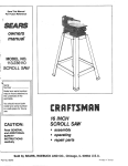
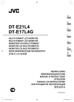
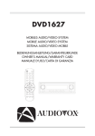
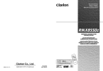
Coin Hopper Holds Quarters, SBA $1 Coins
or tokens. An optional hopper
can be used for nickels or
dimes.
Computer Control
Center (CCC) Controls
validation
and
change making functions. Also
contains the status display,
the function switches (keys)
and
the
PROGRAM/NORMAL
switch.
Coin Dispenser
(behind hopper) •
Contains drive motor and coin
counting
photocell,
for
dispensing change.
Bill Transport Receives
the
bill
that
is
inserted by the customer and
moves
the
bill - into
the
machine.
Contains sensors
which are used to determine
the validity and denomination
of the bill tf the bill is deter
mined to be valid, it is
delivered to the stackerotherwise, it is returned to the
customer.
Bill Stacker -
Receives and stacks bills into
bifl box.
Power Control Center -
Contains the dollars accepted
counter, circuit breakers, on/off
switch, step-down transformer,
power relay, voltage regulator,
and power supply circuit board.
Figure 1-1. BC-150 Major Components
vi
Section 1: System Description
INTRODUCTION
The Rowe BC-150 Bin Changer is specially designed for casinos. It uses the same computer and money
changer technology used in our other changer models, which combines Rowe quality and reliability with
maximum flexibility and ease of Installation and service.
The BC-150 accepts and dispenses change for combinations of 1. 2. 5. 10. and 20 dollar bills of United
States currency. Denominations can be programmed to be accepted In any combination, as can the
choice of coins paid out.
• A microcomputer in the bill Changer Control Computer (CCC) selectively discriminates between
denominations, provides protection against bogus bills and controls the change dispensing
functions.
• Plug-in circuits and assemblies are featured for fast field substitution.
• Coin combination and acceptable denomination programming is easily changed using the FUNCTION,
UP, DOWN, VALUE and HOPPER pushbutton switches.
• The removable coin hopper permits rapid bulk inarfiTig of coins.
• During setup, a special payout check feature ensures that the payout amount selected matches the
denomination accepted.
• Optional coin control may be programmed to monitor the number ofcoins left in the changer, which
prevents shortages to the customer.
Refer to figure 1-1 for the locations of the major BC-150 components.
GENERAL OPERATION
The entire validation and payout sequence is controlled by a microcomputer to ensure the Trunrtrmim
security against bogus currency and Jackpottmg. Refer to the Detailed Computer Board Operation 1n
Section 4 for a complete explanation of how the marfotru*works.
Changing A Bill
Inserting a dollar bill in the transport starts a motorwhich moves the bin along the aooppt"^tr?ok, While
in motion, the bill is examined to determine whether or not it is valid (during this time, the message
VALIDATING win appear on the computer's display).
If the bill is valid, a vend signal is transmitted to the dispenser and the bill drops into the bin stacker
where it is stacked flat against other valid bills. At this time, the message PAY $1 (for example) for a $1
bin will appear on the display.
The coin hopper motorthen operates, dropping the correct number of coins from the coin hopper into the
coin cup.
Ifthe bill is determined to be invalid, the bill transport motor reverses, returning the bin to the customer.
25238806
M
8C-150
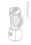
FUNCTIONAL DESCRIPTION
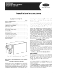
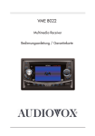
This functional description can be used to gam an oveiaD inideistandlngafthe BC-150 and its operatioiiBttl Transport
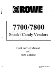
The bm transport (see figures 1-2 and 1-3) receives a bill as it Is inserted by the customer. The bin is
transported through the transport on a belt system, carefully evrsmArxMi and. if the bill is determined to
be valid, is delivered to the bin stacker.
Ifthe mil fells any ofthevalidation tests, the transport reverses and returns the bin to the customer. The
bin winhangin the transport inlet fara period of five seconds during which time the CCC windisplay a
message explaining the cause for the rejection.
Inlet Sensor
Mag Amp Cover
Transmlssrve
Sensor
Magnetic Head
(Opposite side of board)
Magnetic Amplifier Board
Figure 1-2. BUI Transport - Top View
1-2
gffflfltfffltf
Stfcflon 1: System Description
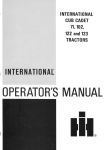
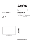
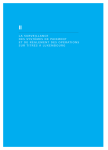
Anti-Cheat Lever
Interconnect Board
Assembly
Reflective Sensor
(Undwr Bond)
Motor
Legend Window LEDs
Inlet LED
4*\
Rgure 1-3. Bill Transport - Bottom View
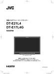
Bill Stacker
The bill stacker, shown in figure 1-4,
accepts the validated bills from the bill
transport and stacks them, one at a
time, in a removable slide-out box.
After the bill exits the transport and
falls into the stacker, a signal from the
control computer center energizes the
drive circuit inside the stacker and
relay K501 is pulled in. completing a
Stacker
Motor
circuit to the 115 VAC bin stacker
motor. The signal from the control
computer center is not long enough to
drive the stacker a full cycle, so a set
Cam Switch
S502
of contacts of K501 is used to hold in
Cam Switch
S501
the coil As the stacker leaves HOME
position, cam switch S501 closes,
followed closely by the switching of
cam
switch
S502.
Switch
S502
grounds a line back to the control
25238806
Rgure 1-4. Single Stacker
1-3
BC-1S0
computer, which prevents the acceptance ofbills and disables the machine ifthe stacker fails to complete
its cycle. About Vx second into the cycle. K501 drops out and the stacker motor operates through switch
/*^v
S501 only. As the stacker completes a cycle, cam switch S502 switches back and cam switch S501
opens, stopping the stacker motor. The stacker is now ready for another cycle.
Dispenser
The dispenser (see figure 1-5), contains the necessary components to handle the coins.
The com detector, consisting of an LED and a photo-transistor, detect the coins as they exit from the
hopper and fall into the upper coin chute. The upper coin chute directs the change to the lower coin
chute and then to the coin cup.
The drive for the hopper consists of an AC motor, which is also on the dispenser. This motor is controlled
by signals from the CCC.
You can access the rear of the dispenser assembly by removing the screw in the upper right comer,
grasping the dispenser at the top, and tilting the entire assembly forward on its lower pivots.
When you replace the dispenser, be sure that you tighten down the top screw securely. If this screw is
not tightened down, the entire dispenser assembly maytilt forward while loading, unloading, or removing
the hopper.
/t^\
Coin Dispenser
LED Assembly
Upper Coin Chute
Interconnect
Board
Dispenser
Motor
Coin Chute
Figure 1-5. Coin Dispenser (Rear View)
1-4
gggjffflftf
Section J: Syttwnt Description
Hopper
The biU changer contains one coin hopper (see figure 1-6), which mounts on the front surface of the
dispenser assembly and pivots forward from the bottom for loading, unloading, and removal (see table
1-2 for required hopper types and capacities).
The hopper transports coins to the coin detector and the upper coin chute by means of a chain conveyor,
which is driven from below by a sprocket. The chain follows a serpentine path, so that excess coins fall
back into the hopper ensuring only one coin per pin enters the coin counting area.
The chain picks up coins from the bottom of the hopper and carries them up to the top, where they fen
through the upper chain guide ring and Interrupt a light beam to a photo-detector, which is mounted on
the dispenser. The required number of coins for a desired change combination are counted in this
manner as the coins then fall through a closed chute to the coin cup.
An agitator, which is mounted on the drive shaft in each hopper, agitates the coin load to nummto coin
jams in the hopper and ensure efficient coin pick up.
To reduce jams and minimize the need for cleaning, the hopper has Teflon coated coin tracks.
Table 1-2. Machine Capabilities
Hopper Capacities
Hopper
Popular Coin Capacities
65027608
Small Coin
.705 to .955 inch diameter
Dimes
Nickels
Quarters
8,000
4.000
3.400
65027609
Quarters
SBA Dollars
.984 inch Tokens
3,200
2,200
3,000
Large coin/Token
.875 to 1.125 inch diameter
Machine Capacities
Bill Stacker
1,000 bills in biil box
Figure 1-6. Coin Hopper
Temporarily Out Of Service Lamp
This lamp is located on the door above the bill inlet area. It lights whenever the m^ftif is empty of
change or shutdown due to some mammrtlon. Pressthe FUNCTION key on the CCC to turn the OUT OF
SERVICE light offafter the machine has beenreloaded orif the malfunction has beenrepaired.
EMI Filter
The ElectroMagnetlc Interference (EMQ filter removes undesirable electrical noisefrom the Jnowmti^ power
line. The powertransformer supplies36 VAC and 22 VAC from whichthe rest of the system voltages are
derived.
2SB9SBD9
IS
BC-150
Power Control Center
AU power supply components and associated circuitry are located in this single subassembly for easy
diagnosis and repair. The power control center (see figure 1-7) is located below the bin stacker and
contains the dollars accepted counter. TEST VEND switches, power transformer, power supply circuit
board, circuit breakers, and ON-OFF switch.
»OWCM CONTMOL CCNTCH
65073501
On/Off Switch
Dollars Accepted Counter
Test Vend Switches
(Non-Functional)
Circuit
• 0 ;~01* i-*"^ Breakers
TF
Power Supply
Circuit Board
Power
Transformer
Figure 1-7. Power Control Center
DOLLARS ACCEPTED COUNTER
The dollars accepted counter registers the number of dollars accepted by the machine. The counter
increments once for each dollar (for example: A $5 bin win make the counter increment five times). This
counter is not resettable.
POWER SUPPLY
The ON-OFF switch controls power to the tn—inw»
A 7-amp circuit breaker is in the power line to the bin changer. The power transformer is protected by
a 2-amp circuit breaker in the primary winding. A 7-amp and a 5-amp circuit breaker protect the
secondary windings.
1-6
25238806
Section 7; System Description
r
The power supply circuit board rectifies and filters the 36 VAC and 22 VAC to provide 40 VDC. 30 VDC
(current limited) 12 VDC. 8 VDC. and 5 VDC to the rest ofthe system. It contains indicator LED's for the
40 VDC. 30 VDC. 12 VDC. and 5 VDC supplies.
This changer will shutdown for reasons other than being empty, specifically, if a fault or malfunction of
the machine occurs. When the changer shuts down, a message will appear on the display located on the
computer board. This message win aid the serviceman in quickly determining the malfunction or faulty
part (see Section 4, Troubleshooting).
TESTSWrrCHES
The TEST switches are non-functional in the BC-150.
POWER CONTROL RELAY
The power control relay switches the 40 VDC, 30 VDC. and 120 VAC. This relay is controlled by the CCC
and is energized under normal operating conditions. Under certpJn conditions the CCC de-energizes the
relay to disconnect the previously mentioned voltages from the rest of the system and shut down the
machine. In this condition, the +40 VDC LED on the power supply board will be OFFwhile the other three
remain ON.
Changer Control Computer
The Changer Control Computer (referred to as the "CCC" and shoum in figure 1-8) directs aU of the
operations ofthe biUchanger including both the validation and change dispensing functions. It contains
a microcomputer, which controls all of the major functions of the biU changer. It also contains the
following controls and displays:
G3D(55(5D
I
ty->ys.»'S'.'*yss :,
WW
10
553
0
5»sr~
1
Mm* i :m-MMw
P9
i
BUI. CHANGER
CONTROL COMPUTER
Rgure 1-S. Changer Control Computer (CCC)
e£mm*MT&OU6
1-7
BC-150
STATUS DISPLAY
The CCC containsmany programmingand sett-diagnostic featureswhich are describedto the paragraphs
that follow. AU messages are shown on a 16-charactervacuum fluorescent display. In some cases, the
message is short enough so that the word(s) can be spelled out: in other cases the word(s) are
abbreviated. The abbreviations are clear and logical and each message is described to Section 4 of this
manual
SERVICE AND CONTROL SWITCHES
The BC-150 Bfll Changer's service features and programiningoptions aj^ controlled by six switches. The
descriptions that follow are introductory: follow the detailed procedures and Instructions in Section 2 for
specific operating and programming information.
Prograrnrning/Normot
Selects either the NORMAL operating mode or the PROGRAMMING mode.
NORMAL POSITION
In the NORMAL mode position,the changer operatesin a normalmanner. The CCC monitors allsystems
for faults or customer input.
Three ofthe pushbutton switches provide unique features while the Twa^iitiy* is to the NORMAL mode.
^%
Function Pushbutton
Pressing the FUNCTION button makes the display access the coin control features when the COIN
CONTROL option is enabled (see Coin Control in this section for a detailed »»rlaTls>tlnT> of the COIN
CONTROL feature).
Value Pushbutton
Pressing the VALUE pushbuttonwin cause the display to showthe total dollar ammmt accepted since this
temporary audit value was cleared. Thus, ifyou clear this audit counter each +ftrw you load the hopper,
you can quickly spot check to see how much change has been paid out and thus determine whether or
not the biU changer needs to be loaded again.
Hopper Pushbutton
Pressing the HOPPER pushbutton win cause the display to show me last three denominations accepted.
The most recent denomination is displayed an the left side, the bin before that is displayed in the center,
and the earliest of the three bfll denominations is displayed on the right side.
PROGRAMMING POSITION
Setting the mode to PROGRAMMING position allows you to inspect and/or change the audit and setup
information. This information is displayed on the status display and is selected and changed by using
the five push buttons that are described in the following paragraphs.
J-8
25Z98806
Section 1: System Description
Function Pushbutton
Advances from the current set of options to the next set. The following list shows the sequence of options
that win be displayed as the FUNCTION pushbutton is pressed repeatedly.
1.
2.
3.
4.
TEMP COUNTERS
PERM COUNTERS
PROGRAMMING
HOP VAL
5. ACCEPT
6. PAYOUT
7. COIN CONTROL
If the FUNCTION pushbutton is pressed while COIN CONTROL is showing, the TEMP COUNTERS display
will reappear.
Hopper Pushbutton
In the PROGRAMMING mode, this pushbutton is only used to program a new access code.
Value Pushbutton
During the programming mode, this pushbutton is used to move between various values: i.e. the value
of coins in the hopper.
Up (a) And Down (v) Pushbuttons
Increment or decrement the displayed option value. Options that have only two possibilities, such as ON
and OFF, are toggled between the two options using either of these pushbuttons.
DENOMINATIONS ACCEPTED
The BC-150 can accept 1. 2, 5. 10. and 20 dollar bills of United States currency.
An of these
denominations can be selected in combination with other denominations.
COIN CONTROL
In other models ofRowe bill changers, an escrow bucket system is used. That system guarantees correct
change payout by counting the coins before a payout is required. The BC-150 is different because it pays
change directly from the hopper to the customer. This is necessaryto allow $1. $2. $5. $10. and $20 bills
to be changed and stiU keep the BC-150 *"naii
In order to prevent a customer from being short-changed, the BC-150 keeps track ofthe number ofcoins
left in the hopper. The BC-150 will shutdown when this number is not ennngh to guarantee a proper
payout.
The error message LOW HOPPER LEVEL indicates that the machine is out of service because there are
not enough coins left in the hopper for a payout of the highest allowed denomination.
25238806
1*9
BC-150
Coin Control Functions
The coin control system has four functions:
• Enabling the coin control option
• Setting the amount of money loaded Into the hopper
• Maintaining the amount of money in the hopper
• Keeping track of money paid out
Programming and operation of this system is fully described in Section 2.
1-10
25238806
Section 2: Installation & Programming
INSTALLATION
Installing the BC-150 BiU Changer requires no special instruction. For an types of installation, be sure
that a power source is convenient and that the changer is mounted leveL
BC-150 MOUNTING TECHNIQUES
The BC-150 can be mounted on the floor, a wall a shelf, a table, or on a slide base for a casino style
mount To Install the BC-150 with the slide mount, order Kit 27039701.
0*
NOTE:
For both security and safety reasons, Rowe strongly recommends that this bill
changer be securely anchored to the floor, table, shelf, or wail. Please check
the instructions that follow:
Mounting The BC-150 On A Wall
The fonowing inustrations and procedures should be used for wan mounting. For concrete or masonry
wall mounting, use lag screws and lead anchors. Forwood frame wall mounting, use lag screws attached
directly to the wall studs. If the wail is not flat, you may need to add spacer washers between the wail
and the mounting plate.
If changer is rigidlymounted to the wall, make the power input connection through rigid conduit into the
changer to meet U.L. requirements (see figure 2-1).
®r
NOTE:
if you are wail mounting the bin changer and drilling holes in it, be sure to
remove ail metal filings from inside the bill changer before putting the changer
into service.
Mounting The BC-150 On A Table Or Shelf
Use the four 1/2-lnch holes to the bottom ofthe BC-150 as a drlUing guide and drin four 3/8-to^ 1/2 inch
jf^-
holes. Secure the BC-150 to a sturdy table or shelf with four 3/8-to-l/2 inch bolts.
25238806
2-1
BC-150
AFTER REMOVING THE LINE
,— CONNECT THE POWER SUPPLYWIRES TO
THE INTERNALMACHINE WIRES PER
THE WIRING DIAGRAM IN SECTION 4
OFTHIS MANUAL USING STANDARD U.L
LISTED PRESSURE CABLE CONNECTERS
CORD ANDSTRAIN REUEF,
ENLARGE THE HOLE WITH A
7/8" D1A.CHASSIS PUNCH
JUNCTION BOX
__ (SUCH AS WIRE NUTS).
CONDUIT
CONNECTOR
CABINET BACK
EARTH GROUND
(GREEK/YELLOW OR GREEN WIRE)
Rgure 2-1. Instaifing 1/2 Inch Conduit
.'**•%
LEAD ANCHOR
NOTE:
BE SURE THAT THE LAO SCREWS USED
FOR ATTACHMENT ARE AT LEAST 30"
DUL, AND. FOR WOOD FRAME WALLS,
ARE ATTACHED DIRECTLY TO THE WALL
STUDS.
Mounting Orttil. Wood Ftmm WUI
LAO
SCREW
Mounting Drtsil.
twyWtfl
CONCRETE
WALL
*A\
Rgure 2-2. Attaching The BC-150 To A Wail
2-2
25238806
Section 2i Instotiotion od Pivytommtno
LOADING THE HOPPER
Review figures 2-3 and 2-4a before you begin,
1. Pull the hopper forward to its stop point.
2. Twist the top of a full coin bag one full turn. Grasp the
twisted top with one hand and hold the bottom of the bag
with the other. Invert the bag and Insert the top into the
mouth of the hopper.
3. Slowly release the twist as the bag empties. Avoid spilling
coins into the changer. Empty the bag by grasping it at the
bottom and shaking it to dislodge coins in folds of the bag.
Lift the hopper latch then push the hopper back into place.
4. Coin I.D. stickers are supplied with the machine to identify
the coin denominations in the hopper. Attach one of these
stickers to the hopper so that the coin denomination is
easily identified.
Figure 2-3 Loading The Hopper
0*
NOTE:
The hopper may be loaded with either SBA Dollar coins, quarters, or tokens
(nickels or dimes if the optional hopper Is being used). Make sure that the value
of coins loaded into the hopper agrees with the values programmed into the
computer during the HOPPER VALUE (HOP VAL) step of setup.
UNLOADING THE HOPPER
Refer to figwe 2-4 and unload the hopper as follows:
1. Swing the hopper stop rod out into Its operating position.
2. Pull the hopper forward to the stop point.
3. Placethe opening of the coin bag over the mouth of the hopper, wrapping the Up ofthe bag around
the handle. Grasp the bag and handle with one hand, tilt the hopper back, lift the hopper latch, and
slowly tip the hopper forward while holding the bag against the front of the hopper.
4. Hold the bag securely while you tip the hopper forward. Tap the hopper against the stop rod and
return it to the upright position. Repeat two or three more times to ensure that the hopper is
completely empty.
25238806
2-3
Hopper
Retainer
Hopper
Stop Rod
Figure 2-4A. Releasing The Hopper
Figure 2-4B. Unloading the Hopper
5. The hopper may also be removed from the mqni^f and inverted over the bag to empty. When
replacing the hopper, be sure that it is setting securely in the pivot brackets and snug against the
back plate. Put the stop rod back in its storage position.
OPERATIONAL INFORMATION
This bill changer uses several visual indicators and controls. The location ofthese controls and indicators
are as follows:
On-Off Switch
Located on the front surface of the power controlcenter
Circuit Breakers
Located on the front surface of the power control center (four total)
Dollars Accepted Counter
Located on the front of the power controlcenter
Test Switches
Located on the front surface of the power control center (non-functional)
voltage LED's
+5 VDC, +12 VDC, +30 VDC and +40 VDC are located on the edge of the
power supply board visible from the front of the power control center
Service/Programming
Located on the changer control computer
Switches
Status Display
2-4
y-a^
Located on the changer control computer
25238806
Section 2t Inst&Botion od PtoovonvninQ
Jp^
SETTING UP THE BC-150
These steps should be followed to setup the BC-150 to your requirements. If you do not follow these
steps, the BC-150 will remain all or partially programmed to the factory settings.
This procedure follows the "beglnnlng-to-end" setup sequence. You should follow this procedure and use
it until you are familiar with the eight groups of setup options. Once you are familiar with these options,
you can easily skip over the options that you do not wish to change or display.
Key Information
In the step-by-step procedure that follows, key setup information follows many of the numbered steps.
This information will be very helpful, but it can be skipped. Key information paragraphs are indicated
by a small o-i to the left of the key paragraph.
Turning The Power On
1. Turn the power switch ON. Three of the four voltage LED's on the power control center should now
be ON. The 440 VDC LED will be OFF. The OUT OF SERVICE light will be lit
2. The message: BC-150 will briefly appear on the display.
3. The message: VERSION XX will briefly appear on the display. XX is the version number and should
match the version number on the EPROM label, which is visible through the cover of the CCC.
4. The message: CHECKSUM XXXX will briefly appear on the display.
checksum. The Right-most two digits must be 00.
XXXX is the 16-bit EPROM
JfPN
5. Next, the RAM TEST PASSED (or FAILED) message will briefly display. If the word FAILED appears,
the changer will remain In the OUT OF SERVICE mode.
6. When the RAM TEST PASSEDmessage disappears, the 'walking" dash will appear. The 440 VDC LED
will light and the OUT OF SERVICE light will turn OFF.
Switching To The Programming Mode
Steps 1 and 2 display "audit" information. These two steps are the only displays that will appear if an
access code (other than OOOO) is used and the operator has not yet entered the correct access code.
To enter the PROGRAMMING mode:
1. Move the slide switch on the CCC to the PROGRAMMING mode position.
The display win change from the 'walking dash" to TEMP COUNTERS. This function will allowyou
to view and reset the quantity of each denomination that has been accepted since the numbers were
last reset to 0. The denominations are displayed In the following order $1. $2. $5, $10, and $20 as
the VALUE pushbutton is pressed. The last item displayed is the AMOUNT $XXX-XX — This is the
dollar amount accepted since the last time it was reset to zero. Push VALUE againto wrap around
to the $1 displayed quantity.
The counts previously listed can be reset Individually by pressing both of the arrow pushbuttons
(A and V) at the same time while that count is displayed. You can reset all of the counts and the
amount accepted at once by pressing the HOPPER and A pushbuttons at the same time while any one
j0^\
of the counters is being displayed. At this time, the message TOTALS CLEARED will be displayed
briefly to indicate that all of the numbers have been reset to zero.
25238806
2-5
BC-150
2. Press the FUNCTION pushbutton and the display will change to PERM COUNTERS.
/*^|l
o-i
This display indicates the quantity ofeach denomination that has been accepted since the Tnnntnw^
was built. To use these for periodic audits, you must know the starting count and current count
and subtract These quantities cannot be reset Press the VALUE pushbutton, to display the
denomination and quantity of each denomination accepted.
3. Press the FUNCTION pushbutton and the display will change to PROGRAMMING —.
This is the display for entering the four digit access code. Initially, the BC-150 access code is set to
0000. This is a special access code in that no further entries are required to reach the set up
functions described below-simplv pressthefunction buttonto advance to the aetiip functions Ifany
other code has been entered into the computer, however, access to set up functions will be denied
unless the correct code is entered.
IF NO ACCESS CODE HAS BEEN ESTABLISHED
4. Go directly to Step 5.
IF AN ACCESS CODE HAS BEEN ESTABLISHED
A. Thelefttwo digits ofthe access code will be blinking (thisis the BC-150's way ofindicting which
information will be changed ifyou makea change). Press the a or v pushbutton to change the
left two digits of the four digit access code.
o* The a and the v pushbuttons will allow the numbers 00 through 99 to appear in each of the
two halves of the four digit access code.
B. When the display shows the correct two left-hand digits of the access code, press the VALUE
pushbutton.
C. The right two digits of the access code willbe blinking at this time. Press the a or v pushbutton
until the right two digits of the four digit access code are correct.
D. When the display shows the correct two right-hand digits of the access code, press the VALUE
pushbutton to advance to the setup functions that follow (if an incorrect code is entered, the
display will show: LEVEL 0 ACCESS: then, it will return to the PROGRAMMING — display. A
correctly entered code will display LEVEL 1 ACCESS):
TO PROGRAM A DIFFERENTACCESS CODE
A. If me access crcde is presently 0000, go diratfy to
B. If a non-zero access code is currently in the computer, you must first enterthat code as described
in the previous paragraph. Then, using the FUNCTION pushbutton advance through each of the
setup and audit functions until PROGRAMMING — is again shown on the display.
C. Enter the desired access code using the (A), (V), and value pushbuttons as described in Step C
and Step D in the previous procedure, but do not press the VALUE pushbutton a second time.
With the desired four-digit code showing on the display, press and hold the HOPPER pushbutton
for about three seconds until the message NEW CODE STORED appears. The new code has now
been stored in the computer's memory and will be the required access code the next time the
programming mode is entered.
2-6
25238806
•^^k
Section Z Instaikrtton od Programming
5. Press the FUNCTION pushbutton and the display will change to HOP VAL
o-i The HOPperVALue option allows you to select the denomination to be dispensed from the hopper
(see table 2-3 for the list of denominations). If the hopper value is set to dashes (- -), the hopper
will not dispense any coins at any time.
The computer must know the value of coins used for one important reason. The BC-150 supports
a "correct payout feature" — the computer simply will not allow you to program a payout that does
not total the amtnvn* taken in unless vou set the hopper value to tokens. The correct payout feature
prevents pipgrammlng errors and the resulting over or under-payment
6. The left two dashes will be blinking. Press the VALUE pushbutton to step through the possible hopper
denominations. Stop when the correct hopper value Is displayed.
Use the coin value stickers supplied in the accessories bag to label the hopper as a reminder of which
coins are to be loaded In each hopper.
Table 2-3. BC-150 Hopper
Value Codes
ISymboll
:SS::-s*:-.-v--. .__
5
Nickel
10
Dime
25
Quarter
$1C
•
Dollar (SBA)
T1
Token Type 1
T2
Token Type 2
T3
Token Type 3
7. Press the FUNCTION pushbutton and the display will change to ACCEPT $1 YES (or NO).
8. Press either the a or v pushbutton to select (turn ON) or deselect (turn OFF) each denomination.
Press VALUE to step through the list of denominations that can be accepted (see table 2-4 for the list
ofdenominations).
25230000
2-7
BC-150
Table 2-4. BC-150
Acceptance
Display
Symbol
Money
Type
$1
One Dollar Bill
$2
Two Dollar Bill
$5
Five Dollar Bill
$10
Ten Dollar Bill
$20
Twenty Dollar Bill
Select only the denominations that you want to have the BC-150 accept by using the a or the v
pushbutton.
9. After you have programmed the denominations you wish to accept, press the FUNCTION pushbutton
to move on to the PAYOUT function.
10. The display will show:
XXX PAY - -. The XXX will the lowest bill denomination set to ON.
The right two digits will be blinking.
11. Press the a or the v pushbutton to increase or decrease the coin count to be paid from the hopper.
Once you have the count set as you want for the displayed denomination, press the VALUE
pushbutton to advance to the next denomination. If you have made an error and the payout value
is not equal to the displayed denomination, the display will briefly show INCORRECT PAYOUT and
then return to the same denomination - refusing to advance. This is true unless you have set the
hopper value to one ofthe token values. You will not be able to leave this display, even if you put the
PROGRAMMING/NORMAL switch in the NORMAL position.
When the VALUE pushbutton is pressed and held for more than two seconds, the display will show
XXX PAYS
. The XXX represents the current denomination. The
will show TOKENS if
tokens are loaded into the hopper or if only coins are used, the display will show the total dollar value
of the coins to be paid out.
12. After you have programmed the payout for all of the denominations being accepted, press the
FUNCTION pushbutton to move on to the COIN CONTROL function.
13. The display will show: COIN CONTROL ON (or OFF)
14. Press either the A or the V pushbuttons to turn the COIN CONTROL feature ON or OFF.
2-8
25238806
Section 2: inUBioflon ad Pruyjunmdnj
J^y
A
WARNING:
If the COIN CONTROL option is turned OFF, there is a possibility that a customer
could be short-changed if the hopper goes empty.
Once you have set the COIN CONTROL option, press the FUNCTION pushbutton to advance to the
beginning of the entire programming sequence (TEMP COUNTERS will show on the display) and you
may review your setup by stepping through each function again.
To return the bill changer to normal operation, move the slide switch from the PROGRAMMING to the
NORMAL position. The display will show the "walking dash" again.
USING THE COIN CONTROL SYSTEM
Keeping track of money paid out is automatically done by the bill changer control computer. When the
remaining amount ofmoney gets too low, the bill changer will shut down with the error message: LOW
HOPPER LEVEL
Telling the BC-150 how much money is loaded in the hopper and maintaining this amount is done by the
FUNCTION, A, and V pushbuttons in the NORMAL operating mode.
Pressing the FUNCTION pushbutton, while in the NORMAL mode, with the COIN CONTROL option turned
on, will cause the display to show the amount of money or number of tokens remaining in the hopper.
If coins are being dispensed, the display will show $XX LEFT, where XX Is the amount in dollars left in
the hopper. If tokens are feeing dispensed, me display will show: XXX TOKENS LEFT, where XXX is the
number of tokens remaining in the hopper. At this display, the dollar amount or the number of tokens
can be reset to zero by pressing the A and V pushbuttons at the same time.
Press the FUNCTION pushbutton a second time to advance to the next COIN CONTROL mode. The display
will show: ADDING 0. Pushing the A pushbutton will add either $50 or 50 tokens to the hopper total
Each time the A pushbutton is pressed, another $50 or 50 tokens is added to the hopper total The V
pushbutton will subtract $50 or 50 tokens. Use the A and/or V pushbuttons, as described, to let the
computer know how many coins or tokens you have added to the hopper.
pushbutton to return to the NORMAL mode.
Press the FUNCTION
If the amount of money or number of tokens entered is not adequate to ensure payout of the largest
denomination dispensed (plus 25 extra coins), the bill changer will shut down immediatelywith the error
message: LOWHOPPER LEVEL When this message Is displayed, pressing the FUNCTION/ERROR CLEAR
pushbutton will display the amount of money or the number of tokens left in the hopper. Pressing the
FUNCTION pushbutton again will allow you to add more money or tokens to the hoppertotal as described
above.
The bill changer control computer will not let the bill changer go into NORMAL operation until the dollar
amount or the number oftokens is adequate to payout the largest denomination dispensed (phis 25 extra
coins).
25238806
2-9
BC-150
When the COIN CONTROL option is turned OFF, the computer does not keep track ofthe number of coins
or tokens that are left in the hopper. The bill changer will shut down with the error message: SHORT
XX COINS ifit cannot payout the correct number of coins. The XX indicates the number of coins that the
last customer was shorted.
SELF DIAGNOSTICS
Diagnostic Check
The self diagnostic features of the BC-150 are centered around the 16-character status display. The
message displayed may be on aU the time (STEADY STATUS MESSAGE), or they may blink on and off
(FLASHING FAULT MESSAGE).
Fault Message Check
1. Remove the hopper from the machine. Block the coin detector on the dispenser with an opaque
object—a piece of steel, for example. The machinewingo out ofservice. The status display will flash
the message CK LCOIN DETCTR andthe TEMPORARILY OUT OF SERVICE light on the door will light
2. Restore the machine to service by removing the object that is blocking the detectorand pressing the
FUNCTION pushbutton.
3. The CCC will remove the fault message and the mantii™* will return to service.
4. Replace the hopper.
For detailed explanationsof the various fault messages, refer to Section 4, Troubleshooting.
Status Messages
When a message is on the status display and it is not flashing, either a fault or malfunction occurred
that was not serious enough to cause a shutdown or the message is a guide to solving bill acceptance
problems.
BILLACCEPTANCE MESSAGES
A bin may be rejected for a number of reasons. The status displaywill tnq^t* the reason why a bill
failed to be accepted. A number of cellsequence rejectsand binvalidation rejects exist These messages
will be displayed for approximately five seconds before they are erased by the walking dash. Formore
information on reject messages, refer to Section 4, Troubleshooting,
TRANSPORT SELF-CLEAR CHECK
If a bill becomes Jammed in the transport, the BC-150 automatically tries to clear it out To check out
this feature:
1. Insert bill into transport upside down.
The bill will reject and status display will show
REJECT-NO MAG.
2. Hold the bill in the transport Do not uncover the VI cell. Wait five seconds for the transport to start
to cycle reverse-fbrward-reverse-forward-reverse. The transport will do this three times if VI cell is
kept covered. During the self-clear operation, the status display win show the message PURGING
ACCEPTOR.
2-10
25238806
-^^\
Sections InstaBation ad Programming
f^
3. The motor will stop and the status message will change to CK TRANSPORT VI (If the VI cell is
uncovered any time during the selfclear cycle, the machine will automatically go back into operation).
4. Restore machine to service by removing the bill.
ACCEPTANCE CHECK
To aid in checking acceptance, set the hopper value to Tl, T2. orT3. Set all pay counts to zero. This will
allow checking out the validation portion of the system without having the hopper motor run.
1. Make certain that the bill is programmed to be accepted.
2. Insert a dollar bill upside down. The bill should reject and the display should show REJECT-NO MAG.
3. Insert the dollar bill correct side up, but backwards. The bill should reject and the display should
show a message REJECT-BILL (B).
Now insert the dollar correctly. It should accept the stacker should operate (since all payouts are set to
zero, the hopper motor should not operate). The dollar accepted counter should also advance one count
Also, as the bill moves through the bill acceptor, check to ensure that the following messages are shown
on the status display:
1. VALIDATING will appear as the bill is inserted and while the transport is running.
2. $1 PAYS 000 will appear when the bill is validated and stacked.
3. If bills in good condition are rejected frequently, note the reject message on the status display and
refer to Section 4 for troubleshooting information.
4. If the machine is set up to accept other bills, the previous checks should also be performed with all
other denominations.
When other denominations are accepted, the display will show $XX PAYS 000where the XX represents
the denomination.
MISCELLANEOUS
The BC-150 was designed to be simple and easy to troubleshoot Pleasetake time to study the operation
of the machine and to study the erpianatinn^ of the various status messages
The following is a list ofincidental characteristics that may be ofinterest to the operator and service ™m
1. The +5VDC voltage from the power supply does not control the CCC board. It Is used to provide
voltage to LED's (dispenser, transport, and OUT OF SERVICE light). The computer board is powered
primarily by the +8 VDC voltage from the power supply. It has Its own +5 VDC regulator.
25230006
2-11
BC-150
2. If power is disrupted during a dispense cycle, the machine will immediately reset upon power turn
on. The customer will most likely be short-changed.
3. Blocking the coin photo detectorwith your fingers, orwith foreign objectsduring replenish cyclemay
result in Wrong COUntS. Ifthe detector is, hlnrkeri tnnInng, the machinewfflshut Hnmm urtth a flashing
errormessage indicating that the detector was blocked. Ifthe wrong count is entered the display may
show a flashing message EXTRA COIN. Either condition will put the manhi™ in a shutdown mode.
4. Alwaysturn powerOFF when removing circuitboards. Avoid touchingme connectors when handling
these assemblies.
A
WARNING:
When the machine is turned on, there Is 120VAC voltage on the computer
control board. If, for any reason mis board is plugged in without Ms cover on.
BE CAREFUL!
2-12
25238806
"**%
Section 3: Routine Service
INTRODUCTION
In order to maintain control over money used for change dispensing, each changer should be charged
with a predetermined amount of cash. The inventory should be checked periodically as a precaution
against marfimctinn and theft. Inventory control is most easily accomplished by using the replacement
method of servicing. Using this method, all bills and coins are removed by the route man and the empty
hopper is refilled with a predetermined amount of change. The money removed is returned and all cash
is counted against the charged inventory. Any discrepancy is easily detected at this time (for more
information, see Low Hopper Level in the Troubleshooting paragraphs of Section 4).
Service frequency on the changer is directly related to the Inventory ofchange maintained and customer
usage. Check changer usage dally and schedule service as required.
REMOVING A JAMMED BILL FROM THE BIU ACCEPTOR
Jammed bills can be easily removed in the following manner
1. Unlock and open the door. Turn the power OFF.
{
2. Slide the bill acceptor out until it stops.
3. Remove the Jammed object from the acceptor.
BILL JAMMING CHECK LIST
If bills Jam frequently, perform the following checks and corrective procedures (see figure 3-1):
1. Make sure that all belts stay centered on all rollers when the transports running In either the
forward or the reverse direction.
2. Check to see that both timing belts are snug (not too loose or too tight).
3. Make sure that the rubber drive rollers are not loose or worn.
4. Exit flipper must work freely.
5. Be sure that the Nylon idler roller rotates freely and moves up and down freely in its slot. The
retaining springs must also slide without bind in the guide slots and exert adequate force on the
Idler roller.
6. Bottom trackbill surfaces must be free ofdirt,moisture, burrs, projections, rough spots, etc, which
might drag or hang up on the surface of bilL
7. The magnetic head must have a bevelled edge on both front and back to keep both bin edgesfrom
becoming caught to forward or reverse.
8. Nylon rollers on the magnetic head assembly must rotate freely.
No dirt, moisture, burrs,
projections, or rough spots can be on the magnetic heads or magnetic head holder.
•3830000
3—1
BC-150
Drive Roller
Timing Bert
Drive Roller
Exit Flipper
Drive Roller
Drive Roller
Rgure 3-1. Transport Check Points
CLEANING THE HOPPER
COIN PATH
The coin tracks are Teflon coated to minimize dirt
build-up. It may still be necessary to clean them
at regular intervals, as dictated by the number of
vends and the environment, to prevent dirt
accuDiulation in the coin path.
Clean Top And
Angular Coin
Path Surfaces,
Especially At
Guide Edges,
As Shown.
Failure to keep the coin path clean may result to
coins sliding out ofthe track. Indicating an empty
condition even though the hopper contains
sufficient coins. Clean the hopper as follows:
1. itoovemehopperfiOTthebm
place It on a working surface.
Rc^ro 3-2. Cleonlng Iho Hcijpef Ccln Path
2. Using the Nylon hopper gleaning hruah mippHeHurtth e*oh nwrlriiw, nrprum aTl <foffirrrrn the angularsides and flat surfaces ofthe serpentine coin path as shown injiaure 3-2.
3-2
Section 3: Routine Service
jp^.
3. Install the hopper In the bill changer and run a few bills through to check for proper hopper
operation.
CAUTION:
A
Do not use detergents to clean the hopper. The hopper has been factory
lubricated and detergent cleaners destroy this lubrication.
TEST PROCEDURES
Transport Motor Speed Check
The BC-150 transport motor speed and direction are computer controlled. No adjustments can be made,
however the encoder on the back of the motor can be checked. The computer detects pulses from this
encoder for speed control.
1. Remove the transport from the machine, but keep it plugged in and keep the bill changer power ON.
2.
Turn the transport over and connect the Ctommon lead of a voltmeter to P701. Pin 10. Connect the
other lead to P701. Pin 9. Turn the transport motor drive shaft very slowly by hand. The meter
should alternately read voltages below 0.7 VDC then above 3.8 VDC.
3. One rotation of the motor drive shaft will produce 100 pulses.
Dispenser Coin Detector Check
1. Remove the hopper from the machine.
2. Turn the bill changer power on. Verify that the Red LED is lit and is shining on the hole In the upper
coin chute assembly (The dispenser hold-down screw may be removed and the dispenser pulled
forward to allow viewing).
3. Connect the common lead of a voltmeter to P3 Pin 4 on the CCC. Connect the other lead from the
voltmeter to P4 Pin 1. A voltage reading between 2.8 VDC and 5.1 VDC should be observed.
4. Block the light path in the detector with an opaque object. The voltage reading should drop below
0.7 VDC. The CCC should shut-down with the error message: CK L COIN DETCTR.
5. Remove the object blocking the coin detector, then push the FUNCTION button to clear the error.
25238806
3-3
BC-150
Testing BC-150 Transport Photocells
The transport photocells are automatically checked each time the transport is turned on. Each photocell
and light combination goes through a short test and brightness adjustment process. This process
continues as long as the transport receives power. No adjustments <w be made; however, a bad
photocell can be detected with a voltmeter. All measurements are made with the Common lead of the
voltmeter connected to P701. Pto 10 on the transport (the voltmeter should have a minimum impedance
of 10 megohms).
Photocell Troubleshooting Chart
Pbotoceti
VI - Transport inlet
Action
No Action - Leave the inlet open
Vottago Expected
P701, Pin 7 should be between 0.2 VDC
and 1.9 VDC
Blockthe light path by inserting
P701, Pin 7 should increase at least 0.5
paper or a bill into the transport
volts from the reading taken with the inlet
open. The transport motor should start
running forward. Hold the bill in place
until you finish the reading, then remove
the bill and let the transport finish cycling.
opening
VF - Ripper Ceil
No Action - Leave ffipper in rest
P701, Pin 5 should be less than 1.0 VDC
position
Block the light path with the
flipper
VT - Trcrnsrnissive Ceil
P701, Pin 5 should be greater than 2.8
VDC
No Action - Leave the light path
P701, Pin 4 should be 0.75 VDC to
open
1.25 VDC
Block the light path by inserting
P701, Pin 4 should increase by at least
0.75 VDC from the reading taken with the
light path open
paper or a bill between the
transmissive cell and the transmissive/reflective LED in the
middle of the transport
VR - Reflective Cell
No Action - Leave the light path
P701. Pin 6 should be between 0.8 VDC
open
and 2.0 VDC
Insert a white piece of paper
P701, Pin 6 should increase by at least
0.25 VDC from the reading taken without
white paper inserted.
between the transmissive cell and
the transmissive/reflective cell
Z-4
jPffflPffli*
Section J.* Routine Senrice
ADJUSTMENTS
Hopper Chain Adjustment
1. Loosen the three screws at the top back ofthe hopper, which will allow the black plastic upper chain
guide ring to move diagonally upwards.
2. Pull the upper chain guide ring up as shown in figure 3-4. while you rotate the drive pin clockwise
until the slack is removed from the chain but no binding is evident.
3. Tighten the three screws making sure the lower screw is tightened last. If a torque wrench is
available, adjust the chain so that the torque input at the drive pto is one to four inch pounds.
j0f*\
Rgure 3-4. Hopper Chain Adjustment
r
25238806
3*
BC-150
Bill Stacker
A stacker cycle will start each time a bill is accepted. Adjust the bill stacker switch as follows:
1. Remove the bill stacker from the bill changer.
2. Hold the motor brake to (disengaged) and
manually rotate the motor shaft until the
Adjustment Screw
stacker is one-half cycle away from HOME
position (the stacker push plate is at its outer
most extended position). The cam and cam
Spring
9/32 (.281) Rod
(7.14 mm)
switches should be accessible from below and
the narrow lobe ofthe cam should be pointed
at the switches as shown in figure 3-5.
3. Adjust the cam switches by loosening the
adjustment screw and rotating the switch
bracket until a .281 diameter rod bottoms
against the switch as shown (an ordinary
wooden lead pencil is approximately this
diameter).
Switch Bracket
4. Tighten the adjustment screw and re-install
the stacker in the changer.
5. Install the stacker, turn on the power, and the
stacker win return to its HOME position
automatically.
Rgure 3-5. Stacker Switch Adjustment
Timing Belt Tension
Refer to figure 3-6 for this adjustment procedure.
1. Turn transport upside down.
2. Loosenthe two screws (A) holding the belttension adjustment levers (B) on both sides ofthe
bill acceptor transport.
3. Make sure that the adjustment levers, adjusting roller and shaft move freely.
4. The timing belts should be adjustedtight enoughthatthey do not come offthe pulleys, but not
so tight that they put excessive load onthe transport/ This tension is achieved by adjusting the
belts to the point that the slack is taken up. Ifamore precise adjustmentis desired perform the
following step:
A. Apply 75 grams ofperpendicular force to both belt tension adjustment levers at the
sametime andthen tighten all fourscrews.
Apply 75 grams of force at this
point in the direction shown
'-s\
3-6
B
A
Figure 3-6.TimingBelt Adjustment
25238806
Section 4: Troubleshooting
INTRODUCTION
The BC-150 incorporates major assemblies and components as field replaceable plug-in units. There are
several on-board diagnostic indicators on these assemblies. The lnfonnatlon in this section takes full
advantage of this design by isolating possible xnalnmctions to one or more of these basic plug-in units.
This method saves time and requires little training in electronics.
The most significant troubleshooting aids for the BC-150 are the on-board LED's and the status display
on the Changer Control Computer (CCC).
POWER UP DIAGNOSTICS
As power is applied to the BC-150. a series of power up checks are performed by the CCC before the
machine is put into service. The 16 character alphanumeric status display on the CCC is the primary
diagnostic indicator. A secondary Indicator is provided by the green reflectrve/transmissrve LED in the
bill transport
The following chart describes the power up sequence along with what is shown on the status display.
The condition of the secondary indicator is also described.
Action -Turn the Power Switch to the ON position.
Power-Up Sequence
Sequence I
Status Display
.
Transport LED
1
Display shows: BC-150
LED flickers ON briefly
2
Display shows: VERSION XX
LED remains OFF
3
Display shows: CHECKSUM-XXOO
LED Turns ON for about Vz
second then turns OFF
4
Display shows: RAM TEST PASSED
LED Turns ON for about %
second then turns OFF
5
Display shows: RAM TEST PASSED
LED Turns ON for about Vfe
second then turns OFF
6
Display clears then a walking dash appears
LED Turns back ON slowly
-rnr iU'imiii ...jiulm,,
m
,,uai—13
The steps that follow describe the power-up sequence in detaiL
25238806
4-1
BC-150
Sequence Descriptions
•^^Ik
1. Power is turned on.
2. During this time the CCC is performing internal tests on it self. Several things may indicate trouble.
If the LED In the transport comes ON and stays ON and the display stays blank, there is a problem
with the microprocessor on the CCC board. If the LED in the transport continues with the power
up sequence but the status display stays blank, there is a problem with the display and it associated
circuits on the changer control computer board.
The XX on the display represents a softwareversion number that willbe displayed there.
Example:Version 1.0 softwarewillbe displayed as VERSION 10. The version number displayedwill
match the version number visible through the hole in the lowerleft corner of the CCC assembly.
3. During this time, the CCC is checking the integrity of its own program. The checksum displayed
must end with two zeros. If the checksum does not add up right, the machine will not continue with
the power up sequence. The display will be left showing the Incorrect checksum and the LEDin the
transport will stay ON.
4. During this time, the CCC is testing the Random Access Memory (RAM). If the RAM test does not
pass, the message on the status display will say RAMTEST FAILED. The machine will not continue
the power up sequence and the LED in the transport will remain ON.
5. During this time, the CCC is checking the machine configuration. If the configuration is the game
as when the machine was turned OFF, it will go to normal standby operation. If the configuration
changed due to low batteryvoltage or some other reason efiecrttog me RAM,the display wm show SET
UP REQUIRED. In this case, the maehine will require reprogramming.
6. This is the stand by condition. A dash walks back and forth across the status display and the LED
in the transport Is ON.
MACHINE STATUS
The status ofthe machine is displayed on the status display during all phases of operation. The following
section will describe the status messages displayed.
Standby Mode
The STANDBY mode is the normal, waiting to accept money, mode. AH four voltage LED'S on the power
control center are lit The LED on the dispenser is lit All LED'S in the transport are lit There is a dash
walking back and forth across the display. The hopper motor, stacker, and transport motors are OFF.
The OUT OF SERVICE lamp is OFF.
In the STANDBY mode, the HOPPER and VALUE keys on the CCC have special functions. When the
VALUE key is pressed, the status display will show AMOUNT $XX-XX. where XX-XX is the amount of
money that has been accepted since this amount was last cleared. When the HOPPER key is pressed,
the status display win show LAST XXX XXX XXX. where the XXX indicates the last three denominations
paid out The denomination on the left is the most recent, the denomination in the center paid before the
one on the left and the denomination on the right paid before the center denomination.
4-2
25238806
•^
Section 4: Troubteshoottog
Accept And Payout Modes
During normal operation, the display will reflect each state the machine goes through as it happens.
When a bill Is moving in the transport, the message VALIDATING will appear. Aftervalidation, during the
stack and vend cycles, the display will show the message XX PAYS -. The XX indicates the denomination
just accepted and the — represents the number of coins from the hopper needed to be paid out. During
payout, as coins pass through the detector, the displayed com count will be reduced until it reaches zero.
The machine will then return to the STANDBY mode.
Reject Mode
While the machine is validating a biU. several things may cause the bill to be rejected. When a bill is
rejected, the transport will reverse returning the bill and the status display will show a reason for the
reject. This reject message will stay on the display for about five seconds, then the walking dash will
erase it. A list of reject codes follows with an explanation for each and some hints on where to look for
trouble if the same reject message continues to appear.
25238806
4*3
Index to Error Messages
And Troubleshooting Charts
-
+5 VDC Failure, +5 VDC LED Out
4-40
BUI Changer Gives Erratic Payout For Bills
(No Error Messages)
4-38
Bill Changer Steals Bills
4-37
Bill Stacker Problems
4-39
Bill Transport Fails To Run In One Or Both Directions
4-36
CK L COIN DETCTR
4-24
CK STACKER
4-32
CK TRANSPORT MAG
4-19
CKTRANSPORTVF
4-20
CKTRANSPORT VI
4-20
CK TRANSPORT VR
4-21
CK TRANSPORT VT
4-20
CK TRANSPORT XX
4-21
ERROR ??
4-34
EXTRA COIN-L HOP
4-28
Hopper Motor Fails To Run
4-35
L DETCTR ON LONG
4-26
L HOPPER EMPTY
4-30
LOW HOPPER LEVEL
4-23
/^Sv
4*
25238806
REJECT-ACCPT OFF
4-18
REJECT-BILL (B)
4-16
REJECT-BILL (C)
4-16
REJECT-BILL (D)
4-16
REJECT-BILL (E)
4-17
REJECT-BILL (F)
4-17
REJECT-BILL (G)
4-17
REJECT-LATE VF
4-13
REJECT-LONG VF
4-10
REJECT-LONG VI
4-9
REJECT-LONG VT
4-10
REJECT-LOST TACH
4-15
REJECT-NO MAG
4-12
REJECT-SHORT VF
4-7
REJECT-SHORT VI
4-6
REJECT-SPEED
4-14
REJECT-TIMEOUT
4-8
REJECT-VF OPEN
4-15
REJECT-VI AGAIN
4-7
REJECT-VT AGAIN
4-11
SHORT XX COINS
4-22
J^1-
25238806
4*8
BC-150
VALIDATION REJECTS
Cell Sequence Rejects
REJECT-SHORT VI
Symptom:
The inlet cell was covered for too short of a time.
This is a reject message.
The bill was rejected because the VI cell was not covered long enough. The bill may have been torn on
the right side, torn, or folded over at the trailing edge of the bin. If bills are rejected frequently with this
code, the VI cell may be giving an intermittent signal.
This message may also appear ifVT is giving an mtermittent signal.
Corrective Action:
1. Check the VI cell for proper switching.
2. If the cell is OK. check the wiring from the VI cell to the CCC for a possible short to the chassis.
3. Check the VT cell for proper operation (see Section 3. Testing BC-150 Transport Photocells).
4. Check the wiring from the VT cell to the CCC for possible shorts or opens.
5. The +5 VDC supply to the LED's may be below 4.5 VDC: check the voltage. If It is low. replace
regulator VR801 on the power control center (see the components list for the power supply circuit
board).
6. If all of preceding checks are OK, replace the CCC.
If the bill is left in the transport for five seconds, the machine will go into SELF-CLEAR.
4*6
25238806
Section* Troubleshooting
REJECT-SHORT VF
Symptom:
Flipper cell covered for too short a time.
This is a reject message.
The bill was rejected because the flipper cell was uncovered too soon and the CCC recognized this as a
non-valid validation sequence. If bills are rejected frequently with this message:
Corrective Action:
1. Check for small pieces of paper or other foreign objects in the track.
2. The flipper may be binding or hanging-up on the back rollers. Check for flash orburrs on the flipper
and back rollers.
3. The flipper cell may be giving an mtermittent signal. Check the cell for proper switching. If the cell
is OK. check the wiring from the transport to the CCC for a possible ground to the chassis.
4. If all of the preceding checks are OK. replace the CCC.
If the bill Is left in the transport for five seconds, the machine will go into SELF-CLEAR.
REJECT-VI AGAIN
Symptom:
A second bill was inserted while validating the first biU.
This is a reject message.
A bill was rejected because the VI cell was covered while the changer was in the process of validating a
bill.
Wait until the changer completes the cycle before you insert the next bin.
If bills are rejected frequently with this code, the VI cell may be giving an intermittent signal
Corrective Action:
1. Check the VI cen for proper switching. If the ceU is OK, check the wiring from the VI ceU to the CCC
for an mtermittent open connection.
j0^\
2. If both of the preceding checks are OK, replace the CCC.
If the biU is left in the transport for five seconds, the bin changer win go into SELF-CLEAR.
25238806
4-7
BC-150
REJECT-TIMEOUT
Symptom:
Inlet cell was never uncovered.
This is a reject message.
The bin was rejected because the VI cen never uncovered. The CCC recognized this as a non-valid
validation sequence. Take the fonowing corrective action ifbills are rejected frequently with this code.
Corrective Action:
1. Check for small pieces of paper or other foreign objects in the track.
2. The VI cen may be giving an intermittent signal Check the VI cen for proper switching.
3. If the cell Is OK. check the wiring from the VI cell to the CCC for a possible short to the chassis.
4. The +5VDC supply to the LED's may be low; check the voltage. If it is low. replace the regulator on
the power supply board, which is inside the power control center.
5. If an of the preceding checks are OK. replace the CCC.
If a biUis left in the transport for five seconds, the bin changer wul go into SELF-CLEAR.
•^^Sv
4*8
25238806
Section* Troubleshooting
REJECT-LONG VI
Symptom:
The inlet cell was covered for too long a time.
This is a reject message.
The biU was rejected because the VF or VT cell was covered too soon, or the VI cell was covered too long.
The CCC recognized this as a non-valid validation sequence.
If bills are rejected frequently with this code, take the following collective action:
Corrective Action:
1. Check for small pieces of paper or other foreign objects in the track.
2. The VF flipper may be binding or hanglng-up on back rollers.
3. Check for flash or burrs on flipper and back rotters.
4. The VF ceU may be giving an intermittent signal. Check the ceU for proper switching. Ifthecenis
OK. check the wiring from the VF ceUto the CCC for a possible ground to the chassis.
5. The VT cell may be giving an incorrect or intermittent signal. Check the wires for broken or loose
connections.
6. The voltage measured across the VT cell should be between .75 VDC and 1.25 VDC.
7. If an of preceding checks are OK. replace the CCC.
If a bin is left in the transport for five seconds, the bin changer win go into SELF-CLEAR.
25238806
4-9
BC-150
REJECT-LONG VT
Symptom:
The transmissive cell covered for too long a time.
This is a reject message.
A bin was rejected because the VT cell was covered too long.
A bin may have hung-up or Jammed in the transport
If bills are rejected frequently with this message, take the fonowing corrective action:
Corrective Action:
1. Check the portion of the transport track for any condition that wouldcause the bin to slow-up or
hang-up (soft drink residue, catsup, burrs on track surfaces, etc.).
2. The drivebelts of transportmay be looseand slipping. Check them and replacethem if necessary.
3. The center or back transport roners may be worn. Check them and replace them if necessary
4. If none ofthe preceding steps find the problem, replace the CCC.
If the biU is left in the transport for five seconds, the biU changer win go into SELF-CLEAR.
REJECT-LONG VF
Symptom;
The flipper cen was blocked for too long a time.
This is a reject message.
The bin was rejected because the VF ceUwas covered too long.
If this message appears often with good bills, check for tight \T fUpper operation, incorrect transport to
stacker alignment, or a non-operating stacker.
If a bfll is left in the transport for five seconds, the bin changer wiU go into SELF-CLEAR.
4-10
25238806
Section 4: Troubleshooting
REJECT-VT AGAIN
Symptom:
The transmissive cell was covered.
This is a reject message.
A bin was rejected because the VT ceU re-covered while the bill changer was in the process ofvalidating
a bin.
If bills are rejected frequently with this message, check for a piece of paper or other material in the
transport.
The VT cen may be giving an intermittent signal.
Corrective Action:
1. Check ueVTceU for proper switching. Ifthe cen is OK, check the wiring from the VTceU to the CCC
for an mtermittent open connection.
2. If all of the preceding checks are OK, replace the CCC.
/0**>.
If the bfll is left in the transport for more than five seconds, the bin changer win go into SELF-CLEAR.
25238806
4-ff
BC-150
REJECT-NO MAG
Symptom:
Not enough magnetic signal from the Mag. Amp.
This is a reject message.
The bin was rejected because no signals came from the Mag. Amp.
The bin may have been inserted upside down.
If biUsare frequently rejected for this message:
Corrective Action:
1. Check for mtermittent connections in the Mag. Amp. harness or the White/Brown. White/Green
wires from the transport to the CCC.
2. Check the biU pressure roners in the transport for proper spring pressure.
3. Check the surface of the Mag. head for dirt buildup or foreign material
4. If an of the preceding checks are OK, replace the transport.
5. If the problem still exists, replace the CCC.
If a biU is left in the transport for five seconds, the bin changer win go into SELF-CLEAR.
4-12
25238806
Section 4: Troubleshooting
^^
REJECT-LATE VF
Symptom:
The flipper cell did not cover.
This is a reject message.
The bfll was rejected because the VF cell was not covered soon enough after the VT ceU was covered.
The bin is possibly torn at its leading edge.
An object is possibly hung-up or Jammed in the track.
If bflls are frequently rejected with this message:
Corrective Action:
1. Check for tight, binding, or sticky flipper operation.
2. Check for an intermittent open circuit in the wiring to the VF cen.
3. Check the rear portion ofthe transport trackfor any condition that would cause a bfll to slow-down
or bang-up (soft drink residue, catsup, burrs in the track, etc.).
4. The drive belts of the transport may be broken or slipping. Check wem and replace me drive belts
if necessary.
5. If none of the preceding steps find the problem, replace the CCC.
If a bfll is left in the transport for five seconds, the bin changer will go into SELF-CLEAR.
25238806
4-13
BC-150
REJECT-SPEED
Symptom:
The transport motor speed is not correct
This is a reject message.
The bin was rejected because the transport motor did not run at a constant speed during validation.
Corrective Action
1. An object Is possibly hung-up orJammed in the track.
2. If bills are frequently rejected for this message, check for tight, binding, or sticky rollers, belts, or
flipper.
3. Check that the timing belt tension is not too tight
4. Check that the +12 VDC supply in the power control center is correct
5. Check for an mtermittent connection in the wiring for the +12 VDC supply, the Red. Black, and
Shield wires, or the White/Black encoder signal wire.
6. Check the motor and timing gear backlash.
7. If aUof the preceding checks are OK. replace the transport
8. If the problem still exists, replace the CCC.
9. Replace the power control center if replacing the CCC does not correct the problem.
If a bfll is left in the transport for more than five seconds, the bfll changer win go into SELF-CLEAR.
4-14
25238806
Section 4z Troubleshooting
REJECT-LOST TACH
Symptom:
The tach signal from the transport was lost.
This is a reject message.
The bfll was rejected because the CCC cannot control the transport motor speed without a tach. signal
Corrective Action
1. An object is possibly hung-up or Jammed in the track.
2. Check for a tach. signal as outlined in Test Procedures in Section 3. Replace the transport if the
tach. is bad.
3. Check for mtermittent connections In the wiring from the transport to the CCC.
4. If all of the preceding checks are OK. replace the CCC.
REJECT-VF OPEN
Symptom:
The flipper cell opened too soon.
This is a reject message.
The bfll was rejected because the VF cell opened during validation.
The bfll is possibly torn, or it may have a hole in It.
An object is possibly hung-up or jammed in the track near the flipper.
If bills are frequently rejected for this message, take the following corrective action:
Corrective Action:
1. Check for tight, binding, or sticky flipper operation.
2. Check for an intermittent open circuit in the wiring to the VF cen.
3. If the precedingchecks do not find the problem, replace the CCC.
jf a bfllis left in the transport for five seconds,the bin changerwfll go into SELF-CLEAR.
mSmSOQUO
4-15
BC-150
BILL PARAMETER REJECTS
Take corrective action only if an bills or a significant number of bills reject for the same reason. Be sure
to try different bills and bills of dinerent denominations. If they accept, the bfll being rejected has some
property the CCC finds abnormal
REJECT-BILL (B)
Symptom:
The bfll failed validation.
Corrective Action:
1. Replace the Mag. amp/transport
2. Replace the CCC.
REJECT-BILL (C)
Symptom:
The bin failed validation.
Corrective Action:
1. Replace the Mag. amp/transport
2. Replace the CCC.
REJECT-BILL (D)
Symptom:
The bin failed validation.
Corrective Action:
y-*\
1. Replace the Mag. amp/transport
2. Replace the CCC.
4-16
yygfffffffjf
Section 4: Troubleshooting
REJECT-BILL (E)
Symptom:
The bfll failed validation.
Corrective Action:
1. Replace the VR cell VT cen. VR/VT LED or transport
2. Replace the CCC.
REJECT-BILL (F)
Symptom:
The bfll failed validation.
Corrective Action:
1. Replace the transport.
2. Replace the CCC.
REJECT-BILL (G)
Symptom:
The bin failed validation.
Corrective Action:
1. Replace the VR ceU,VT cen. VR/VT LED or transport
2. Replace the CCC.
25238806
4-17
BC-150
REJECT-ACCPT OFF
Symptom:
Bfll denomination payout was not turned ON.
Corrective Action:
Set the bfll changer to accept the rejected denomination.
•*^\
4-18
Section* Troubtesnooting
Transport Errors
Transport errors are considered to be recoverable errors. That is. if the source of the error goes away, the
machine wfll return to the normal STANDBY mode all by Itself. Transport errors are shown on the status
display while they are present. Occasionally after resetting a shutdown error or on power up. a transport
error wfll briefly appear. This is normal and should not be a concern. A list of transport errors follows
with an explanation for each and hints on where to look for trouble.
CLEARING ERRORS
Transport errors are self-clearing. When the trouble has been repaired, the error wfll go away onits own.
Bfll changer errors are stored in the CCC and must be cleared. To clear an error displayed on the
readout, push the FUNCTION key on the CCC while the CCC is in the NORMAL mode. Ifthe situation that
caused the error is repaired, the error win be cleared. Multiple errors win be stored in the CCC. Press
the FUNCTION key to clear each error as it is displayed on the CCC readout (referred to as the "display").
When all errors are cleared, the changer wfll return to STANDBY.
CK TRANSPORT MAG
Symptom:
The Mag. amp output idle voltage is not within limits (0.20 to 4.90 volts).
Corrective Action:
1. Check the wires and connectors in the Mag. amp and transport harness.
2. Replace the Mag. amp circuit board.
3. Replace the transport
4. Replace the CCC.
25238806
4-19
BC-150
CK TRANSPORT VI
Symptom:
The transport inlet cell voltage is not within limits (0.2 to 1.9 volts).
Corrective Action:
1. Check the wires and connectors in the transport harness.
2. Replace the inlet celL
3. Replace the transport.
4. Replace the CCC.
CK TRANSPORT VF
Symptom:
The transport flipper ceU voltage is not within limits (less than 1.0 VDC).
^)
Corrective Action:
1. Check the wires and connectors in the transport harness.
2. Replace the transport interconnect board.
3. Replace the transport
4. Replace the CCC.
CK TRANSPORT VT
Symptom:
The transport transmissive cen voltage cannot be adjusted Into the range of from 0.75 to 1.25 VDC.
Corrective Action:
1. Check the wires and connectors in the transport and transmissive ceU harnesses.
2. Replace the transport transmissive ceU and/or the transniisstve/reflective LED.
3. Replace the transport
4. Replace the CCC.
4-20
25238806
Section* Troubleshooting
CK TRANSPORT VR
Symptom:
The transport reflective cell voltage is not within limits (0.8 to 2.0 VDC).
Corrective Action:
1. Check the wires and connectors In the transport harness.
2. Replace the transport reflective cell and/or the transrnlssrve/reflective LED.
3. Replace the transport.
4. Replace the CCC.
CK TRANSPORT XX
Symptom:
Unknown transport error. XX indicates the error number.
Corrective Action:
1. Replace the transport.
2. Replace the CCC.
25238806
4-21
BC-150
Machine Errors
Shutdown errors are errors which could cause damage to the machine or incorrect payouts.
AU machine errors are stored in the CCC and displayed on the status display during STANDBY. AU
SHUTDOWN errors are displayed as blinking messages with the out of service lamp lit. The CCC can
remember up to five errors, however, there wfll never be more than one shutdown error, as this wfll cause
the machine to go out of service. AUfaults or malfunctions that cause errors must be repaired and the
errors cleared from the CCC before the tnonjitw^ can go back to service.
Clearing Machine Errors
Clearing machine errors is done by simply pushing the FUNCTION key while the error is displayed. As
each erroris cleared, any previous errorswin be displayed on the CCC. Press the FUNCTION key to clear
each error. After aU errors are cleared and no faults nr m^lfimrttnTiR arg left in thft Tn^chftrf, ft nrjn rrtin n
to the STANDBY state.
SHORT XX COINS
Symptom:
The changer could not payout the correct number of coins within 180 seconds. The number of coins
displayed (XX) is the number of coins the customer was shorted.
Corrective Action:
1. Look Into the hopper. If it is not empty, or low on coins, check for dirt, buildup on the coin path or
a jammed hopper.
2. Check the coin detector and the wiring to the detector. If these are OK, the CCC may need to be
replaced.
3. Reset the changer and insert a bin See if the hopper motor runs. If the motor does not run, check
the motor and motor wiring. If OK, replace the CCC.
4. If the hopper is empty, or almost empty, chances are that the amount of change loaded into the
hopperwas not as much as was programmed in during the last reload. When reloading the hopper,
be sure that the amount that the CCC shows is the amount in the hopper.
4-22
25238806
Section* Troubleshooting
LOW HOPPER LEVEL
Symptom:
Not enough coins are in the hopper to ensure that proper payout can be made for the highest
denomination selected.
Corrective Action:
The hopper needs to be refined. Below are two methods that can be used.
Method 1 assumes that each time the machine runs out of change, the entire contents wfll be removed
and the machine reloaded with a new "charge" of change.
Method 2 can be used if additional coins are to be added to the hopper leaving the remaining coins in the
hopper.
1. Do a complete reload
A. Empty the remaining coins from the hopper. Remove the bills from the stacker.
B. Press the FUNCTION pushbutton. The amount of money left in the hopper win be displayed.
Record this amount and use it to check the coins removed from the hopper. Press both the A
and the V pushbuttons at the same time to clear the remaining amount
C. Press the FUNCTION pushbutton. Press the A pushbutton until the display shows the dollar
amount of change that you are going to load into the hopper.
D. Press the FUNCTION pushbutton again to return the machine to normal operation. Load the
new change into the hopper.
2. Do a partial reload
A. Leave the change in the hopper. Press the FUNCTION pushbutton two times. Press the A
pushbutton until the display shows the dollar amount ofchange that you are going to add to the
hopper.
B. Push the FUNCTION pushbutton again to return the machine to normal operation. Load the new
change into the hopper.
25238806
4.23
BC-150
COIN DETECTOR ERRORS WHILE IN THE STANDBY MODE
CK L COIN DETCTR
Symptom:
The coin detector was blocked too long while the bfll changer was in the STANDBY state.
Corrective Action:
The coin photodetector input is. or was. giving an incorrect signal.
1. The LED on the dispenser may have burned out. Check the t.pt> and replace it if It is defective. If
the LED is stfll out. check the wiring to that LED.
2. If an LED's are not ht. check the +5 VDC LED on the power control center. Ifitisnotut check the
power supply. If it is lit, check +5V power distribution lines in the harness (Blue wires).
3. Press the FUNCTION key. If the message reappears, check for dirt on the left detector LED. Ifitis
clean, check the coin photodetector. If it is OK, check the wiring from the photodetector to the CCC
for an open connection or short to Ground. If no problems are found, replace the CCC.
4. If this message does not reappear after resetting the bfll changer, check the wiring to the hopper
motors and coin detectors. If no problems are found, replace the CCC. To restore the bin changer
to operation, press the FUNCTION key after correcting the problem.
For a more complete troubleshooting sequence, refer to Troubleshooting Chart 030.
^
4-24
25238806
Chart 030 - Shutdown - Out Of Service Lamp Lit
Display shows: CK L COIN DETCTR*
The coin photodetector is (or was) giving an incorrect sienol.
This happened when the bill changer was in STANDBY.
Is the photodetector LED lit?
NO
YES
Cheek the LCDs. Replace any
Press the FUNCTION key.
unlit LED's with the port
Parts Catalog.
Does
this message reappear?
number indicated in the
Also, cheek
the wiring to the LEDs in
the beck of the dispenser.
IF O.K.
Check the O/G
wire from the
CCC (J4-1)
run?
for an intermittent
connection.
YES
NO
YES
IF O.K.
Refer to the chart
+SVDC FAILURE
+SVDC LED OUT
Does the hopper motor
to the ohotodeteetor
Is the +5 VDC LED on the Power Control Center ON?
NO
YES
NO
Is the +5 LED much
Cheek the B/R
brighter than the other
wire from the
three PCC LED's?
CCC (J1-11) to
the hopper motor
Check the
Check the B/R
operation of
wire from the CCC
detector.
hopper motor for
See Section 3
a snort to Ground.
of this manual
for on intermittent
short to Ground.
NO
YES
IF
See CAUTION.
IF O.K.
(J1-11) to the
the photo—
See CAUTION.
O.K.
IF O.K.
Check the continuity
of the O/G wire
from the CCC
(J4-1) to the
A defective +5 V regulator
Are the transport
VR801. Replace it with the part
LEDs ON?
indicated in the components
list for the power supply
board.
YES
photodetector.
Possible intermittent
photodetector or
IF
LED on dispenser.
O.K.
SEE CAUTION.
NO
IF O.K.
Replace the CCC.
Possiole
defective CCC.
A harness problem exists.
Unplug J20Z from the PCC.
Check continuity from
Check for +5VDC between
pins P203-* it 5 end
the Power Control Center
to the dispenser
(Blue and Black wires).
P202-8.
YES
A
This circuit operates on the 120 VAC Bne voltage.
NO
Always tun the power OFF when you work on this
dremtry. Also. If any poseJbeHy exists that the wad
outlet may bo wired bockwaid, or If the changer to
connected to a wad outletvia a 2-prong grounding
L
A harness problem exists.
An internal harness
P/N 65069702.
power control center.
Replace the main harness,
CAUTION:
Is the voltage
between 4.5 VDC and
5.5 VDC?
problem.
Replace the
adaptor, pufl the cord from the outlet before working
on this circuit. Sortous electrical shock could msutt
omorwno.
NOTE:
If the+5VDC LEDIs muchbrighter than theethers,
duo to VB201 being defective, the transport cod LEDs,
cBsptaylEDs,and photodetector lB)s couldbo burned
jf^^
out
£^fc1toTC!1^^R<
25238806
There are no e«nlBr«rt8ht
4-25
BC-150
L DETCTR ON LONG
^
Symptom-
While paying out coins, the detectorwas blocked too long.
Corrective Action:
During the last payout cycle, the systemdetected a coinpulsefrom the dispenser that wasmuch longer
than normal.
1. The detectorLED could have burned out during the replenish cycle. If the LED is lit, reset the bin
changerand see if it goesbackinto SHUTDOWN. If so, referto new status message that wiU appear.
2. Ifthe bfllchangerstays to service, then check the photo detectorand wiring. Ifno problem is found,
replace the CCC.
3. Also, check the upper coin chute for anything that would hold a coin up.
4. If everything looks OK, replace the CCC.
5. To restore the bin changer to service, press the FUNCTION key after correcting the problem.
Fora more complete troubleshooting sequence, refer to Troubleshooting Chart 040.
4-26
25238806
040 - Shutdown - Out Of Service Lamp Lit
Display shows: L DETCTR ON LONG*
During tne last payout cycle, tne system aeteeted o coin putse
from the dispenser that was much longer than normal.
Is the photodetector LED lit?
I
YES
NO
Press the FUNCTION key.
Check the LEO.
If unlit,
replace with the pert
Does the
macnine go back into SHUTDOWN?
number indicated in the
Parts Catalog. Also, check
the wiring to the LED in
YES
the beck of the dispenser.
NO
IF O.K.
A new status message
will appear. See the
NO
Check for a restriction
in the upper coin chute
that would hold up coins.
troubleshooting chart
for the new message.
Is the +5 VDC LED on the Power Control Center ON?
YES
Refer to the chart
+SVDC FAILURE
+5VDC LED OUT
IF O.K.
Check the O/C wire (J4-1)
Is the +5 LED much
brighter than the other
from the CCC to the
three PCC LED's?
intermittent open circuit
NO
photodetector for an
YES
OR
A defective CCC.
Replace with a new CCC.
A Defective +5V regulator
VRB01.
Reploee it with the
part indicated in the
components list for the
Are the transport
LEDs ON?
power supply board.
YES
SEE CAUTION.
NO
NOTE:
A harness problem exists.
Check continuity from
the Power Control Center
to the dispenser
(Blue and Block wires).
Unplug J203 from the PCC.
Check for +5VDC between
pins P203-4 & 5 and
P202-B.
is the voltage
between 4.5 VDC and
5.5 VDC?
YES
NO
A harness problem exists.
Replace the main harness,
An internal harness
P/N 65069702.
power control center.
problem.
Replace the
&
If the +5 VDC LED Is much brighter than the
other*, duo to VR801 being deteotlvo, the
transport ceil LEDs, display LEDs, and
photodetector LED could be burned out.
Testing the count with objects other than
actual coins (using your fingers, scales, metal
ships, etc.) may cause the machine to
shutdown with this fault message showing.
•If C DETCTR ON LONG. R DETCTR ON LONG, or
COIN DETCTRS ON LONG message appears,
replace the CCC. There are no center or right
detectors In the BC-150.
29X9oou6
4-27
BC-150
EXTRA COIN-L HOP
Symptom:
Since last time bill changerwas reset, the bill changermay have dispensed two more coins than It should
have during the payout cycle.
Corrective Action:
1. Most likely, the problem Is not electrical. Probable causes are: Dirt buildup In the hopper, a faulty
hopper motor brake, or worn parts In the hopper or hopper motor.
2. Also, the possible cause could be intermittent connections to the coin detector, detector LED, or
wiring.
3. To restore the bill changer to operation, press the FUNCTION key after correcting the problem.
For a more complete troubleshooting sequence, refer to Troubleshooting Chart 050.
.«-^%.
4-28
25238806
Chart 050 - Shutdown - Out Of Service Lamp Lit
Display shows: EXTRA COIN L HOP
Since the last time the bill changer was reset, it may
nave dispensed two more coins tnan it snould have.
Press the FUNCTION key.
YES
Check the indicated hopper motor for faulty
oraice operation or a coasting armature. If bad.
replace motor.
IF O.K.
Check indicated hopper for dirt buildup along
top of coin path. Clean if dirty. Check for
worn parts.
I
IF
O.K.
The computer received wrong count signals.
O/G wire from the CCC to tne dispenser.
Check
Check
tne +5V (Blue wire) and the Ground (Block wire)
to the aispenser.
NOTE:
I
IF
isT
O.K.
Testing the count with objects other
than actual coins (fingers, scales,
Check for dirt or film on the photodector and
LED. Clean if dirty.
meted strips, etc.) may cause the
machine to shutdown with this fault
code showing.
I
Make several vends.
replace the CCC.
IF
O.K.
If the problem recurs,
If not, restore the machine to
service and watch for recurrence.
25238806
4-29
BC-150
L HOPPER EMPTY
Symptom:
The hopper is empty.
Corrective Action:
The bill changerwas shutdown because the count fromthe hopper was not satisfied within 180 seconds.
1. Checkthe hopper. Ifnot empty orlowon coins, check fordirt buildup on the coin path oraJanuned
hopper.
2. Check the com detector or the wiring to the detector. If this checks OK, replace the CCC.
3. Reset the bill changer and Insert a bin. See Ifthe hopper runs. If the motor does not run, check the
motor and wiring to It. If OK. replace the CCC.
4. To restore the bin changer to operation, press the FUNCTION key after correcting the problem.
For a more complete troubleshooting sequence, refer to Troubleshooting Chart 060.
4*30
25238806
060 - Shutdown - Out Of Service Lamp Lit
Display shows: L HOPPER EMPTY
The changer was snut down because the count from the hopper
was not satisfied within 180 seconds.
Is the hopper empty or low on coins?
I
NO
YES
Did the last customer get too many
Press the FUNCTION key.
coins?
I
Leave the hopper out.
Insert
one denomination that will dispense
at least one coin from the hopper.
Does the motor run property?
I
NO
HOPPER MOTOR FAILS TO RUN
Check the hopper for poor coin pickup. The
most likely causes are dirt buildup in the
25238806
YES
Reload the
Check the O/G wire from the
bill changer.
detector the the CCC
Also check for a
for
continuity.
I
YES
See the chart titled:
coin path or worn parts.
jammed hopper.
NO
OR
The coin detector moy be shorted.
Replace the photodetector assembly
with the port indicated in the
Ports Catalog.
I
OR
The CCC board moy hove o shorted
coin detector input.
Replace the CCC.
4-31
CK STACKER
Symptom:
The stacker did not return to the HOME position.
If machine is in SHUTDOWN and this message is showing, the bill stacker monitor input Is active.
1. Leave the power ON. Disconnect the main harness at the bin stacker. Press the FUNCTION key.
2. If the message disappears, replace the bfll stacker. If the message reappears, check the stacker
monitor line (Green/White wire) from the stacker plug to the CCC for a short to the chassis.
3. The stacker cam switches may be out of adjustment, the stacker relay may be stuck, the stacker
motor brake may be stuck, or the motor itself may be defective.
4. If wiring is OK. replace the control computer.
5. To restore machine to operation, press the FUNCTION key after correcting problem.
For a more complete troubleshooting sequence, refer to Troubleshooting Chart 070.
^^\
4-32
25238806
Chart 070 - Shutdown - Out Of Service Lamp Lit
Display shows: CK STACKER
The bill stacker monitor line to the computer is active.
Leave the power on. Disconnect plug J501 at the side of
the bill stacker. Press the FUNCTION key on the CCC.
Does the machine return to service.
NO
YES
Defective bill stacker.
Replace with
Check the G/W wire from the CCC (J4) to
new stacker or see the chart titled
the stacker plug.
BILL STACKER PROBLEMS.
condition.
I
Check for grounded
IF
O.K.
Defective computer board; replace the CCC.
NOTE:
ST
Machine can be restored to service by turning the
power OFF and correcting the problem (In some cases
the FUNCTION key may have to be pressed.)
25238806
4-33
BC-150
ERROR ??
Symptom:
Unknown error code xxx.
Corrective Action:
The changer detected an unknown error.
1. Press the FUNCTION key to reset the biUchanger.
2. Run a few bills and check for proper operation.
3. If the error returns, replace the CCC.
4. If OK, put the changer back In service and watch for recurrence of the error.
4-34
gffffffffffltf
Hopper Motor Fails To Run
Make sure that the computer is programmed to pay at least one coin
for a $1 vend. Insert a $1 bill. Dia the stocker cycle?
YES
Check for en open circuit
from J204—3 on the PCC
to P406—7 on the dispenser
(B/W wire).
I
See CAUTION.
NO
Defective Power Control Relay or
PCC wiring. Reploce the Power
Supply Board. P/N 65069701. or
the entire PCC. P/N 65073501.
OR
Check for an open circuit
from J1-11 on the CCC
to P204—9 on the dispenser
(B/R wire).
I
^p\
See CAUTION.
OR
Check for an open circuit
from J3-8 on the CCC
to P204-8 on the PCC
(W wire).
I
See CAUTION.
OR
Defective Hopper Motor,
P/N 45034102.
I
CAUTION:
OR
Defective Computer Board.
P/N 65069002.
A
120 VAC circuitry. Turn the power off
and pull the plug from the wall before
making this check.
JfP\
25238806
4-35
Bill Transport Fails To Run In One Or Both Directions
Does transport run in one direction?
I
NO
I
Does the motor hum?
I
I
I
YES
Are the
J202 pin 1 to
J3 pin 2 for an
open circuit.
I
Does the transport run?
NO
Check wire from
timing belts
too tight.
NO
YES
Cover the VI cell.
Does the transport
Does the display
run in a runaway
show: VALIDATING
condition?
Tno
YES
NO
YES
NO
I
YES
Replace
the CCC
at J202 pin 1.
I
NO
YES
Adjust timing
Check the
VI cell.
belt tension
following pro
cedure
Replace
in
Section 3 of
this manual.
the PCC.
I
IF
O.K.
Check yellow
wire at J706
Check for an open oetween
P706 pins 11-13 J701
pin 7 for o
short to
Ground.
pins 11 —13, respectively.
Is there on open circuit?
I
YES
Replace
Check the transport
motor +
and
—
from
J1 pins 2 it 3 to
J706 pins 11 & 12
for an open circuit
±™l
NO
Replace
Replace
the main
the CCC
harness.
NO
IF O.K.
Check the transport
Check for voltage between
transport
J701 pins 11 & 12 while
harness
covering VI.
assembly.
YES
Replace
motor
Check for +12 VDC
NO
Is voltage
Replace the
CCC.
encoder wiring at
J706 pin 9 to
J4 pin 9 for an
open circuit.
present?
35118802
NO
Check main harness
Replace the motor.
wiring for continuity
of the motor wires.
I
I
YES
J/!i_l
NO
Replace
Replace
the main
harness.
the CCC
OR
Replace the CCC.
4-36
25238806
Bill Changer Steals Bills
How often does this happen?
Continuous
Intermittent
I
Sticky VF flipper at the back
Does the display show a
of the transport.
bill error?
OR
NO
Transport motor may not be
reversing. See cr.art:
| Defective CCC.
BILL TRANSPORT FAILS TO RUN
l
YES
IN ONE OR BOTH DIRECTIONS.
OR
/0$®\
Transport motor may not be
reversing. See chart:
BILL TRANSPORT FAILS TO RUN
Defective CCC.
mSmSoSOO
IN ONE OR BOTH DIRECTIONS.
4-37
Bill Changer Gives Erratic Payout For Bills
No Error Messages
Do erratic payouts most often occur in succession, witn
one moKing up shortage from previous vena?
I
I NO
YES
Check for coin hang—up in the
upper coin chute or the lower
coin chute.
Check the hopper for dirt
buildup in the coin path.
Check for worn parts in
the hopper.
I
OR
Bad power transformer.
the power control center.
Replace
I
OR
Check for failing or out of
specification photodetector.
Test per method in Section
of this manual.
4-38
25238806
Bill Stacker Problems
•
•
1
Does the stacker motor run at oil?
NO
YES
The stacker cam switches are out
of adjustment.
See the adjustment
procedure in Section 3 of this
In addition to the steps at left,
check the following:
manual.
OR
Defective stacker motor.
Defective driver board in the
stacker.
OR
OR
Open condition in one or more
of the following lines:
Defective stacker cam switch.
G/0 from the computer board
to the stacker.
JpN,
OR
A harness problem exists inside
the stacker.
Replace the stacker.
Red from the power control center
P203 pin 1 to the stacker,
J503 pin 5.
Black from the stacker. J503 pin 2
to the power control center
J202 pin 11.
W and B/W (120 VAC) from the
stacker to the power control
center P204.
CAUTION:
See CAUTION.
A
120 VAC circuitry. Turn the power off and pull the plug from the waU before making this check.
/#^N
2Sx»i8ev6
4*39
+5 VDC Failure, +5 VDC LED Out
/"5^k
Is the +12VDC LED out?
I
YES
NO
Turn the power OFF, unplug P203. and allow VRB01 to
cool, approx. 4—5 minutes. Tum the power ON (with
P203 still unplugged). Does the +5VDC LED come ON?
Is the +30VDC LED out?
I
YES
NO
NO
YES
Defective power supply
(not board). Replace
power control center.
A
Defective power supply board in
I
short to Ground exists in the
+5V lines (Blue wires) at the
the power control center.
dispenser, transport, or in
the main machine harness
OR
OR
OR
120VAC line voltage
not getting to the
power supply.
Check
the connections at the
power junction box.
See CAUTION.
Defective 5VDC regulator VR801.
OR
Defective circuitry in the power supply.
Replace the power control center.
CAUTION:
A
120VAC circuitry. Tum the power off and puD the plug from the wall before making this check.
4*40
25438806
Section *
Trotthio thooting
DETAILED CCC BOARD OPERATION
The following description is not intended for the casual repair man or the novice technician. It details the
electronics found on the CCC board. No attempt should be made to repair this board unless you have
had considerable experience trouble shooting and repairing complex, microprocessorcontrolled electronic
circuit boards. Rowe suggests that you send any defective CCC boards back to the factory for proper
servicing.
Figure 4-6 is a four sheet schematic of the BC-150 Changer Control Computer board. Sheet 1 shows the
microprocessor, memory and address decoding circuits. Sheet 2 shows the 16 character alpha-numeric
display and Its control circuits. Sheet 3 shows the output Interface circuits. Sheet 4 shows the input
interface circuits.
Sheet 1: Control Computer
U20 is a 8097 microprocessor. It has eight channels of analog-to-digltal conversion on it used to process
analog signals coming from the transport. There are also a number of special high speed input and
output pins along with several I/O port pins.
RESET CIRCUIT
jj^PN,
The reset circuit is based on U21, which is a low voltage detector circuit. Voltage is applied to Pin 2 from
the 5 volt regulator VR1. When the input voltage on Pin 2 reaches the proper level, the Reset output on
Pin 1 goes HIGH. When Reset goes HIGH. U20 Pin 16 also goes HIGH taking the processor out ofreset
Reset also goes to the base of 018 which controls RAM selection, battery power and the switched 12 volt
source.
With U21 Pin 1 low (RESET active). 018 is OFF. R74 will pull down the bases of 09. 917. and 020
keeping all three turned off.
With 09 off, the RAM chip select from U12A Pin 3 is blocked from reaching the RAM. U10. R73 pulls the
RAM chip select up and keeps it de-selected.
With 017 off. 015 stays off allowing the battery voltage to be applied to the RAM. U10 Pins 26 and 28
through R150. The battery voltage will allow the RAM to retain its memory during reset and whenever
there is no power applied to the board.
With 018 off. 020 is kept off by R107 which in turn keeps 013 off which leaves the switched 12 volt
supply off.
When U21 Pin 1 goes high (RESET not active), Q18 supplies +5 volts to the bases of 09. 017. and 018
turning each of them on.
With 09 on. the RAM chip select from U12APln 3 is allowed to pass through 09 and be applied to the
RAMU10Pin20. When 09 is on. it effectively becomes transparent
With 017 on. the base of 015 is pulled down turning on 015. When 015 is on. the +5 volt supply is
applied to the RAM U10 Pins 26 and 28 through 015 relieving the battery.
With 018 on. voltage is applied to R157 providing a pull up for 020. In this case. U20 Pin 30 through
r
019 Is the controlling factor. When U20 Pin 30 is high, 019 is turned on which keeps Q20 offwhich in
turn keeps 013 and the switched 12 volt supply off. When U20 Pin 30 is low, 019 turns offallowing ©20
to tum on through the puU up R157. This turns on 013 and the switched 12 volt supply.
25238806
4*41
BC-150
ADDRESS AND DATA
The 8097 processor has a multiplexed address anddata bus for the loworderaddressand alleightdata
lines. Those lines are designatedADO through AD7. Theyleaveme processor on a common bus and run
toU9. U9 is a latchthat separates the lower address bits. When the processor is to access a memory
location, it first puts the low order address on AD0-AD7 then It toggles the ALE line (Pin 60 on U20),
which latches the low order addresses on the output ofU9 and establishes those addresses to the ROM.
the RAM. and the other port chips.
The high order address lines (A15. A14, and A13) are decoded and used to select particular devices.
Address line A15 alone is used to select the programmed EPROM. U18. EPROM memory occupies
addresses 0000through 7FFF hex. U18 contains the program that controls the changer. U12A t«in»q
slgnalsA14 andA15together to selectthe RAM. TheRAM address is C000through FFFF hex. Thereis
another decoder chip at U13. which takes address lines A13. A14 and A15. decodes them, and selects
the input and output buffers.
I/O PORTS
U8 is an input buffer decoded by U13 at address 8000 hex on a processor read cycle only. This port
reads the NORMAL/PROGRAM mode switch, allpush button switches and the machme codeinformation.
When the processor reads memory location 8000. theinformation on the switches will be brought into
the processor.
U19 is an input bufferdecoded by U13 at address AOOO hex on a processor read cycle only. This port
reads theTest switches, coin switches, anddispenser coin detectors. Whenthe processorreads memory
location AOOO. the information on these devices winbe brought into the processor.
U5is an output latch decoded by U13 at address 8000hex on a processor write cycleonly. U5 controls
the hopper motors, the stacker, and coin lockout coiL The Interface circuits for these functions are
contained on sheet 3.
U161S anRS485 interfaceChip allowing communicationtotestequipment andthe Rnm Br pragrgrmTrtTig
aid.
U15 is an EEPROM used to store information that must be kept even ifthe battery voltage to the RAM
dies. Original date of manufacturer alongwith other things are stored in the EEPROM.
Sheet 2: Digital Display Diver
DSl is the vacuum florescent display. It normally requiresa negative supply voltage to operate.The biU
changer does not provide a negative supply so the display tube and the display driver chip Ul areboth
"floating", thatis, they donot have a direct ground reference. This effectively simulatesanegative supply.
R17 through R22 provide level shifting of the display clock, data, and reset controltin^s. Each pairof
resistors sets up a voltage divider allowing the digital input signals on U14 to be level shifted to the
voltages needed by Ul.
When investigating this area, verify the propervoltages developed by the zener diodes. Referencing an
measurements to ground. Ul Pin 1 should be +30VDC. Ul Pin 18 should be +14 VDC. DSl Pin 1 should
be +6.2VDC and DSl Pin 34 should be +11.8VDC. Voltages on Ul Pins 20, 21, and 22 should swing
between +30 VDC and +20 VDC.
4*42
25238806
Section* Troubleshooting
Sheet 3: Output Circuits
AH output circuits except the transport transmlsstve/reflectlve LED drive circuit, are inactive when the
switched +12 VDC supply Is off. This keeps all the motors, solenoids, and coils in the machine from
operating when the machine is turned on and off. or whenever the RESET line from U21 is low.
TRANSPORT MOTOR CONTROL
The transport motor drive comes in to U6B Pin 3. U6B buffers the signal and Inverts it through U11G
applying it to the base of 05. The transport motor is a DC motor that runs on +12 volts. Motor speed
is controlled by switching 05 on and offbased on the transport motor drive signal. The transport drive
signal is not a constant DC voltage applied to the base of 05 but a switching signal. If the motor is
running too fast. 05 Is turned off; if the motor is running too slow, 05 Is turned back on.
The transport motor direction is controlled through relay Kl. When the relay is in the normal deenergized position, as shown on the schematic, the motor will run in reverse when 05 is turned on. The
transport motor runs in the forward direction when relay Kl is energized. The transport motor direction
comes from the processor on Sheet 1 into Pin 5 of U6. It is inverted through U7. then applied to relay
Kl. Diode D2 suppresses back EMF from Kl's coil as it de-energizes. D6 and D7 do the same thing for
the motor colls when the motor is turned off.
HOPPER MOTOR CONTROL
j^SS^^S,
AlowatUllAPin 1 causes Pin 16 to turn off. No current flows through the LED half of U4 so no gate
current is provided to 03. Without gate current 03 stays offkeeping the hopper motor off. When Ul 1A
Pin 1 goes high. Pin 16 switches to ground turning on the LED in U4. Current flows in U4 Pins 4 and
6 supplying current to the base on 03 turning 03 on. When 03 In on, the hopper motor will run.
A
WARNING:
The hopper motor runs on 120 VAC and can cause severe electrical shock. Be
very careful whenever you work with these circuits.
LED DRIVE
The LED drive signal controls the intensity of the reflective- transmissive LEDin the transport. The light
is similar to the transport motor in that it is not driven from a constant DC voltage, but is pulsed. If you
lookat we LED to the transport it loolcs likeit is on con^
By changing the
duty cycle of the pulse, the brightness of the led can be controlled.
OUT OF SERVICE LAMP
The OUT OF SERVICE lamp is controlled by the switched +12VDC supply through U7G Pins 7 and 10.
Whenever the switched +12 VDC supply is on. the power control relay is energized gT»H the
OUT OF SERVICE lampis off! Wheneverthe switched 12VDCsupprylsturnedoff.mepowercontrolrelay
de-energizes and OUT OF SERVICE lamp win be lit
25238806
BC-150
STACKER DRIVE
The stacker drive signal through U12D and U14E Is applied to the stacker control board in the stacker.
The stacker drive signal is a 200ms pulse, just long enough to start the stacker motor and move it off Its
home switch.
DOLLAR ACCEPTED COUNTER
The dollar counter is controlled by signals sent through U6D and U7F. A high on U6D Pin 9 turns the
counter on while a low on U6D Pin 9 turns the counter off. The counter is pulsed 50ms on, 50ms off
when counting.
Sheet 4: Input Circuits
Most of the input circuits are straight forward. A series resistor, usually 100 ohms or IK ohms, and
either a .01 or. 1 microfarad capacitor to ground provide a little noise filtering. Several inputs have pull
up resistors.
Seven inputs from P4 are connected to A/D conversion Inputs on the processor. All the other inputs are
digital signals. The circuitsinvolving U17A, U17B, 014. and 016 convertanalog Inputs to Higttai signals.
-*aB%
4-44
25238006
/pN
This page intentionally (eft blank.
25238806
4*45
ttocjnm-a>
a unm-m
1 U70>-U»>~
c/t m
ore
c/t wm*u> I El I o/r cnu-o
US BBVC
sr«on novc
csm.nrxo
v/voa*4)
CBZM 8CTCCTBR
IMS tCAS I
MIT ISO
wr uso
NUGtCAD C
rumoi
fUOBBAMU MB!
TtMoratT o c o m
iwwinw col
•or toco
NOT ISO
toiccnvc cox
ntxTcnx
• vac
12 vac
0
n/cmanHH
w/atcj70»-iT
J»/VU2Ql-»~
w>«J»Hb
'
HUTOUD
waa-a
:
v/acrtafc-V
U>o*-<j
wrw wn-7>"
v/xjcm-jg"
t cjyo»-7>"
.a caaanu '
a ibb*W
—TV
v/acjeo4-g)
Tsr
/77
g/y cjztw-ltT"
rr?
a/v maa-tc
a
vac
as wcccruM
4<40
25238606
/0^\
l
MMM AST 9CO
!»s
I 2349ft78
£
I 234947a
©
2304371*- COMTCa AST.
6/ncnci-4i
*
CJBW-t>
a «o>
lis
>
laienaa atu. m a x *
for Equtvofrnt Engbrartng Plowing S— 2S237902-Q1 A
Rgure 4-1. BC-150 Wiring Diagram
25238806
4*47
/<a%
21 "• 8 I
4*48
25238806
n
r
-A/vV
"HvT
r
!
I
J
J
•MB
o
=SZ=
•TUCIMCGDJ.
o«xt cat.
IOBM
ecDaaooiur
r
"iii
i
M
±z
±az
Tl
«o-|
n
0:
L
lt
L
R3rEquhrat«nt&>c^na>«rtngDrawtngSaf»25237902-Q2 A
Rgure 4-2. BC-150 Schematic Diagram
mS298euo
4*49
so vbc agcaxAToa
r7fQri<—""
I^C
49949909 - TaAMFOSCS FOVt*
T2M
„
msa_
'22 VAC
f
CKS
2 AMJ»
°^
APJ
7 AMP
<^S>
^34 VAC
9 AMP
t^b
LJ—
351197a -
MEATSDBC 4 MMN
ASST OPCQ
123454
87434321
i
S74S4321
IN
coos
n
10 uT -p
-O
0
OUT
6ND
X
'
. C883
too t f
12 K
« VK
--wv—W1-
0912
470 Of*
i
cau
470 (
o
vacs
o
VB07
o
o
wit
#
I
'WV—
240 CM
I
2 X
can.
1000 Mf *r^
0812
-KP BS02
*• 30 VDC
<W 40 VK
Btt4
*
LO OMM
S V
ions
X
12 K
eato
T*47yr
aaa
7
AMP
4.7 i*
T
"
<7
V
ON/0T
<E253SSE=>
dti:
^
4—<;iM \ju
7
vai3
.«--o—<TB3£SL
OCT. 10. AST.- POWER aFPLT 6306970}
4*50
Io
•>
o
»
o
o
»
*° J, *•» J.
r^
T
• O
O
^
^L
25X38806
Jfp^
for Equtvowtnt Encjtr>»«rtng Drawing See 6S073S0I-Q2 B
Rgure 4-3. Schematic Diagram - Power Supply
25238806
4-51
^%
Power Supply Circuit Board 65069701
C801
C802
C803
C804
C805
C806
C807
C808
C809
C810
Capacitor - Tantalum
Capacitor - Tantalum
Capacitor - Electrolytic
Capacitor - Tantalum
Capacitor - Tantalum
4.7 UF @ 35 VDC
4.7 UF @ 35 VDC
100UF@16VDC
22UF@16VDC
10UF@20VDC
Capacitor - Eiectrotytic
Capacitor • Eiectrotytic
Capacitor - Electrolytic
Capacitor - Electrolytic
Capacitor - Electrolytic
2200
1000
6800
47
47
D803
D804
D805
0806
D807
D808
D809
D810
D811
D812
Diode Diode Diode Diode -
Light Emitting
Light Emitting
Light Emitting
Light Emitting
90©
Diode
Diode
Diode
Diode
Diode
Diode
Silicon
Silicon
Silicon
Silicon
Silicon
Silicon
1N4744A 15 V
1N4004
1N4004
1N4004
MR752
1N5401
K801
(Relay Power) - 4PDT
P801
P802
P803
P804
P805
P806
P807
Header•• Polarized
Header•- Polarized
Header•• Polarized
Header• Polarized
Header• Polarized
Header - Polarized
Header• Polarized
Header• Polarized
D801
D802
P808
-
90o
90©
90o
Rectifier - Bridge
10 Amp
Diode - Silicon
1N4004
1 W
UF @
UF @
UF @
UF @
UF @
50 VDC
35 VDC
35 VDC
35 VDC
35 VDC
70025116
70025116
70023814
70025104
70025110
70023602
70023603
70023601
70023812
70023812
70035201
70035201
70035201
70035201
70035531
70035005
70035005
70035005
70035010
70035004
21822504
70035005
35066802
7 Position
13 Position
10 Position
15 Position
8 Position
8 Position
6 Position
3 Position
70075007
70075013
70075010
70075015
70075008
70075008
70075006
70075003
^*^\
4*52
25238806
Note: All resistors are % watt 5%, unless otherwise noted.
R801
R802
R803
R804
R805
R806
R807
R808
R809
R810
R811
R812
R813
R814
R815
R816
Resistor Resistor Resistor Resistor Resistor Resistor Resistor Resistor Resistor Resistor Resistor Resistor Resistor Resistor Resistor Resistor -
S801
S802
S803
Switch Push button - SPDT
Switch Push button - SPDT
Switch Push button - SPDT
VR801
I.e. - Voltage Regulator 5V
25238806
Carbon Rim
Carbon Rim
Carbon Rim
Carbon Rim
Carbon Rim
Carbon Rim
Carbon Rim
Carbon Rim
Wirewound
Wirewound
Wirewound
Wirewound
Wirewound
Wirewound
Carbon Rim
Carbon Film
3.6
5.6
470
1.2
12
K
K
Q
K
K
1 K
1 K
12 K
47Q(5W, 10%)
5.1 ft (15 W, 5%)
470 Q (2 W, 10%)
470 Q (2 W, 10%)
220 G (2 W, 5%)
1 Q (5 W, 5%)
5.6 K (V4 W, 2%)
240Q(V4W,2%)
79901362
79901562
79901471
79901122
79901123
79901102
79901102
79901123
70011012
70012801
79920471
79920471
79920221
70011013
79902562
79902241
21637902
21637902
21637902
LM340K5
70036501
4-63
4S072SD1 - OCT. BDASST MAC. AMP.
H
J&01
CROWD
JEkfiQL —i J
rcupy.
OWfliE ^ 3
£
HEAD 1
HEAD 2
♦3 vnc
3LL£_
i
i
i
'.zrxz:
wwm-rr
WMM»
-
r
R714
MAGNETIC HCAD
(DUAL FULL TRADO
TRANSMISSIVE
SENSOR
REFLECTIVE
SENSOR
^7r713 "1
I
I
r
~i
D702
r
~~* J7B3
_2U£L
JBttSC.
iROVH
43038293
P703
HARNESS 1 BOARD ASSEMBLY
INLET SENSOR
L
R712
W
"j7aT~ pto*
»«OVtf
JBttQL
pA/WV^-
•me
.VHT
Ski
r
n
D704
r
JWv
ISO
0703
If
R7U
130
33113201 CKT. BOARD ASST
LEGEND VMDDV LED
L.
L
_!
43073201 - HARNESS ASST - INLET AND LEO'S
L
-l
P705
JUS.
MH/vmLcr
V70
J
rauav
JLAQL
33118301 HARNESS fc BRACKET ASST -
MAO AMP.
^
4-54
•fffluuinf.
43030408 -
MOTOR ASST <B*-50>
ForEqidvol«ntBi9tnMrlngDrawtnoSM6S068501-tt C
Figure 4-4. Schematic Diagram - BA-50 Transport
2023BBO6
4*55
/!S*%
C613
.33UF
107.
4*56
25238806
J601
4
3
2
1
♦5 VDC
HEAD 2
HEAD 1
COMMON
ForEqutvcriOTtEngto^itrM3DttmtngS^45072S01-Q2 E
Rgure 4-5. Schematic Diagram - Magnetic Amplifier Board
25238806
4*57
Magnetic Amplifier Circuit Board 45072801 (Rev. 6)
/'^i\
NOTE:
IvT
I—I This components list is intended asa troubleshooting aid only. Rowe does not
recommend replacement of any magnetic amplifier circuit board components.
Replacing components on this circuit board may damage the magnetic head.
C601
C602
C603
C604
C605
C606
C607
C608
C609
C610
C611
C612
C613
C614
C615
C616
C617
C618
Capacitor - Ceramic
Capacitor - Tantalum
Capacitor - Ceramic
Capacitor - Tantalum
Capacitor - Ceramic
Capacitor - Tantalum
Capacitor - Ceramic
Capacitor - Ceramic
Capacitor - Tantalum
Capacitor - Tantalum
Capacitor - Ceramic
Capacitor - Ceramic
Capacitor - Ceramic
Capacitor - Tantalum
Capacitor - Ceramic
Capacitor - Tantalum
Capacitor - Ceramic
Capacitor - Ceramic
J601
Polarizing Wafer (90o)
Q601
Q602
Transistor - PNP
4-58
Transistor - PNP
330 PF @ 50 VDC, 5%
.1 UF @ 16 VDC, 10%
.1 UF @ 50 VDC, 5%
.1 UF @ 16 VDC, 10%
330 PF @ 50 VDC, 5%
6.8 UF <§> 16 VDC, 20%
.0047 UF @ 50 VDC, 5%
.0047 UF @ 50 VDC, 5%
.33 UF @ 16 VDC, 10%
6.8 UF@ 16 VDC, 20%
.01 UF @ 50 VDC. 5%
.01 UF @ 50 VDC, 5%
.33 UF @ 16 VDC, 10%
.1 UF @ 16 VDC, 10%
330 PF@ 50 VDC, 5%
.1 UF @ 16 VDC, 10%
.1 UF @ 50 VDC, 5%
330 PF@ 50 VDC, 5%
4 Position
70028837
70025201
70028966
70025201
70028837
70025203
70025203
70025203
70025202
70025203
70028941
70028941
70025202
70025201
70028837
70025201
70028966
70028837
70074404
70030106
70030106
25238806
Note: All resistors are Vk watt 5%, unless otherwise noted.
R601
R602
R603
R604
R605
R606
R607
R608
R609
R610
R611
R612
R613
R614
R615
R616
R617
R618
R619
R620
R621
R622
R623
R624
Resistor - Carbon
Resistor - Carbon
Resistor - Carbon
Resistor - Carbon
Resistor - Carbon
Resistor - Carbon
Resistor - Carbon
Resistor - Carbon
Resistor - Carbon
Resistor - Carbon
Resistor - Carbon
Resistor - Carbon
Resistor - Carbon
Resistor - Carbon
NOT USED
Resistor - Carbon
Resistor - Carbon
Resistor - Carbon
Resistor - Carbon
Resistor - Carbon
Resistor - Carbon
Resistor - Carbon
Resistor - Carbon
Resistor - Carbon
Resistor • Carbon
R625
R626
R627
R628
R629
Resistor
Resistor
Resistor
Resistor
U601
U602
I.C. - Dual OP. Amp. (LM358)
I.C. - Dual OP. Amp. (LM358)
-
Carbon
Carbon
Carbon
Carbon
1.5 KQ
332 K Q
100 Q
100 a
1.5 K Q
332 K Q
8.2
82
120
82
82
(14 W, 1%)
(14 W, 1%)
(14 W, 1%)
(14 W, 1%)
K q
a
K a
K Q
KQ
120 K a
300 K q
300 K q
5.6 k a
5.6 K Q
4.3 K Q
270£2
4.3 K Q
3.3 k q
8.2 k q
3.3 KQ
4.3 KQ
270 a
1.5 KQ
332 KQ
1.5 KQ
332 KQ
799101501
799103323
79911101
79911101
799101501
799103323
79911822
79911820
79911124
79911823
79911823
79911124
79911304
79911304
79911562
79911562
79911432
79911271
79911432
79911332
(14 W,
(14 W,
(14 W,
(Vfc W,
1%)
1%)
1%)
1%)
79911822
79911332
79911432
79911271
799101501
799103323
799101501
799103323
30800244
30800244
/fP^s
25238806
4*59
u
vte svitoc*
*^k
4*60
25238806
For EqutvotantEngtn—ring Blowing S—65068202-Q2 A,ShMt1of4
Rgure 4-6. Schematic Diagram - Changer Control Computer Board
25238806
4*61
•^*^
•V
IOA.UIBH
.
L
{>•
T 'D>*
4.7 I
1041
anszEEsr=>—i
"""""
*
{>
£>"
O'—'—H>*—™
DEVICE
+5 VDC
U5
80
10
U6
14
7
U7
GND
PGND
8
U8
SO
10
U9
SO
10
Ull
8
U12
14
7
U13
16
8
14
7
U15
8
5
U16
8
5
U17
14
7
U18
1,28
14
U19
SO
10
U14
^
.
^*\
4*62
25238806
#PN-
NDTE.
R1-R16. R36-R57. AND R63-R71
ARE 1/8 V
r
T
n—r
z
x
x
x
x
x
x
T
X
i—x
x
r
x
x
T
T
X
T
X
X
T
1,
ForEquhwIitf Engln—ring Drawing S— 6S066202-O2 A.ShMt2of4
Rgure 4-6. Schematic Diagram - Changer Control Computer Board
25238806
4*63
12 v k svrroco
10 K
i—>VvV
*
10 K
878
/Wv7407
12 v k svnocs
12 VK
O
BM
U K
Utt
UTS
02
V- '/
iiiMBWi m m r m r w n r
97
12 v k svnocs
R31
R2fi
220
1SS
1/2 V
^>c»fi
\EBE3BBX3nZ>-
I*-:
= C3
A IF
^VvV
ui4r
I
u«x
1« V/tf PfTMM
12.
*
744*
U6£
U7B
749
74ICM
U7C
>
74tC1DS
UHS
>
4«*«
74MCM
107T
-0-T^>012—
25238806
L>
iled naive :>•
12 VK SVITOCB
9
-12
U7C
-4 3
LCD carve
STACKCB BRIVC
12 v k svnoco
POVCB CONTtOL BOAT
m u m MlvE
>—n>^-L
T raa
«—'VW—i
S81
12 v k svrroco
090
SEE3EHEE>
D>-
"£>*
1
sums
KITOB *
•CFfCt
30 VK
12 VK
KITOt.
> VK
r-r
*
l « v t f MTUM1
ft^t^i4«cri«fitfEnglr)MflngDrawliigSM65068202««a2 A,Sheet 3 ot4
Rgure 4-6. Scriematic Diagram - ChangerControl Computer Board
25236006
4-65
msjnaMwn>
3 VK
9
HI
•—'WV—j-5-
3SI55EZ">
BEKoXEfflKBZ>
i—t3LlEEZ2JESEZ>
t^EqulvcdwtfEnglntwIngDtowlngUe6S068202-Q2 A.ShMt4eM
Figure 4-6. Schematic Diagram - Changer Control Computer Board
4-66
29m38ev6
Bill Changer Control Computer Board 65068202
B1
Battery - Rechargeable
C1
C2
C3
NOT USED
NOT USED
C4
C5
C6
C7
C8
C9
C10
C11
C12
C13
C14
C15
C16
C17
C18
C19
C20
C21
C22
C23
C24
C2S
C26
C27
C28
C29
C30
C31
C32
C33
C34
C35
C36
C37
C38
C39
C40
C41
C42
C43
C44
C45
C46
C47
C48
C49
C50
C51
Capacitor - Ceramic Disc
Capacitor - Monolithic Ceramic
Capacitor - Monolithic Ceramic
Capacitor - Monolithic Ceramic
Capacitor - Monolithic Ceramic
Capacitor - Monolithic Ceramic
Capacitor - Monolithic Ceramic
Capacitor - Monolithic Ceramic
Capacitor - Monolithic Ceramic
Capacitor - Monolithic Ceramic
Capacitor - Monolithic Ceramic
Capacitor - Monolithic Ceramic
Capacitor - Electrolytic
Capacitor - Tantalum
Capacitor - Electrolytic
Capacitor - Monolithic Ceramic
Capacitor - Monolithic Ceramic
Capacitor - Monolithic Ceramic
30763103
.01
.1
.1
.1
.1
.1
.1
.1
.1
.1
.1
.1
100
.33
22
.1
.1
.22
UF
UF
UF
UF
UF
UF
UF
UF
UF
UF
UF
UF
UF
UF
UF
UF
UF
UF
1 KV
16 VDC
35 VDC
35 VDC
70022508
70028511
70028511
70028511
70028511
70028511
70028511
70028511
70028511
70028511
70028511
70028511
70023814
70025119
70023810
70028511
70028511
70028510
NOT USED
Capacitor - Monolithic Ceramic
.1 UF
70028511
18 PF
18 PF
70028704
70028704
NOT USED
NOT USED
NOT USED
Capacitor - Monolithic Ceramic
Capacitor - Monolithic Ceramic
NOT USED
NOT USED
Capacitor Capacitor Capacitor Capacitor -
Monolithic
Monolithic
Monolithic
Monolithic
Capacitor - Monolithic
Capacitor - Monolithic
Capacitor - Mylar
Ceramic
Ceramic
Ceramic
Ceramic
Ceramic
Ceramic .
.1
.01
.1
.033
.1
.1
.22
UF
UF
UF
UF
UF
UF
UF
100 VDC
70028511
70028501
70028511
70028506
70028514
70028511
70021553
NOT USED
NOT USED
Capacitor - Monolithic Ceramic
Capacitor - Monolithic Ceramic
.01 UF
.01 UF
70028636
70028636
.01 UF
.01 UF
70028636
70028636
NOT USED
NOT USED
Capacitor • Monolithic Ceramic
Capacitor - Monolithic Ceramic
NOT USED
NOT USED
Capacitor - Monolithic Ceramic
Capacitor - Monolithic Ceramic
Capacitor - Tantalum
Capacitor - Tantalum
Capacitor - Electrolytic
.1
.033
47
47
47
UF
UF
UF
UF
UF
15 VDC
15 VDC
35 VDC
70028514
70028506
70025102
70025102
70023812
4-47
Bill Changer Control Computer Board 65068202
Continued
D1
Diode-Zener 16V 1W 5%
D2
Diode - Silicon
D3
D4
Diode-Zener 6.2V 1VV 5%
Diode-Zener 5.6V 1VV 5%
D5
D6
D7
D8
D9
D10
D11
D12
Diode Diode Diode Diode Diode Diode Diode Diode -
DS1
Display - Vacuum Fluorescent 16 Character
30933202
K1
Relay - DPDT
70042405
P1
P2
P3
P4
Header Header Header Header -
P5
NOT USED
P6
Header - Polarized - Right Angle - 4 Position
Q1
Q2
NOT USED
NOT USED
Silicon
Silicon
Silicon
Silicon
Silicon
Silicon
Silicon
Silicon
Polarized
Polarized
Polarized
Polarized
Q3
Thyristor - Triac
Q4
NOT USED
1N4148
1N4148
1N4148
1N4148
Right Angle-11 Position
Right Angle -14 Position
Right Angle - 8 Position
Right Angle -14 Position
05
Transistor - Silicon Darlington
Q6
Q7
08
NOT USED
NOT USED
NOT USED
Q9
Transistor - Switching NPN
Q10
Q11
Q12
Q13
Q14
Q15
Q16
Q17
Q18
Q19
Q20
NOT USED
NOT USED
NOT USED
Transistor - Silicon
Transistor - Silicon
Transistor - Silicon
Transistor • Silicon
Transistor - Silicon
Transistor - Silicon
Transistor - Silicon
Transistor - Silicon
4*68
1N4745A
1N4004
1N4735A
1N4734A
1N4004
1N4004
1N4004
1N4004
PNP
NPN
PNP
NPN
NPN
NPN
NPN
NPN
70035503
70035005
70035508
70035507
70035005
70035005
70035005
70035005
70035012
70035012
70035012
70035012
70076011
70076014
70076008
70076014
70076004
T2500D
70038102
TIP115
70030805
2N4124
70031301
D41D8
70030105
70030007
70030104
70030007
70030007
70030007
70030007
70030007
MPS6521
MPSA56
MPS6521
MPS6521
MPS6521
MPS6521
MPS6521
25X38806
$
-*
3D 3) 3) 31 33 3D
O) Ol 4> CO w
3) 3J3)
CO CO CO
to -* o
CO CO CO
«M O) Ol £
S3J3J 3)
3
3
3
3
3
3
3
3
3
3
3
3
C
0
ffili
-
oi o> »
C
...88
ttl
CO tO* CO
- <o <o
Ol Ol
IS
O
- ^ CO Ol
— Ol
_.
A 25 -» -» io -*
-* V S3 -* ^
tf> CO to CO CO to
CO to CO CO
SOMM--
^ ^
^£
£ ^
£
^* ^
en
ooooooooooooooooobio
ISISfSISISISISISISISISISISIS^iiS^^
3
w
w
000000000000000$$
ooooooooooooooooo
mlmfmimmlm
CO
§
3
to
o
3
D
IS
.^I^cocococococococococococococococo
S
S
BS3BSB
oooooo
CO CO CO CO CO to CO CO CO CO CO CO co
tDtOCOtOCOtOtOCOtOCOCOCOtOCOtOtOCOW
*jv ^N ^s ^s ^» ^s
<np >p ^p wO s9 >P
5?: S *
Ol Ol Ol Ol Ol Ol
S
****:*:*!DjD!D!D80!DE>5DDDDDDD!OD
•Nj^rovjrooooooooooooooooo
*.
. *.
. .IO
3333333333333333333333
o
3IS333313g33333l333}3213333
3
3333333333333333333333
3
3
£
,£
s
•
ooooooo OOOOOOOOOOOOOOOOOOOO
o>
01 PI D)U^O)D)PJD>D)D>D)A)ttUUp)0)D)D)Q)D)
m
•
m
f? O O O O O O O O O O O O O O O O O O O O
m
m
•
C rt C C C S
5 £' § £' 8 8 8 8 I £ 8 I 8 8 & £ » 5. & 5.
Z I Z Z Z 3 J 3 J 3J3)3)3J3)3J3)3>3)3)3I3)3>3)3)3)3)3J3)3)
(D<Dfl>(DCD(D(D(D<DQ<DCD(DCDa><Pa>CD<D<D
o •to QQQg
*-*
WWCOCACOCOCOCOCOWWCOCOWWWCOCOfOwl
^o>oi4§coK5~S<ooo«>iO)Oi4vcow-*o^OTW^ro
S3J3)3)3)3J3>3)3J3)3J3)3)3J3J3J3)3)3J3J3)3J3)3)3)3)3)
S-6
OJ
-,
8 8 2®
§ i § I' 8 § £ 5 § I §' H i I 8 i £' i f
U0)lnUfl>V)O)WU(A<O(0(A(n(AOlM
P<DCDCD(DCD(D(PCDCD<PCDCPCD(P<DCD
3>3J3)3)3)3)3)3)3>3>3)3)3J3)3>3)3) 3) 3>Z 3)
(o5s
I
Bill Changer Control Computer Board 65068202
Continued
R50
R51
R52
R53
R54
R55
R56
R57
R58
R59
R60
R61
R62
R63
R64
R65
R66
R67
R68
R69
R70
R71
R72
Note:
R73
R74
R75
R76
R77
R78
R79
R80
R81
R82
R83
R84
R85
R86
R87
R88
R89
R90
R91
R92
R93
R94
R95
R96
R97
R98
4-70
Resistor - Carbon Rim
220 K
Resistor Resistor Resistor Resistor Resistor Resistor Resistor Resistor •
Resistor Resistor Resistor Resistor Resistor Resistor Resistor Resistor Resistor Resistor Resistor Resistor Resistor Resistor -
220
220
220
220
220
220
220
10
10
10
10
10
Carbon
Carbon
Carbon
Carbon
Carbon
Carbon
Carbon
Carbon
Carbon
Carbon
Carbon
Carbon
Carbon
Carbon
Carbon
Carbon
Carbon
Carbon
Carbon
Carbon
Carbon
Carbon
Rim
Rim
Film
Rim
Rim
Rim
Film
Film
Rim
Rim
Rim
Rim
Rim
Rim
Rim
Film
Rim
Rim
Rim
Rim
Rim
Rim
K
K
K
K
K
K
K
K
K
K
K
K
(1/4 W,
P/4 W,
('/4 W,
(1/4 W,
(V4 W,
5%)
5%)
5%)
5%)
5%)
220 K
220 K
220 K
220 K
220 K
220 K
220 K
220 K
220 K
820 a
(V* W, 5%)
79905224
79905224
79905224
79905224
79905224
79905224
79905224
79905224
79901103
79901103
79901103
79901103
79901103
79905224
79905224
79905224
79905224
79905224
79905224
79905224
79905224
79905224
79901821
AU resistors an % watt 5%, unless otherwise noted.
Resistor - Carbon
Resistor - Carbon
Resistor - Carbon
Resistor - Carbon
Resistor - Carbon
Resistor - Carbon
Resistor - Carbon
Resistor - Carbon
Resistor - Carbon
Resistor - Carbon
NOT USED
Resistor - Carbon
Resistor - Carbon
Resistor - Carbon
Resistor - Carbon
Resistor - Carbon
Resistor - Carbon
Film
Film
Film
Film
Rim
Film
Rim
Film
Film
Film
10
10
1
10
10
10
10
10
100
10
K
K
K
K
K
K
K
K
a
K
79901103
79901103
79901102
79901103
79901103
79901103
79901103
79901103
79901101
79901103
Rim
Rim
Film
Rim
Film
Rim
10
4.7
4.7
4.7
10
10
10
10
10
10
10
K
K
K
K
K
K
K
K
K
K
K
79901103
79901472
79901472
79901472
79901103
79901103
79901103
79901103
79901103
79901103
79901103
Resistor - Carbon Film
Resistor • Carbon Rim
Resistor • Carbon Film
Resistor - Carbon Rim
Resistor - Carbon Film
NOT USED
NOT USED
NOT USED
NOT USED
25mW8806
$
•
•
•
01
01
01
01 0)
__
to
£ a a. a a. a. c
ccg
o
o
o
o
o
o
01
f»f
CO
o
o
o
2
§
S3
§8
8
-A
7*
SO D
o
-*-*-* o
o
S228882SSS2
CO CO c o c o c o t o t o t o t o c o
co co SCO CO co to to co to
o
o
ooooooo
-*oooooo-*-*-*o
o
o
o
o
o
o
o
o
3 3 3I32323I33I3
33 33 333 33 33
3!
3
3131
333333333
fit
01
3 3
3
01
31
3
~
3
3
3
II
-*
-i
-%
O
8
323388 88$
s
is
-A
3
4%
CC
COO) - * CO CO CO CO -« -i -^ -* -*
CO coco"
• • • •
mm
mm i m m m m •
m m m
•
o o OO o o o o o o o o o o o o O O O O O O o o o o
C $£
%C
0)01
CD
3J Z Z 3 ) 3 ) Z Z 3) ZZZZ3)3J3)3)3J 3) 3) 3) 3) 3)31 Z Z Z 3 J
CD OO
CD CD CD <D CD CD
OO CD
$
CO CO
CA CO CO CO CO CO o o o s
H H
-i-i
_j -t H &
o
o
o
o
o
c o r o - ^ o t o c o ^.wwvwwwww
c n o i £ co ro -* o
CO
3
3
01
-A .A
ro o
co co ro
-* 4> -*> -A IO
-A .A mA
co co to to to
CO CO CO CO CO
00000
->l ->i -g ->j -^
4„. _A -A
3 3 3 3 3
33333
3
01
ttt
01
CO CO CO CO 0) (0 (0
m m m m m m m
ooooooo 000
CO
CD CD
CO CO to CO CO CO CO CO
mmmmmmmm
00000000
qqqqoooo
si si si a. a
ccccccc o o o o o cccccccc
ooooooogg>S
Z Z Z Z Z Z Z 3 1 3 1 3 I 3) 3) Z Z Z Z Z Z Z Z
cnOl4^COIO^OCDO^O>Ol^COM^OCOCD<^0>Ol4kCOfO-*OtOOO^O>Ol^
^^.^•^.^^^^.A-A.A-A-A.A.A.A-A-A-A-A_A_A.A.A.A.A.A-A-A.A-A-A-l-A-A_l.A.A.A.A.A..A.A_A.AZX^(n
3)3)3)3)3)3)3)3)3)3)3)3)3J3J3)3)3)3)3)3)3)3)3)3)3)3)3)3)3)3)3^
3
3
Bill Changer Control Computer Board 65068202
Continued
R147
R153
R154
R155
R156
R157
R158
R159
R160
R161
Resistor - Carbon Rim
NOT USED
NOT USED
Resistor - Carbon Rim
Resistor - Carbon Rim
Resistor - Carbon Rim
Resistor - Carbon Rim
Resistor • Carbon Rim
Resistor • Carbon Rim
Resistor - Carbon Rim
Resistor - Carbon Rim
Resistor - Metal Rim
Resistor • Carbon Rim
Resistor - Carbon Rim
Resistor - Carbon Rtm
S1
S2
S3
S4
S5
S6
Switch
Switch
Switch
Switch
Switch
Switch
R148
R149
R150
R151
R152
U1
U2
U3
U4
U5
U6
U7
U8
U9
U10
U11
U12
U13
U14
U15
U16
U17
U18
U19
U20
U21
-
Slide
Push
Push
Push
Push
Push
79901101
560
10
10
2.2
10
10
10
8.2
79901561
79901103
79901103
79901222
79901103
79901103
79901103
79901822
79904681
79901102
79901104
79901473
G
K
K
K
K
K
K
K
680 a
(V6W,5°><
1 K
100 K
47 K
- Micro Miniature
Button
Button
Button
Button
Button
I.C. • Display Driver
70045001
21773303
21773303
21773303
21773303
21773303
10955P-50
30800227
Photocoupier - Opto - Triac
3010
I.C. • Octal D Latch
I.C.-7TL Hex. Buffer O.C.
74HCT374
7407
ULN2003
74HCT244
74HCT373
033703
930374
036309
NOT USED
NOT USED
I.C. - Darlington Array
I.C. - Octal Butter
I.C. - Octal Transparent Latch
I.C. - 8K X 8 CMOS RAM
I.C. • Darlington Array
I.C. - Quad 2 Input NAND Gate
I.C.
I.C.
I.C.
I.C.
-1-01-8 Decoder
- TTL Hex Invertor O.C.
- EPROM 64X16 Serial
- Transceiver RS-485
I.C. - Hex Schmitt Trigger Invertor
I.C. - 32K X 8 Programmed EPROM BC-150
I.C. • Octal Buffer
I.C. - Microcomputer
I.C. - Under Voltage Sensing Circuit
VR1
I.C. - Voltage Regulator 5V
Y1
Crystal - Quartz 12.0 MHZ
4-72
100 Q
ULN2003
74HCT00
74HCT138
7406
NMC9346N
75176
74HC14
V1.0
74HCT244
8097
LM340T5
036901
930244
930373
036604
036901
930000
930138
036311
800245
037801
940014
800311
830244
1037142
I800243
I036505
J167319
gfffffffffflf
^*%
R3
4.7 K
R4
-VW39 K
CR1
Q1
Q2
R2
R1
100 K
2.2 K
For Equivalent EngtnMrtng Drawing $•• 40752701 K
Rgure 4-7. Driver Circuit Board Schematic
Bill Stacker Driver Circuit Board 30752701
CR1
Diode • Silicon
70035005
Q1
Q2
Transistor • Silicon (NPN)
Transistor - Silicon (NPN)
70030004
70030004
Note: AH resistors are 14 watt 5%, unless otherwise noted.
R1
R2
R3
R4
25238806
Resistor Resistor Resistor •
Resistor -
Carbon
Carbon
Carbon
Carbon
2.2 K
100 K
4.7 K
39K
79901222
79901104
79901472
79901393
4-73
•**%
This page intentionally left blank.
^"^
25X38806
Section 5: Additional Information
First Band
Second Band
Third Band
1st Digit
2nd Digit
Multiplier
Color
Digit
Color
Digit
Color
Black
Black
Black
Brown
Brown
Brown
Red
Red
Red
Orange
Orange
Orange
Yellow
Yellow
Yellow
Green
Green
Green
Blue
Blue
Blue
Violet
Violet
Silver
Gray
Gray
Gold
White
White
Fourth Band
Resistance Tolerance
Multiplier
1
10
100
Color
Silver
Gold
No Band
Tolerance
±10%
± 5%
±20%
1.000
10,000
100.000
1,000,000
0.01
0.1
Figure 5-1. Resistor Color Code
Example: You have a resistor with the colors Yellow, Violet, Red, and Gold on it. Place the resistor in front
of you so that the end of the resistor with no colored bands is on your right. Now, use the color code
chart to decode the colors: the Yellow band=4, the Violet band=7, the Red band means multiply by
100. So the resistor value is 47X100, or 4700 ohms. The Gold band indicates that the resistor can be
5% over or 5% under the 4700 value and still be considered to be the proper value.
0*
NOTE:
Testing a resistor while both ends of the resistor are connected to the circuit can
give a false LOW reading. If the resistor value is critical, disconnect one end of
the resistor from the circuit and use an accurate digital VOM.
25238806
S-1
BC-150
HARNESS COLOR CODING
Harness wiring inthe BC-150 is color coded according to function. To checkwiring inthe machine, find the function
you want inthe chart below and notethe wire color associated with this function. Then, check this color wiring to
find the source of problem. The wiring diagram will tell you where the wires are routed.
FUNCTIONS
WIRE COLOR
SUPPLY VOLTAGES1
120 VAC Hot
120 AC Common
Black/ White
White
+40 VDC Sensed
Violet/Orange
+30 VDC
+12 VDC
+8 VDC
+5 VDC
Red
Violet
Slate
Blue
GROUNDS
Earth (Fault) Ground
High Current Ground
Low Voltage Common
Green/Yellow
Black
Black
SIGNAL LINES
-/d^i\
Transport:
Magnetic Head
White/Brown and
White/Green
Brown
Yellow
White
VF Cell
VI Cell
VTCell
VR Cell
Orange
Transport Motor
Shielded Cable
BHI Stacker
Stacker Drive Signal
Green/Orange
Stacker Monitor
Green/White
FUNCTIONS
WIRE COLOR
Dispenser.
Orange/Green
Coin Detector
Hopper Motor
Left Vend Solenoid
Wires present in main harness,
Right Vend Solenoid
but are not used in the BC-150
Out of Service Lamp:
Black/Red
Yellow/Brown
Blue/White
White/Blue
Inside the powercontrol center, as voltage lines pass through the circuit breakers, wirecolorschange for clarity. See
the power control center power supply schematic for these wire colors.
5-2
25238806
^
Section 6: Parts Catalog
Paragraph
Page
BC-150 ORDER OPTIONS SHEET
6-2
INTRODUCTION
6-3
Catalog Description
Parts List Description
Ordering Replacement Parts
6-3
6-3
6-3
PARTS CATALOG
^p\
BC-150 Bill Changer Assembly
Door Assembly
6-5
6-7
BA-50 Bill Acceptor Assembly
6-10
Power Control Center Assembly
Changer Control Computer Assembly
6-13
6-15
Coin Dispenser Assembly
Change Bucket Assembly
Hi-Capacity Hopper Assembly
Bill Stacker Assembly
6-17
6-19
6-23
6-25
ACCESSORY KITS
6-26
25238806
6-1
9
*
Changer
B
»
°
*
Charcoal Brown
IBM Black
While
Blue/White
S
000
Reserved
BC-150
Hopper Token/$ Coin/25
Black Cabinet
Bill Changer
EXAMPLE:
= 2-52379-02
= 6-50276-08
= 6-50276-09
=* 2-5238405
« COMMON PARTS GROUP
PIG1T 6.7 R 8 » RESERVED
08 « BC-150
DIGIT 4 fc
1 * One Hi-Cap 5/10/25
2 - One HI-Cap Token/$ Coin/25
DIGIT 3 " HOPPER COMBINATIONS
5 « IBM Black ($1.$5.$10.$20)
1
2
3
4
PJfill 2 - CABINET ASSEMBLIES
5 » Bi11
BiSLL-L.-.HO£k .IDENTIFICATION
0
Revision A
BC-150 Codes
0
0
INTRODUCTION
This parts catalog lists procurable replacement parts for the BC-150. The purpose of this parts catalog
is to locate and identify replaceable components and supply information on how to order them.
Catalog Description
This catalog is divided into major sections labeled figures, which correspond to the illustrations used.
Some assemblies require more than one illustration to Identify the parts. Each page has a sheet number
to identify the sheet as part of that assembly's parts list..
Since replacing parts that are welded or riveted onto an assembly Is nonnally impractical, replacement
parts are not listed for these Items. The assembly that contains the welded part should be replaced.
Parts List Description
. The parts list contains four columns:
•
Rgure, Sheet, and Index Number — The first entry in this column is the figure number of the
corresponding illustration. Anindexnumber, when listed, corresponds to the indexnumber appear
ing on the illustration. Index numbers are not used when items are listed for reference purposes
only or when the item listed is an alternate part.
• Rowe Part Number —This column lists the part number to use when ordering replacement parts or
making inquiries.
• Ascription —This colunm gives a woiddesalption of each part or assembly. Each item is indented
to show its relationship to the T*f*t higher assembly.
• Qly —This column contains the part quantity used In the assembly. When a figure describes more
than one model of an assembly, the "Qty" column is divided to show each modeL
Ordering Replacement Parts
AH replacement parts must be ordered directly from an authorized Rowe Distributor.
Once the replacement item has been determined, complete a Standard Parts Order Form, which is avail
able from your RoweDistributor at no charge. Very often parts orders are delayed because of inadequate
or incompletely filled out parts order forms. To enable prompt delivery, always specify the following
Information:
•
Part Number and Description (indicate color, if applicable)
•
Quantity required
•
Machine Model and Serial Number
•
Complete shipping address, including the ZIP code
•
Shipping Instructions must be supplied. If the shipping method is Parcel Post, Air Parcel Post.
United Parcel Service,or Air UPS, and the packagesmay exceed the size aridweight limits of these
services, indicate an alternate shipping method.
r l f the shipment must be delivered as fast as possibte, specify"FastestWay". Rowewill selectthe carrier
for orders that Justify shipment by truck.
25X38806
6-3
Figure 6-1. Bill Changer Assembly
"*,*ik
.<"*%
6*4
25238806
Rgure 6-1. BUI Changer Assembly
Ref.
1
2
3
4
5
6
7
8
9
10
11
12
13
14
15
16
17
18
JPN
19
20
21
22
23
24
25
Part No.
Description
Ref.
BC-150 Bill Changer Assembly
BC-150 Cabinet Assembly
25238405
65065502
Ref.
Ref.
65027608
65027609
65068501
35118802
65024908
45034601
25095801
45033901
65069002
70093401
27023902
65073501
25239001
70093403
65067902
35065805
35070402
25152715
70232301
25078403
45075901
25181701
45075701
35023307
65058013
Qty
1
• IBM Black1
• • Cabinet Weld Assembly (IBM Black)
Door Assembly (see figure 6-2)
Hi-Capacity Hopper Assembly (see figure 6-G)
• Nickel, Dime, and Quarter Hopper
• Quarter, Dollar Coins, and Token Hopper
Bill Acceptor Transport Assembly (see figure 6-3)
Transport Harness
Bill Stacker Assembly (see figure 6-9)
Bill Box Assembly
As Ordered
As Ordered
Bill Box Catch
Cash Box Guide
2
Changer Control Computer Assembly (see figure 6-5)
Cable Clamp -17/32 (Not Shown)
Hopper Brush (Not Shown)
Power Control Center (see figure 6-4)
Power Control Center Mounting Bracket
Cable Clamp -1" (Not Shown)
Main Harness Assembly
Chute Assembly - Coin Cup
Junction Box Cover Assembly
Filter And Lug Assembly
Strain relief - Right Angle
Cord and Plug Assembly
3
Hopper Retainer Bail
Tension Spring
Stop Rod
Bill Acceptor Mounting Bracket
Coin Dispenser (see figure 6-6)
2
1
The following parts are shipped In a plastic bag:
25168805
89954004
25030901
70121408
87835700
25165802
• Shoulder Screw p/4-20 SQHD, Not Shown)
• Drive Screw (#10 X %)
• Warning Label
• Spacer
• Hex. MS Nut (V4-20)
• Hopper Identification Label
4
4
\
*1
.......... 4
WWW. 4
W. 1
Optional Accessory Kit
45078601
• Slide Mount Kit
gp\
The second level cabinet (indicated by • •) is the complete cabinet with door (but no lock cylinder). The third level
(indicated by • • •) is the painted cabinet without hardware or door.
25238806
6-5
Figure 6-2. Door Assembly
CHANGE
S1*S5*S10*S20
BILLS
£\
11
°-=?
6
2*
6-6
25238806
Rgure 6-2. Door Assembly
Ref.
1
2
3
4
5
6
7
8
9
10
11
12
13
14
15
16
17
18
19
20
Part No.
Description
Ref.
65068405
65068305
25224901
35027711
35025506
25045301
70110114
35024015
35024014
I
Door
21357815
35068302
45048008
70134121
45074302
25239701
25181701
35116902
35121501
35027806
25191301
45048908
25190006
70093103
25064401
25111202
25164401
Qty
Assembly
Black1
• DoorWeld Assembly (Black)2
Spring- Flat (Lockbar)
Lockbar Assembly
• Lock Lever and Bracket Assembly
• Lock Bar Stud
• Drive Pin (!4 X %)
• Door Lock Bar • Long
• Door Lock Bar - Short
Nut - Elastic Stop (V4-13 UNC) ...
Lock Plate
Trim - Bill Acceptor & Coin Cup ...
Screw - Special (V4-20 Carriage) ..
Cup Assembly - Coin
Coin Cup Door Shaft
Tension Spring
Door - Change Cup
Coin Cup Mounting Bracket
T-Handle Assembly (Chicago Lock)
Light - Indicator
Label - Service
Pad - Sponge Rubber
Clamp - Cable {V* inch)
Spring - Tension (Behind Lock Bar)
Push Bar (Cash Box)
Spring Strap
1 Order 65068405 for the completed door assembly with hardware.
2 Order 65068305 for the painted door only (no hardware).
25238806
6-7
Figure 6-3. BA-50 Bill Acceptor Assembly
(Corresponding Parts List On Page 6-10)
/"^k
^\
6-8
29X38ou6
yfp\
JP^
25X38806
6-9
Rgure 6-3. BA-50 Assembly, Sheet 1 of 2
Ref.
1
2
3
4
5
A
B
C
6
7
8
Part No.
65068501
65022401
30622102
35118901
21384701
45073201
35119201
25236302
70035314
25076501
35119101
45073001
9 35082005
10 35114501
A 35113501
B 25192902
C 70143301
11 35036003
12 35-114401
13 70143801
14 70146004
15 B0031936
16 70143004
17 25194102
18
A
B
Ret.
25193402
25238902
C
19
A
B
C
20
A
B
C
21
A
B
C
22
23
24
25193605
Ref.
35080003
35080101
70143004
Ref.
25193403
35096403
35081601
Ref.
Trim - Front (Bill Acceptor)
Window - Clear
Insert - Window
Retainer - Window
Harness and Board Assembly with Inlet and LED's
• Circuit Board (With LED's)
• Photo Cell (Only)
• LED (Only)
Bracket - Support
Bracket - Legend Window
35080604
25193402
1
2
-\
1
2
2
1
*1
]. 1
External Retaining Ring
Bearing - Nyiiner
4
Gear Reduction
[ «j
Ring - External Retaining
!! 3
Bracket - Takeup
2
Components:
Shaft - Crowned Pulley
Roller - Output (With Coupling)
Roller Creasing (With Coupling)
1
1
2
Components:
Shaft - Pulley
1
Pulley - Drum
*2
Ring - External Retaining
4
Components:
Shaft - Anti Cheat Lever
Lever - Anti Cheat
Spring Torsion
,
1
1
1
Components:
• LED
• Photoconductive Ceil
B
28
!. 1
Gear - Drive
70035314
Ret.
25191702
2
1
Circuit Board Assembly - Interconnect
Beit - Timing
Shaft and Pulley Assembly
• Shaft - Pulley with Rollers
• Pulley - Timing (22 Tooth)
• Ring - External Retaining
Plate Assembly - Side (LH)
Shaft - Pulley
Roller - Takeup
Ring - External Retaining
Shaft Assembly - Drive
Motor Assembly with Encoder
27
A
Qty
BA-50 Bill Acceptor
35080003
35080301
70143004
35113601
45058408
45058205
25236302
25194803
25 35114001
26 25225003
6-10
Description
1
2
4
1
1
1
Harness and Board Assembly - Lower Reflector
1
1
1
1
2
• Mounting Pad (T018)
Bracket - Spring
Spring - Tension
Components:
Pin-Pivot
;
1
Roller Assembly-Pressure
2
Shaft - Crowned Puiiey
1
25238806
Rgure 6-3. BA-50 Assembly, Sheet 2 of 2
Ref.
29
A
B
C
30
31
A
32
33
34
35
A
B
C
36
37
38
39
40
41
Part No.
45073101
25193301
70120915
70143004
35120201
35118501
25236302
65067101
35114901
21342702
Ret.
25235001
25193902
25193301
65067501
25060101
65067601
35035209
21398501
20922510
Description
Qty
Head and Holder Assembly
1
• Roller - Crowned
• Washer
4
4
• Ring - External Retaining
Cover - Mag. Amp (With Insulator)
Harness and Bracket Assembly • Mag. Amp
4
1
1
• Photoconductjve Cell
Track Lower
1
1
Belt - Drive (Upper)
Spring - Retaining (Roller)
2
3
C
Components:
Shaft - Roller
3
Roller - idler (input)
1
Roller - Crowned
2
Inlet - Bill (Upper)
1
Bracket Side Shield
2
Inlet Bill (Lower)
Plate Assembly - Side (RH)
Spring - Tension
1
1
1
1
Spacer
jp*\
25238806
6*11
Figure 6-4. Power Control Center Assembly
6-12
25238806
Rgure 6-4. Power Control Center Assembly
Ref.
1
2
3
4
5
6
7
8
9
10
11
12
13
14
15
16
17
Part No.
Description
65073501
45075801
45075501
30785701
70073605
70073608
70073610
21638002
35120301
45049505
65069701
F
Power
70093401
35119701
70030807
70036514
21318902
35119501
35119601
70075601
21621837
21621836
21621835
21408602
25065709
21441802
70075701
70075503
25238806
Qty
Control Center Assembly
Box Assembly-Power Control
Power Control Box Cover Assembly
Rocker Switch (SPST)
Circuit Breaker 2 Amp (CB202)
Circuit Breaker 5 Amp (CB204) ...:
Circuit Breaker 7 Amp (CB201, CB203)
Switch Cap
Power Control Harness Assembly
2
:... 3
PowerTransformer Assembly
Circuit Board Assembly - Power Supply
(see Schematic and Components List in Section 4)
Cable Clamp (17/32)
Heatsink and Harness Assembly
• Transistor - Silicon Darlington
• Voltage Regulator
• Insulator
• Heatsink and Socket Assembly
• Heatsink Harness Assembly
• • Post Contact
Jumper Assembly (Black/Yellow)
Jumper Assembly (Red/Yellow)
Jumper Assembly (Yellow/Green)
Receptacle-Straight
5
Bills Accepted Counter Assembly
• Counter - Electric
• Keying Plug
• Connector Housing (3 Pin)
6-13
Figure 6-5. Changer Control Computer Assembly
i
••»«§•
m^rrjr*]
.rmmnlHlll
-si
•900
••!• •
—»ft
/c_i —.J=!
=
i imsQQuuEfiDfifl&QSQBSiV
•Oc=0'czz: =8lUllllUII ecT§(71/:
-o<=*==-5f. -i.J in lH
«
:! ^jnrnnnWSainfr^Jffl
m
'-"g c nm_l
n«rrflrmmrriTrw-nw
9
*mTh-*m M
nrmmin j
♦
,
•
yM'y„AAwJEi
6
|^Q^
w
?7) s
1
PS
«-
i
71
£
*-J4
0>
B&LCHANOBI
CONTROL COMPUTER
25238806
Rgure 6-5. Changer Control Computer Assembly
Ref.
Part No.
Description
65069002
65068202
Qty
2
65069401
Changer Control Computer Assembly
• Changer Control Computer Board Assembly
(see the schematic in Section 4 for components)
• Base Cover Assembly
3
65069301
• Cover
1
45060803
• Guide Plate (Not Shown)
1
1
1
1
^pn
^P*\
25238806
£.j£
Figure 6-6. Coin Dispenser Assembly
o
o
COIN DISPENSER ASSY
^^k
O
O
o
O
o
a
PI
tzt
6-16
25238806
Rgure 6-6. Coin Dispenser Assembly
Ref.
1
2
3
4
5
6
7
8
9
10
11
12
13
14
15
16
17
Port No.
65058013
45035310
45032617
35044702
35044802
45034102
45034001
25097701
25151101
45043601
25112701
45076101
70035315
45035005
35068203
65065302
25175702
70121626
35048202
25151702
35098902
45076401
25X38806
Description
Qty
[
Dispenser
Assembly
Frame and Pivot Assembly
Bucket Assembly - Change (see figure 6-7) ..
Bracket-Mounting (Hopper LH)
Bracket-Mounting (Hopper RH)
Hopper Drive Motor Assembly
Ratchet Coupling
Compression Spring
Extension Coupler - Shaft
Bracket-Mounting (Motor)
Bumper-Rubber
Holder Assembly-LED
• LED
Coin Chute Assembly - Hopper
Chute Assembly
Harness Assembly-Dispenser
Photo Detector Board and Terminal Assembly
Spacer (Nylon)
Cover-Terminal Board
Plate-Holddown
Guard-Dispenser Motor
Circuit Board Assembly-Interconnect
6-17
Figure 6-7. Change Bucket Assembly
6-18
25236806
Rgure 6-7. Change Bucket Assembly
Ref.
1
2
3
4
Part No.
Description
45032617
35042003
25112902
45033305
25112403
Bucket Assembly • Change
• Front Plate Assembly
• Support Bracket
• Bucket Frame Assembly
• Coin Chute Mounting Bracket
25X38806
Qty
1
1
1
1
6-19
Figure 6-8. Hi Capacity Hopper Assembly
/t^%L
\ts
6-20
2ffgff#ffftf
Figure 6-8. HI Capacity Hopper Assembly
Ref.
1
2
3
4
5
6
7
8
9
10
11
12
13
14
15
16
17
18
19
20
21
22
23
24
25
26
27
28
29
30
31
32
33
34
35
36
37
38
39
40
41
Part No.
65027608
65027609
45032402
35074201
25098101
35044608
35044609
25114701
45032503
65027902
65027901
25113701
70120903
70121624
35048801
35058101
45072101
25224501
45072102
25224501
70146006
35048501
35060501
70146021
35043703
70134109
25113401
65028202
45034205
35044502
65028803
45031902
45035601
35047101
25165902
45034204
35058102
25113702
35043705
35044504
25171202
70113013
45031903
25226901
REF.
47000601
47000602
Description
Qty
Hi-Capacity Hopper Assembly (Small Coins)
Hi-Capacity Hopper Assembly (Large Coins)
L.H. Side Assembly
Re
Re
Top Assembly
Coin Handle
Front Cover Small Coins (Small Coins)
Front Cover Large Coins (Large Coins)
Bumper
R.H. Side Assembly
Fixed Funnel (Intermediate)
Fixed Funnel
Drive Shaft and Pin Assembly (Small Coins)
Washer
Spacer
Tie Bracket
Agitator Cam (Small Coins)
Coin Baffle and Stud Assembly (Small Coins)
• Baffle and Bracket Assembly
Coin Baffle and Stud Assembly (Large Coins)
• Baffle and Bracket Assembly
Nylon Bearing
Chain Guide
2
Plate and Post Assembly
Nylon Bearing
Extended Pin Chain (Small Coins)
Special Screw (Black)
Compression Spring
Sliding Funnel
Agitator (Small Coins)
Inner Coin Guide Assembly (Small Coins)
Chain Guide Ring
Outer Coin Slide Assembly (Small Coins)
2
2
Sprocket
Drive Spacer
Hopper Handle
,
Agitator (Large Coins)
Agitator Cam (Large Coins)
Drive Shaft and Pin Assembly (Large Coins)
Extended Pin Chain (Large Coins)
inner Coin Guide (Large Coins)
Upper Agitator Assembly (Large Coins)
Roil Pin (Large Coins)
Outer Coin Slide Assembly (Large Coins)
Coin Ramp (Large Coins Only)
This assembly, including items 26, 28,
36, and 39, is available as a replacement part as follows:
• Coin And Chain Guide Assembly (Small Coins)
• Coin And Chain Guide Assembly (Large Coins)
jiPx
25238806
6*21
Figure 6-9. Bill Stacker Assembly
/^>
6-22
25238806
Rgure 6-9. BQI Stacker Assembly
Ref.
1
2
3
4
5
6
7
8
9
10
11
12
13
14
15
16
17
18
19
20
21
22
23
24
Part No.
65024908
21275101
21286901
25111502
70233206
45031102
30752701
21772802
45030501
35038601
35039301
35039601
25229201
21073201
21073101
21082901
25054801
45030201
35048003
45033901
25095801
45034601
35039204
25096101
45030901
35065901
35066002
35077301
25238806
Qty
Description
Bill Stacker Assembly
Relay
,
Spring-Relay Retaining
Cover-Box
Bushing-Snap (Spilt)
Harness Assembly-Bill Stacker
."
Circuit Board Assembly-Driver
Insulator-Capacitor
Bracket Assembly-Motor
Chute-Bill
Edge-Chute
2
Motor and Pin Assembly
Bracket and Switch Assembly
• Switch (NC)
• Switch
• Actuator-Switch
2
• • Insulator-Switch
Carriage Assembly
Box Assembly-Electrical
Guide-Cash Box
Catch-Cash Box
2
Box Assembly-Cash (Not Shown, see figure 6-1, item 7)
• Plate-Pressure
• Block-Foam
Frame-Bill Stacker
Strap and Stop Assembly-LH
Strap & Stop Assembiy-RH
Harness Assembly-Single Stacker
6-23
REPAIR KITS AND SPARE PARTS
6-24
27035901
Hopper Baffle Kit. Hi Capacity (Quarters. Dimes, Nickels)
27035902
27029902
Hopper Baffle Kit. Hi Capacity ($1 Coin)
Hopper Motor Brake Lever Assembly
27020302
Motor Armature Assembly (Multi-Products)
27023302
Motor Brake Pawl (Multi-Products)
27039701
Slide Mount Kit
47000601
47000602
Coin and Chain Guide Assembly
Coin and Chain Guide Assembly
27031501
Armor Plate Kit
27033202
Hopper Conversion Kit
27034602
Door Guard Kit
35087214-23
Base Kit
35087414-23
Top Filler Kit
35087514-23
Bank Kit (Includes base and filler)
35087524
Bank Kit - Genesis Styling
25238806