1
ELITE 64 LCD KEYPADS
LCD KEYPADS
The ELITE 64 must have at least one LCD Keypad connected to the panel to display the status of all 64 zones.
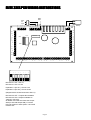
Up to 8 keypads may be connected to the panel, each with a different keypad address number.
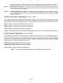
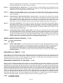
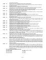
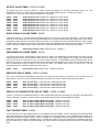
The LED indicators are used to display system conditions such as “Trouble” alarms and “Bypass” active. They
also indicate armed status of the panel and if all zones are in the clear “Ready” state prior to arming.
KEYPAD TAMPER (wrong code alarm)
A wrong code or Keypad Tamper alarm is generated by the ELITE 64 after 4 consecutive invalid code entries. A
local alarm condition will be created that may also be reported to a monitoring company via the dialler. Entry of a
valid user code will reset the Keypad Tamper alarm, however, the alarm event will be written into memory and the
keypad will display “New Event” indicating the presence of a new memory entry.
LCD QUICKVIEW MODE
If any zones are unsealed when disarmed the LCD keypad will scroll through each unsealed zone displaying the
16 character name for each zone. If a number of zones are unsealed simultaneously it can take sometime for the
display to show all of the unsealed zones.
By pressing the <ENTER> button when zones are unsealed the keypad will enter the “Quick-view” mode. When in
“Quick-view” mode, each unsealed zone is displayed as a single two digit number eg “01 05 10”. Up to 5 unsealed zones maybe displayed at one time. If more than 5 zones are unsealed at the time the display will scroll to
the next bank of 5 zones so the user can see quickly which zones are unsealed. To exit “Quick-view” mode you
simply press the <ENTER> button again or the keypad will time out automatically in approximately 30 seconds.
TOGGLE CHIME MODE ON/OFF
On the Crow LCD Keypad there is a “CHIME” button. Pressing and holding that button for two seconds will toggle
Chime Mode from On-Off or Off-On.
On the AAP LCD keypad, there is no chime button so the Control & Program buttons are used.
By pressing and holding the <CONTROL> button then within 2 seconds also pressing the <PROGRAM> button,
you will toggle Chime Mode from On-Off or Off-On.
LCD KEYPAD INSTALLATION
INSTALLATION
Separate the two keypad halves of the Arrowhead LCD Keypad by carefully inserting a small screwdriver into
the release slots on the bottom edge of the keypad front half and applying a gentle pressure. This will release the
bottom edge of the housing enough for you to unclip the top.
To separate the two keypad halves of the Crow LCD Keypads, unscrew the fastening screw at the bottom of the
keypad.
Screw the base to the wall using the mounting holes provided. These holes will match the standard single switch
plate spacing. Ensure the base is mounted right side up. It is marked with the word "TOP", on the Arrowhead keypad base, or the screw should be at the bottom on the Crow keypad base. When fixing the base to the wall make
sure the top of the screw heads will not touch or short out the underside of the PCB when the top half of the keypad is reinstalled. Bring the cables through the centre of the base.
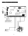
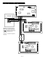
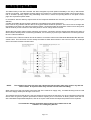
Connect the 4 wires to the 5 way terminal block on the rear of the keypad PCB making sure to match the cables
up with the terminals as marked on the control panel's keypad port. The 5th wire is an optional “Listen-in“ connection. It is connected from the "LIN" terminal of the keypad to the "Lin" terminal of the panel keypad port. With the
Listen-in wire connected the user to hear the call progress during dialling at the keypad (provided the desired program options at address P175E 6E are turned on).
Once the cables have been terminated clip the front half of the keypad onto the base.
The maximum recommended cable distance using standard 0.2mm security cable is 50m. Cable runs exceeding
this distance may require 0.5mm cable. Always use good quality cable. Some installations may require CAT5 data
cable to ensure data integrity in noisy sites.
Page 11