1
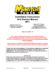
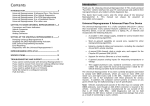
Pathfinder
TM
www.installdr.com
Nissan
Radio Replacement
Document #: 647017
1997
thru 2000
I
Click on a link
tab to jump to
that page
Cover
Page
Before
You Begin
Remove
& Install
Wire
New Radio
Mount
New Radio
Publication, Duplication, or Retransmission Of This Document Not Expressly Authorized In Writing By The Install Doctor Is Prohibited. Protected By U.S. Copyright Laws. © 1997,1998,1999,2000.
Factory Radios
With Pocket Below Radio
Other Documents Available For This Vehicle:
No documents available at this time
Adobe Acrobat Reader Printing Tips:
Double ‘DIN” Radio - No Pocket
1) Select “FILE” then “PRINT” and select your printer.
2) In the print options box do the following:
A) Locate check box “Shrink to Fit”. Place check in box.
B) Locate box “Print Quality”. Select highest print dpi
allowed by printer.
C) If print quality listed is not as high as that printers normal
quality, press the “SETUP..” button. In the next screen,
press the “PROPERTIES” button and set the printers
print quality to the highest print dpi allowed.
Document Revision History
09/99
Document Creation
12/99
Photo Updates
02/2000 Updated
New Radio
Double ‘DIN’ Style Radios Instead Of A Radio
With A Pocket Below The Radio:
The Install Doctor STRONGLY recommends that you
convert your radio assembly over to the use of a
pocket below the new radio. You can purchase an
original pocket from a Nissan dealership or you can
purchase a radio installation kit pocket from a local
installation shop which is designed as an aftermarket
equivalent to the Nissan pocket.
Using a pocket eliminates the need to use a radio
installation kit to mount a new radio into this vehicle
and keeps the appearance that the new radio was
installed by the automaker.
All Information, Including Photos And Illustrations, In These Pages Is Believed To Be Correct And Reliable. The Information Contained In These Pages Is Given As General Information For The Installation Of Audio, Video, Security,
Communications, And Other Accessory Products Into Mobile And/Or Vehicle Applications. The Install Doctor, Any Subsidiaries Or Divisions Thereof, Or Any Member Of These Companies Shall Not Be Held Liable For Any Damages And/Or Injuries
Resulting From The Use Of Information Contained In These Pages. All Information Contained In These Pages Should Be Checked And Verified With Appropriate Test Equipment To Assure The Safety And Proper Operation Of Equipment Installed
And The Vehicle Itself. Careful Attention Should Be Given To All Electronic/Electric Circuits. High Voltages And Currents Can Cause Bodily Injury, Skin Damage, And Even Death. Installs Are Taken At The Risk Of Each Installer, And/Or Individual.
Pathfinder
TM
www.installdr.com
Nissan
Radio Replacement
Document #: 647017
1997
thru 2000
I
Click on a link
tab to jump to
that page
Cover
Page
Before
You Begin
Remove
& Install
Wire
New Radio
Mount
New Radio
Publication, Duplication, or Retransmission Of This Document Not Expressly Authorized In Writing By The Install Doctor Is Prohibited. Protected By U.S. Copyright Laws. © 1997,1998,1999,2000.
Overview Of This Radio Install
Step
Remove old radio from dash
Wire the new radio
Mount the new radio
Finishing the installation
Parts Needed For This Radio Install
What Section To Go To
Remove & Install
Wire New Radio
Mount New Radio
Remove & Install
Parts REQUIRED for the install
Snap on in dash wire harness
Antenna adapter
Description
Nissan 95 and newer harness
Nissan “diversity” adapter
Optional parts for this install
None
Tools Needed To Complete This Install
TOOL TIPS:
#2
Phillips
Solder/
Crimper
Hand tools needed
to remove radio
Voltage
Meter
Small
Battery
Accessory tools needed to test and
wire the new radio
PLUS: Wire ties or electrical tape: to neatly bundle and organize your
wires for a professional appearance.
Small Battery: use a battery to test speaker wires. Touching the (+) positive
and (-) negative baterry leads to a pair of speaker will cause the speaker to
make a “Pop” sound indicating that pair of wires goes to that speaker.
Voltage Meter: Always check +12 Volt power wires for voltage before
making wire connections. These wires will fluctuate between 10 and 14 Volts.
Solder Iron or Crimp Tool: make wire to wire connections using either a
solder iron and electrical tape, OR plastic crimp terminals found at most
hardware or auto parts stores.
Installation Difficulty Ratings
Easy. No advanced skills or specialty tools needed.
Basics. Simple tools required. Installs quickly.
Intermediate. Requires knowledge of tools, or disassembly of panels.
Advanced. Requires advanced tools, or extra time.
Difficult. Involves modifying or cutting of the installation area. Advanced
tools and/or skills required. Best if performed by experienced installers.
Do It Yourselfers
Basics
Professional Installer
Basics
Support Information If You Need Help
Supplemental information if you need help
Document Title
Basic DC electronics for automotive applications
Wire splicing: soldering vs. crimping
Why use radio installation kits
Mounting your radio to an installation kit
Why use an optional snap on wire harness
Wiring your new radio using a wire harness
Testing wires when installing a new radio
Document #
999001
999004
999005
999007
999008
999009
999013
All Information, Including Photos And Illustrations, In These Pages Is Believed To Be Correct And Reliable. The Information Contained In These Pages Is Given As General Information For The Installation Of Audio, Video, Security,
Communications, And Other Accessory Products Into Mobile And/Or Vehicle Applications. The Install Doctor, Any Subsidiaries Or Divisions Thereof, Or Any Member Of These Companies Shall Not Be Held Liable For Any Damages And/Or Injuries
Resulting From The Use Of Information Contained In These Pages. All Information Contained In These Pages Should Be Checked And Verified With Appropriate Test Equipment To Assure The Safety And Proper Operation Of Equipment Installed
And The Vehicle Itself. Careful Attention Should Be Given To All Electronic/Electric Circuits. High Voltages And Currents Can Cause Bodily Injury, Skin Damage, And Even Death. Installs Are Taken At The Risk Of Each Installer, And/Or Individual.
Pathfinder
TM
www.installdr.com
Nissan
I
1997
thru 2000
Radio Replacement
Document #: 647017
Click on a link
tab to jump to
that page
Cover
Page
Before
You Begin
Remove
& Install
Wire
New Radio
Mount
New Radio
Publication, Duplication, or Retransmission Of This Document Not Expressly Authorized In Writing By The Install Doctor Is Prohibited. Protected By U.S. Copyright Laws. © 1997,1998,1999,2000.
Remove Factory Radio
STEP 1:
STEP 2:
The plastic dash panel surrounding the radio
and air conditioner controls must be removed
before removing the radio.
When both screws have been removed, the dash can then be unsnapped from the main dash.
Locate and remove two (2) phillips screws
located on the bottom of the plastic dash panel.
(these screws will not be visible unless you
look up at the bottom of the plastic panel)
Pull the bottom of the dash until the dash panel begins to unsnap, then continue up the panel until
the plastic panel has separated from the main dash.
Unplug 2 connectors attached to the rear of the cigarette lighter. Unplug 2 connectors from the
rear of the hazard and defrost switches. (if your vehicle has a rear window wiper switch on
the lower left of the plastic dash panel, you can swing the dash panel off to the left so you can
gain access to the radio - as seen in the photo above)
Double ‘DIN’ Style Radios Instead
Of A Radio With A Pocket Below
The Radio:
STEP 3:
Once the plastic panel is removed, the radio and screws securing the radio can now be seen.
The radio is secured to the pocket below the radio by metal brackets on each side of the radio/
pocket assembly. To remove the radio/pocket assembly locate and remove four (4) phillips
screws, 2 on each side of the radio/pocket assembly.
Once the screws are removed, pull the radio/pocket assembly out of the dash.
Unplug 2 white connectors plugged into the rear of the radio. Unplug the single black cable
plugged into the rear of the radio.
Once all connectors have been unplugged, pull the radio/pocket assembly completely out of the
dash.
The Install Doctor STRONGLY
recommends that you convert your
radio assembly over to the use of a
pocket below the new radio. You can
purchase an original pocket from a
Nissan dealership or you can
purchase a radio installation kit
pocket from a local installation shop
which is designed as an aftermarket
equivalent to the Nissan pocket.
Using a pocket eliminates the need to
use a radio installation kit to mount a
new radio into this vehicle and keeps
the appearance that the new radio
was installed by the automaker.
All Information, Including Photos And Illustrations, In These Pages Is Believed To Be Correct And Reliable. The Information Contained In These Pages Is Given As General Information For The Installation Of Audio, Video, Security,
Communications, And Other Accessory Products Into Mobile And/Or Vehicle Applications. The Install Doctor, Any Subsidiaries Or Divisions Thereof, Or Any Member Of These Companies Shall Not Be Held Liable For Any Damages And/Or Injuries
Resulting From The Use Of Information Contained In These Pages. All Information Contained In These Pages Should Be Checked And Verified With Appropriate Test Equipment To Assure The Safety And Proper Operation Of Equipment Installed
And The Vehicle Itself. Careful Attention Should Be Given To All Electronic/Electric Circuits. High Voltages And Currents Can Cause Bodily Injury, Skin Damage, And Even Death. Installs Are Taken At The Risk Of Each Installer, And/Or Individual.
Pathfinder
TM
www.installdr.com
Nissan
Radio Replacement
Document #: 647017
1997
thru 2000
I
Click on a link
tab to jump to
that page
Cover
Page
Before
You Begin
Remove
& Install
Wire
New Radio
Mount
New Radio
Publication, Duplication, or Retransmission Of This Document Not Expressly Authorized In Writing By The Install Doctor Is Prohibited. Protected By U.S. Copyright Laws. © 1997,1998,1999,2000.
Mounting The Radio
Wiring The New Radio
Move to: Wire New Radio Section
Required Nissan Antenna Adapter
Nissan vehicles use an odd antenna connector
designed specifically for Nissan radios only. This
antenna connector will not fit into a new radio. You
will need a Nissan “diversity” antenna adapter
which converts the odd antenna connector over to a
standard connector that will fit into your new radio.
Move to: Mounting New Radio Section
The Install Doctor STRONGLY recommends
purchasing a ‘DIN’ radio for this vehicle.
‘DIN’ radios are a direct replacement for the
radio in this vehicle. More information is
available in the “Mounting New Radio”
section.
Nissan ‘Diversity” Antenna Cable
Standard Antenna Cable And Connector
Completing The Radio Installation
This information is shown in more detail
in the “Mounting New Radio” section
Nissan radio attached to
the metal brackets and
pocket below the radio
New radio attached to
the metal brackets and
pocket below the radio
STEP 1:
STEP 2:
As shown in the “Mount New Radio” section, unscrew the Nissan radio from the
brackets and pocket below the radio, leaving the pocket attached to the brackets.
Insert and attach the new radio into the brackets.
Depending upon the radio, you may be able to use these
screws with the new radio, if not the new radio should
have 4 screws packaged with it to allow you to mount the
radio to brackets.
All Information, Including Photos And Illustrations, In These Pages Is Believed To Be Correct And Reliable. The Information Contained In These Pages Is Given As General Information For The Installation Of Audio, Video, Security,
Communications, And Other Accessory Products Into Mobile And/Or Vehicle Applications. The Install Doctor, Any Subsidiaries Or Divisions Thereof, Or Any Member Of These Companies Shall Not Be Held Liable For Any Damages And/Or Injuries
Resulting From The Use Of Information Contained In These Pages. All Information Contained In These Pages Should Be Checked And Verified With Appropriate Test Equipment To Assure The Safety And Proper Operation Of Equipment Installed
And The Vehicle Itself. Careful Attention Should Be Given To All Electronic/Electric Circuits. High Voltages And Currents Can Cause Bodily Injury, Skin Damage, And Even Death. Installs Are Taken At The Risk Of Each Installer, And/Or Individual.
Pathfinder
TM
www.installdr.com
Nissan
1997
thru 2000
Radio Replacement
Document #: 647017
I
Click on a link
tab to jump to
that page
Cover
Page
Before
You Begin
Remove
& Install
Wire
New Radio
Mount
New Radio
Publication, Duplication, or Retransmission Of This Document Not Expressly Authorized In Writing By The Install Doctor Is Prohibited. Protected By U.S. Copyright Laws. © 1997,1998,1999,2000.
STEP 3:
STEP 4:
Once the new radio has been attached to the
brackets and pocket, you can insert the radio/pocket
assembly back into the dash.
Reattach the plastic dash panel that surrounds the
radio. Reconnect all connectors that had been
attached to the rear of the plastic panel. Secure the
lower part of the plastic dash panel with the 2 phillips
screws at the bottom of the plastic dash panel.
Plug the Nissan antenna adapter into the cable that
was unplugged from the rear of the Nissan radio.
Plug the other end of the antenna adapter into the
rear of the new radio. Make sure all wire
connections for the new radio have been completed
and plug in any of the new radios connectors into the
rear of the new radio.
The installation is now complete.
Insert the radio/pocket assembly back into the dash
and secure the brackets with the same screws that
had originally secured the auto makers factory radio.
All Information, Including Photos And Illustrations, In These Pages Is Believed To Be Correct And Reliable. The Information Contained In These Pages Is Given As General Information For The Installation Of Audio, Video, Security,
Communications, And Other Accessory Products Into Mobile And/Or Vehicle Applications. The Install Doctor, Any Subsidiaries Or Divisions Thereof, Or Any Member Of These Companies Shall Not Be Held Liable For Any Damages And/Or Injuries
Resulting From The Use Of Information Contained In These Pages. All Information Contained In These Pages Should Be Checked And Verified With Appropriate Test Equipment To Assure The Safety And Proper Operation Of Equipment Installed
And The Vehicle Itself. Careful Attention Should Be Given To All Electronic/Electric Circuits. High Voltages And Currents Can Cause Bodily Injury, Skin Damage, And Even Death. Installs Are Taken At The Risk Of Each Installer, And/Or Individual.
Pathfinder
TM
www.installdr.com
Nissan
1997
thru 2000
Radio Replacement
Document #: 647017
I
Cover
Page
Click on a link
tab to jump to
that page
Before
You Begin
Remove
& Install
Wire
New Radio
Mount
New Radio
Publication, Duplication, or Retransmission Of This Document Not Expressly Authorized In Writing By The Install Doctor Is Prohibited. Protected By U.S. Copyright Laws. © 1997,1998,1999,2000.
Step By Step Wiring
Page 1 of 2
Auto Makers
Factory
Radio
New Radio
Wire Harness Inside Vehicles
Dash Which Plugs Into The
Rear Of The Factory Radio
Optional Snap On Wire Harness
(Strongly Recommended) That
Splices Into The Wires Of The
New Radio
(Note: the radio shown is for display purposes and may not be similar in
size or dimensions than the auto makers factory radio in your vehicle)
Wiring Instructions:
The power and speaker wires needed to connect the new radio are attached to
the connector of the wire harness located inside the vehicles dash. The Install
Doctor STRONGLY recommends using an optional snap on wire harness that is
specifically designed to snap into the vehicles dash wire harness connector.
This will keep you from cutting the vehicles wires. This optional snap on wire
harness will have wires on the opposite side of the connector that will allow you
to splice these wires to the new radios wires. The only other option is to cut off
the vehicles dash wire harness connector and splice the new radios wires
directly to these wires. The optional snap on wire harness takes all the guess
work out of trying to figure out what each wire is in the vehicles dash wire
harness. The optional snap on wire harness shows you what each wire is.
Supplemental information if you need help
Document Title
Testing wires when installing a new radio
Why use an OEM snap on wire harness
Wiring your new radio using a wire harness
Wire splicing: soldering vs. crimping
Document #
999013
999008
999009
999004
STEP 1
Ground Wire
STEP 2
+12 Volt
Battery Wire
Connect the +12 Volt Battery or Constant wire of the new radio to
either the +12 Volt Battery wire of a snap on wire harness OR connect
this wire to the +12 Volt Battery wire found in the wire chart above.
+12 Volt
Battery Wire
STEP 3
+12 Volt
Ignition Wire
Connect the +12 Volt Ignition or Switch wire of the new radio to
either the +12 Volt Ignition wire of a snap on wire harness OR connect
this wire to the +12 Volt Ignition wire found in the wire chart above.
+12 Volt
Ignition Wire
STEP 4
Power Antenna
Wire (if available)
If your vehicle has a POWER ANTENNA connect the
POWER ANTENNA wire of the new radio to either the POWER
ANTENNA wire on a snap on wire harness OR wire in chart above.
Power Antenna
Wire (if available)
STEP 5
Left Front Speaker Wires
Connect the LEFT FRONT speaker wires from the new radio to the
LEFT FRONT speaker wires on a snap on wire harness OR the
LEFT FRONT speaker wires found in the chart above.
Left Front Speaker Wires
STEP 6
Right Front Speaker Wires
Connect the RIGHT FRONT speaker wires from the new radio to the
RIGHT FRONT speaker wires on a snap on wire harness OR the
RIGHT FRONT speaker wires found in the chart above.
Right Front Speaker Wires
STEP 7
Left Rear
Speaker Wires
Connect the LEFT REAR speaker wires from the new radio to the
LEFT REAR speaker wires on a snap on wire harness OR the
LEFT REAR speaker wires found in the chart above.
Left Rear
Speaker Wires
STEP 8
Right Rear Speaker Wires
Connect the RIGHT REAR speaker wires from the new radio to the
RIGHT REAR speaker wires on a snap on wire harness OR the
RIGHT REAR speaker wires found in the chart above.
POWER AND SPEAKER WIRES FROM THE VEHICLES
DASH WIRE HARNESS OR SNAP ON WIRE HARNESS
POWER AND SPEAKER WIRES FROM NEW RADIO
Ground Wire
If you mount the new radio to the metal brackets originally attached to
the Nissan radio, the radio will automatically GROUND to the metal of
the vehicles dash when you screw the brackets into the dash.
Right Rear Speaker Wires
All Information, Including Photos And Illustrations, In These Pages Is Believed To Be Correct And Reliable. The Information Contained In These Pages Is Given As General Information For The Installation Of Audio, Video, Security,
Communications, And Other Accessory Products Into Mobile And/Or Vehicle Applications. The Install Doctor, Any Subsidiaries Or Divisions Thereof, Or Any Member Of These Companies Shall Not Be Held Liable For Any Damages And/Or Injuries
Resulting From The Use Of Information Contained In These Pages. All Information Contained In These Pages Should Be Checked And Verified With Appropriate Test Equipment To Assure The Safety And Proper Operation Of Equipment Installed
And The Vehicle Itself. Careful Attention Should Be Given To All Electronic/Electric Circuits. High Voltages And Currents Can Cause Bodily Injury, Skin Damage, And Even Death. Installs Are Taken At The Risk Of Each Installer, And/Or Individual.
Pathfinder
TM
www.installdr.com
Nissan
I
1997
thru 2000
Radio Replacement
Document #: 647017
Click on a link
tab to jump to
that page
Cover
Page
Before
You Begin
Remove
& Install
Wire
New Radio
Mount
New Radio
Publication, Duplication, or Retransmission Of This Document Not Expressly Authorized In Writing By The Install Doctor Is Prohibited. Protected By U.S. Copyright Laws. © 1997,1998,1999,2000.
Radio Wire & Color Code Information
A
C
D
E
B
G
H
F
K
L
M
N
I
J
O
P
AS VIEWED FROM MATING END OF CONNECTOR
Factory in-dash wire harness (this vehicle has a 2 pc
harness) that snaps into the factory radio
Page 2 of 2
Pin
What It Is
A
B
C
D
E
F
G
H
I
J
K
L
M
N
O
P
Right Rear Speaker (+)
Amplifier Turn On Wire
Right Rear Speaker (-)
Left Rear Speaker (+)
Left Rear Speaker (-)
Amp Ground Wire
+12 Volt Ignition Wire
Right Front Speaker (+)
Left Front Speaker (+)
Ground Wire (if available)
+12 Volt Battery Wire
Power Antenna Wire
Right Front Speaker (-)
Left Front Speaker (-)
Typical Nissan
In Dash Wire Color
Typical New Radio
Equivalent Wire Color
Orange
Purple
Blue or Blue w/ White
Black w/ Pink Stripe
Purple w/ Black Stripe
Lite Green
Green
Black w/ Yellow Stripe
Green w/ Black Stripe
connect this wire to the radios ground wire
Green w/ Red Stripe
Red
Do Not Use
Brown
Gray
Blue
White
metal brackets on radio
Black
Do Not Use
Red w/ Yellow Stripe
Yellow
Blue
Black w/ Red Stripe
Gray w/ Black Stripe
Black w/ White Stripe
White w/ Black Stripe
Note: using an optional snap on wire harness adapter will simplify the wiring. Most snap on
wire harness adapters have already converted and color coded the wires from the auto
makers in dash wire harness to match typical aftermarket radio wire colors.
** The wire colors listed in the chart above are typical for this vehicle manufacturer during
these years but may not be the exact colors for this vehicle. This is another reason to use a
snap on wire harness adapter. **
Wiring Note:
Most Nissan Pathfinders will have an additional amplifier connected to the Nissan stereo. This amplifier will power the speakers
inside the vehicle instead of the amplifier inside the radio.
The Install Doctor recommends “integrating” into this Nissan amplifier when wiring the new replacement radio. This means that
the Nissan amplifier will power the speakers in the vehicle instead of the amplifier inside the new replacement radio.
To “integrate” into the Nissan amplifier you will simply wire the new radio just as you would if there was no amplifier in the vehicle.
The only difference in the wiring is that you will need to activate or turn on the amplifier when the new radio turns on. In order to
turn on the Nissan amplifier, two wires in the wire harness connector in the dash need to be connected to the new radio.
These two wires are located on the smaller of the two white connectors of the radio wire harness located in the dash. One of
these wires is a (+) 12 Volt wire which connects to the new radios power antenna turn on wire (some new radios may actually
have an amplifier turn on wire in addition to a power antenna turn on wire). This wire will tell the Nissan amplifier to turn on and
off when the new radio turns on and off. The second wire, also located on the smaller of the two white connectors, is a (-)
Ground wire for the Nissan amplifier. This wire needs to be connected to the new radios Ground wire.
If you follow The Install Doctors installation procedures and mount your new radio to the metal brackets originally mounted to the
Nissan radio, you will actually ground the radio through the metal brackets when the brackets are screwed into the dash.
Connecting the Nissan amps ground wire to the new radios ground wire will ground the amp as well through the metal brackets.
This method is probably the best method to connect and turn on the Nissan amplifier and does not require alot of additional
wiring.
All Information, Including Photos And Illustrations, In These Pages Is Believed To Be Correct And Reliable. The Information Contained In These Pages Is Given As General Information For The Installation Of Audio, Video, Security,
Communications, And Other Accessory Products Into Mobile And/Or Vehicle Applications. The Install Doctor, Any Subsidiaries Or Divisions Thereof, Or Any Member Of These Companies Shall Not Be Held Liable For Any Damages And/Or Injuries
Resulting From The Use Of Information Contained In These Pages. All Information Contained In These Pages Should Be Checked And Verified With Appropriate Test Equipment To Assure The Safety And Proper Operation Of Equipment Installed
And The Vehicle Itself. Careful Attention Should Be Given To All Electronic/Electric Circuits. High Voltages And Currents Can Cause Bodily Injury, Skin Damage, And Even Death. Installs Are Taken At The Risk Of Each Installer, And/Or Individual.
Pathfinder
TM
www.installdr.com
Nissan
Radio Replacement
Document #: 647017
1997
thru 2000
I
Click on a link
tab to jump to
that page
Cover
Page
Before
You Begin
Remove
& Install
Wire
New Radio
Mount
New Radio
Publication, Duplication, or Retransmission Of This Document Not Expressly Authorized In Writing By The Install Doctor Is Prohibited. Protected By U.S. Copyright Laws. © 1997,1998,1999,2000.
Mounting A Radio
NOTE:
Before you begin: The best method to mount a new radio in this vehicle is to
unscrew the auto makers factory radio from the brackets attached to the radio
and screw the new radio into these brackets just as the factory radio was. This
keeps the vehicle looking as stock from the factory as possible and means that
you do not have to purchase an installation kit to mount the radio.
This method is called “ISO” mounting a radio. “ISO” mounting a radio has become a very
common installation method for mounting new replacement radios. In order to “ISO” mount
your radio, three things must exist:
1)
2)
All information needed to complete an ‘ISO’ mounting of the new
radio to the brackets originally attached to the factory radio is
included on this page. If you are installing a “shafted” style radio
or you will be using an installation kit to mount your new radio
instead of the ‘ISO’ mounting method, you can find additional
help in the following tech documents:
Document Title
Why use radio installation kits
Mounting your radio to an installation kit
Radio security
Document #
999005
999007
999010
The radio must be a ‘DIN’ style rectangular radio
The ‘DIN’ radio must have mounting holes predrilled into both sides of the radio to
allow the radio to be secured with screws to the brackets originally attached to the
factory radio.
The radio must have a removable trim ring surrounding the face of the radio
3)
Remove the auto makers factory radio/pocket assembly from the vehicle. Remove the screws/bolts securing the
radio to the brackets which are also attached to the sides of the pocket below the radio.
1
Removal Tip: some auto makers use phillips screws, some use 8 mm bolts with phillips screw cutouts in the top
of the bolts. For best results use a socket to prevent stripping out the screws. If your radio has hard to remove
phillips screws, insert the tip of the phillips screwdriver into each phillips screw and firmly tap with a hammer to loosen the
tension bond between the phillips screws and the metal chassis of the auto makers factory radio. Then attempt to
unscrew the phillips screws.
Auto makers original radio with
attached pocket below the radio
Remove the auto makers factory radio, but leave the brackets attached to the pocket.
2
What if you do not have a pocket? If the radio in your vehicle was a Double ‘DIN’ radio (or it did NOT have the
pocket below the factory radio) The Install Doctor STRONGLY recommends that you convert your radio
assembly over to use a pocket below the radio. You can purchase the pocket from a Nissan dealership or
you can purchase a “multi” pocket radio installation kit that is designed to fit bracket-pocket applications such as
this application. Once you have the pocket, secure the pocket to the metal brackets and you can avoid using
radio installation kits to mount the new radio to the dash.
On the side of the new ‘DIN’ radio should be pre-drilled holes to allow you to screw the new
radio into the brackets. Most car radio manufacturers design their radios with many holes on
the side of the radio so the radio can be mounted to many different kinds of bracket/pocket
configurations.
3
New radio
If you are going to mount your radio in this manner, you will probably have to remove the
radios face trim ring around the face of the radio. This trim ring will most likely prevent the
vehicles dash panel from securing properly back onto the dash.
New radios removable trim ring
surrounds the face of the radio
4
A common mistake when mounting your new radio to the auto makers radio bracket
and pocket is selecting the wrong holes on the side of the new radio.
The new radio body, NOT THE FACE PLATE, should line up with the pocket below
the radio. Most new radio manufacturers design their radios with a face that protrudes
out from the body of the radio. The most common mistake is to mount the new radio
with the protruded face lined up level with the pocket below the radio, not the new
radios body.
New radio attached to the auto
makers pocket and brackets
Line up
like this
All Information, Including Photos And Illustrations, In These Pages Is Believed To Be Correct And Reliable. The Information Contained In These Pages Is Given As General Information For The Installation Of Audio, Video, Security,
Communications, And Other Accessory Products Into Mobile And/Or Vehicle Applications. The Install Doctor, Any Subsidiaries Or Divisions Thereof, Or Any Member Of These Companies Shall Not Be Held Liable For Any Damages And/Or Injuries
Resulting From The Use Of Information Contained In These Pages. All Information Contained In These Pages Should Be Checked And Verified With Appropriate Test Equipment To Assure The Safety And Proper Operation Of Equipment Installed
And The Vehicle Itself. Careful Attention Should Be Given To All Electronic/Electric Circuits. High Voltages And Currents Can Cause Bodily Injury, Skin Damage, And Even Death. Installs Are Taken At The Risk Of Each Installer, And/Or Individual.