1
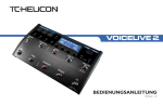
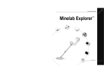
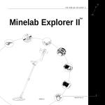
INSTRUCTION MANUAL The Minelab SD2200v2 MINELAB ELECTRONICS PTY LTD 118 Hayward Avenue, Torrensville, SA 5031, Australia PO Box 537, Torrensville Plaza, SA 5031, Australia Telephone: +618 8238 0888 Facsimile: +618 8238 0890 Email: [email protected] MINELAB INTERNATIONAL LTD Laragh, Bandon Co Cork, Ireland Telephone: +353 23 52101 Facsimile: +353 23 52106 Email: [email protected] MINELAB USA INC. 871 Grier Dr., Suite B1 Las Vegas, NV 89119, USA Telephone: +1 702 891 8809 Facsimile: +1 702 891 8810 Email: [email protected] www.minelab.com MINELAB MINELAB WARNING THIS DOCUMENT CONTAINS MINELAB ELECTRONICS LIMITED RIGHTS TECHNICAL DATA, OR RESTRICTED RIGHTS DATA, OR BOTH. © Minelab Electronics Pty Limited This work is copyright. Apart from any use as permitted under the Copyright Act 1968, no part may be reproduced by any process without prior written permission from Minelab Electronics Pty Limited 118 Hayward Avenue, Torrensville, SA 5031 Australia. 4901-0042-1.2 Page 2 The Minelab SD2200v2 The Minelab SD2200v2 Instruction Manual 1. Contents Page No. 1. Introduction ................................................................................................ 3 2. List of Parts ................................................................................................ 5 3. Unpacking and Assembly .......................................................................... 6 4. Control Box ................................................................................................. 8 5. 6. 7. 4.1 Rear Panel Controls ........................................................................ 8 4.2 Front Panel Controls ..................................................................... 10 Operation ................................................................................................. 12 5.1 Quick Start Instructions ................................................................. 12 5.2 Operating Instructions .................................................................. 13 Auxiliary Parts ......................................................................................... 23 6.1 Battery ........................................................................................... 23 6.2 Battery Chargers ........................................................................... 23 Detecting Techniques ............................................................................. 25 7.1 Searching ...................................................................................... 25 7.2 Prospecting Tips ........................................................................... 26 7.3 Hints for Maximum Gold Recovery ............................................... 27 7.4 Identifying Target Signals ............................................................. 27 7.5 Pinpointing .................................................................................... 28 7.6 Digging the Target ........................................................................ 29 7.7 Salty Environments ....................................................................... 30 8. Maintenance ............................................................................................ 31 9. Troubleshooting ...................................................................................... 32 10. Specification ............................................................................................ 33 11. Warranty .................................................................................................. 34 12. Instruction Manual Accessories ............................................................................................ 35 12.1 Search Coils ................................................................................. 35 12.2 Batteries ........................................................................................ 36 12.3 Corporate Clothing ....................................................................... 36 Page 3 Introduction The SD2200v2 has been developed by improving and redesigning the SD2100 technology to include a number of new functions. The new features of the SD2200v2 are: two discrimination settings, automatic ground balance, audio boost control and auto tuning control. Minelab is confident that you will find this detector to be the finest available for the detection of metallic objects in highly mineralised environments. The SD2200v2 can see deeper than any conventional detector available on the market. Its simple operation means that the beginner and professional will find it easy to use. Its superior ability to cancel mineralisation using automatic ground balance, as well as discriminating between ferrous and non-ferrous items, makes this machine easier and faster to use than ever before. It will re-open old gold fields where mineralised, or hot ground and too much rubbish have shielded many nuggets from the prying eyes of other detector operators. Minelab has studied the role that magnetic soil chemistry or so-called mineralisation plays in obscuring nuggets and has developed Multi-Period Sensing (MPS) technology. This technology enables detection of metallic targets, both large and small, even in the most mineralised or hottest ground. The unit also provides an automatic ground balancing facility, which makes maintaining optimum ground balance a simple operation in a variety of ground types. Included into the circuitry of the SD2200v2 are memory chips. These allow the detector to remember the last ground balance and tune settings when switched off. These memory functions also assist in the accurate discrimination of ferrous targets in highly mineralised soil plus assist the audio booster built into the machine. We trust you will find this detector a pleasure to use with its stable and effective ground balancing, superior depth capability and sensitivity. Since there may be a range of options available in this detector type, equipment may vary according to the model or country of issue. Certain descriptions and illustrations may differ (in this manual) from the exact model that you have purchased. In addition, Minelab reserve the right to respond to ongoing technical progress by introducing changes in design, equipment and technical features at any time. Page 4 The Minelab SD2200v2 Instruction Manual 2. Page 5 List of Parts The SD2200v2 is packed in a single box containing the detector and an 11 Double D coil. The following parts are included (see figure 1): Part 1. 2. 3. 4. 5. 6. 7. 8. 9. 10. 11. 12. 13. 14. 15. 16. 17. 18. 19. Figure 1 - SD2200v2 Parts List 20. 21. 22. 23. 24. 25. 11 Double D Coil with Skidplate 11 Monoloop Coil with Skidplate (accessory) 18 Monoloop Coil with Skidplate (accessory) 8 Monoloop Coil with Skiplate (accessory) SD2200v2 Control Box Complete Shaft Assembly Armrest (2 halves) 1½ Nylon Bolts (2) Nylon Wing Nuts (2) Armrest Cover Armrest Strap 6V 12Ah Gell Cell Battery Battery Backpack & Harness Battery Cable 12V Car Charger Mains Charger Headphones Bungy Strap Teardrop Washers (4) 2 Nylon Bolts (2) Nylon Wing Nuts (2) Velcro Tape and Hook SD2200v2 Instruction Manual Warranty Card Attention Card Rubbish Bag SD2200v2 Field Guide Carton and Insert Item Number 2021-0011 2021-0027 2018-0028 2021-0009 8012-0029 8001-0014 4001-0001 4002-0003 8001-0012 8005-0019 0311-0024 3001-0028 3011-0043 0312-0024 Region Spec 4523-0018 8006-0002 4005-0006 4001-0003 4002-0003 8507-0001/2 4901-0042 Region Spec 5303-0006 5302-0006 4903-0024 Page 6 3. The Minelab SD2200v2 Unpacking and Assembly a) Place the two armrest halves (7) on either side of the shaft assembly (6) and ensure that the bolt holes line up. b) Slide two nylon bolts (8) through the holes and screw nylon wing nuts (9) onto the bolts with a couple of turns. c) Slide the T section on top of the control box (5) into the assembled armrest (7) (with the detector stand at the rear). Tighten the nylon wing nuts (9) by hand. d) Push the armrest cover (10) over the assembled armrest (7). Instruction Manual j) Page 7 Fit the battery (12) into the battery bag (13). k) Plug the headphones (17) into the socket in the cap of the battery. l) Put on the battery bag (13). Ensure that the Power switch on the control box is set to Off. Plug the connector on the bag cable into the Power connector on the control box. This cable connects the battery and headphones to the detector. The bungy cord (18) can be attached to the knuckle on the shaft to take some of the weight when prospecting. An adjustable hand strap on the handle allows you to relax and flex your fingers without putting the detector down. e) Ensure that the lower shaft has two teardrop rubber washers (19) installed. They should always be full thickness and should be replaced regularly as they wear out. f) Push the lower shaft into the mounting bracket on the coil (1) and ensure that the coil decal faces the front. g) Align the holes in the coil mounting bracket and the lower shaft. Push a nylon bolt (19) through the holes and fit a nylon wing nut (19) which should be tightened by hand. DO NOT over tighten as the coil housing may be damaged. h) Adjust the shaft length and coil angle for a comfortable position. Minelab recommends that the shaft length be set to give a comfortable sweep length of approximately 2 metres (see section 7 for more details on detecting techniques). i) Wind the coil cable around the shaft and plug the coil connector into the coil socket on the control box. Ensure that the cable is firmly attached to the shaft without strain and cannot move around, especially near the coil. Fasten the cable to the shaft with the supplied VelcroTM straps (19). Leave enough slack at the bottom of the cable near the coil to allow the coil angle to be adjusted without placing strain on the coil cable. If the cable is able to move around, especially near the coil, it will be seen by the detector and cause random noises, which can be very confusing. Note: Always ensure that the Power switch on the control box is turned Off before connecting or disconnecting the coil. Figure 2 - SD2200v2 Battery Assembly Page 8 The Minelab SD2200v2 4. Control Box 4.1 Rear Panel Controls 4.1.1 Power Switch The Power switch controls the power supply from the battery to the control box. Always switch the detector Off before connecting or disconnecting the coil or battery, and when not in use. 4.1.2 Channel Switch (Ch1, Ch2, Both) The Channel switch selects the channel used for searching: Ch1, Ch2 or Both. Searching is usually done in the Both position which gives the maximum sensitivity to the greatest range of targets. When detecting in highly noisy ground, the selection of Ch1 rather than Both might improve the stability of the threshold. However, sensitivity to certain types of targets is reduced when using only Ch1 and is not recommended. 4.1.3 Instruction Manual 4.1.5 Page 9 Tune The Tune control is used to lower the effects of electromagnetic interference from sources such as power lines, radio transmitters and other metal detectors. The Tune control is engaged by pressing the push button switch. If electromagnetic interference is experienced when using the detector, simply press the Tune button once to automatically select the best detection frequency. 4.1.6 Tone The Tone control can be adjusted to suit an individuals hearing by changing the pitch of the background threshold tone. Threshold The Threshold is used to adjust the loudness of background sound. Minelab recommends a soft audible headphone signal which is comfortable to listen to for extended periods. 4.1.4 Boost Switch (Shallow, N, Deep) The Boost switch can be used to enhance the signals produced by different types of targets. In the Shallow position, signals from small targets close to the surface of the ground will be amplified, allowing easier detection of such targets. This option is best suited for quiet ground. For normal detecting conditions use the N position which responds to all signals without boosting. The Deep position is recommended when looking for big targets at greater depth in noisy ground. In this mode random soil signals are smoothed, making small changes in the audio signal from large deep targets easier to hear. It may, however, mask some signals from very small targets near the surface. Figure 3 - Rear Panel Controls Page 10 The Minelab SD2200v2 4.2 Front Panel Controls 4.2.1 Ground Balance Mode (Fixed or Tracking) To get the best from your SD2200v2, it is important to know how different ground conditions affect the detecting process. Ground contains not only sand, but also many different chemicals, minerals and salts. These extra components are referred to as ground mineralisation. This ground mineralisation will often produce a sound from the detector, known as ground noise. The SD2200v2 has the ability to cancel out the effects of ground mineralisation so that it minimises ground noise, while retaining maximum sensitivity to metal targets. Cancelling out the effects of ground mineralisation is referred to as ground balancing. This ensures that welcome signals from objects such as gold are not confused with unwelcome ground noise. The SD2200v2 has automatic ground balance which adjusts to minimise the effects of ground mineralisation when set in Tracking mode. 4.2.2 Instruction Manual Page 11 If the signals are too weak for accurate discrimination in either of the discriminating modes, the detector will return to the All Metal mode signal. While in the Disc + ID mode, a signal which is too strong to be discriminated will produce a rapidly pulsing signal with constant pitch. This is called an overload signal. A target producing this sound should not be interpreted as being a ferrous target but be investigated. 4.2.3 Discrimination Level Adjust The discrimination Level Adjust gives the operator the ability to select the sensitivity and likelihood of a target being ferrous or non-ferrous. The same control also affects how the detector recognises mineral effects in the ground as opposed to metal targets, when ground tracking. Iron Discriminate Switch (Disc, All Metal, Disc + ID) This switch allows you to select between simple discrimination (Disc mode) and discrimination with tone identification (Disc + ID mode), or to turn off the discrimination altogether (All Metal mode). In the case of All Metal mode, the detector will give varying volume and pitch signals but this information does not indicate the type of metal in the object found. In Disc mode, a strong signal from a ferrous (iron) object will cause the threshold to be blanked or silenced. In Disc + ID mode, a strong signal from a ferrous object will cause the threshold to be blanked, just as it does in Disc mode. In addition, a signal of medium strength will trigger the ID mode. In this mode, non-ferrous objects usually produce a tone with a steady pitch while a ferrous object will usually produce a tone with a varying pitch. Repeated sweeps across the target might be required to confirm whether the tone is steady or varying. Note, however, in this mode some non-ferrous objects can also produce a tone with varying pitch, making the operator more likely to mistake a non-ferrous object for a ferrous object. This mode of discrimination should not be trusted until the operator has sufficient experience with listening to the tones produced and comparing them with the objects detected. Figure 4 - Front Panel Controls Page 12 5. The Minelab SD2200v2 Operation These instructions can be followed by operators who are familiar with the workings and general terminology of detectors. However, Minelab recommends that as the SD2200v2 has new features and some of the functions can differ from similar functions of other detectors, all operators should read the Operating Instructions in section 5.2. 5.1 Quick Start Instructions a) Switch the Power switch to On. b) Set the Threshold control so that sound can be heard in the headphones. c) Hold the detector at waist height with the shaft horizontal, so that the coil is vertical. Keeping the coil vertical, slowly move it around your body through a half-circle until the noise from interference is loudest. Hold this position, keeping the coil motionless, and push the Tune button once to start tuning function. Tuning takes approximately one minute. A series of three beeps indicates that the best frequency has been selected. d) Rotate the Tone control to produce a threshold pitch that suits your hearing. e) Set the Channel switch to Both and the Audio/Boost switch to either Shallow for small shallow targets, Deep for large, deep targets or N (Normal) for general detecting. (see section 5.2.7) f) Set the Iron Discriminate switch to the Disc position and turn the Level Adjust to the middle of its range. g) Ground balance the detector by pulsing the coil up and down and, while coil is in motion, flick the Balance Mode switch from Fixed to Track. h) Your detector is now ready to be used. Minelab recommends that you take time to read this manual thoroughly to help get the most out of your new SD2200v2. Instruction Manual 5.2 Page 13 Operating Instructions This section gives a detailed description of how to operate the SD2200v2 detector. The section Detector sounds contains definitions of some terms with which the beginner should be acquainted. 5.2.1 Detector Sounds Threshold: This is the background sound produced by the detector. The loudness of the background sound is set with the Threshold control. Set this so that it can just be heard. The pitch of the threshold sound can be set to your preference using the Tone control. Object signal: This is an abrupt change of the pitch and volume of the threshold sound. If the pitch drops first, then rises as the coil is passed over a target, this generally (but not always) indicates a small target. If the pitch rises first then falls as the coil is passed over a target, this generally indicates a large target. The pitch variations can be different when operating in Disc + ID mode (see section 5.2.9). Ground noise: These are irregular noises that are difficult or impossible to pinpoint when moving the coil over the ground. They are caused by changing chemistry or mineralisation of the ground. While the detector is in Tracking mode these effects are minimised. 5.2.2 Turning on the SD2200v2 Hold the coil away from the ground and metal objects and switch the Power switch to On. Note: When the SD2200v2 is turned off, it saves important information (like last tuning and ground balance settings) in its internal memory. If detection is started in the same spot, the user should not have to re-tune or re-ground balance the detector. 5.2.3 Set the Threshold Control The Threshold control should be set so that background tone is barely audible. It is important to note that small surface objects, as well as large deep objects, will produce very small changes in the threshold sound. It is therefore important to set the Threshold control correctly to ensure that these targets are heard. We suggest that you experiment with known targets to assist in setting this and the other controls to suit your hearing. Page 14 5.2.4 The Minelab SD2200v2 Set the Tone Control Carefully adjust the Tone control until the threshold sound is at a comfortable pitch for your hearing. Note that interpretation of the detection signals involves understanding the difference between the rising and falling pitch of the threshold. Again, we suggest you take time to experiment with known targets. Generally, setting the Tone control at a high pitch is more fatiguing but better for identifying the faintest signals. 5.2.5 Set Tune Control With the SD2200v2 operating and the Threshold control and Tone control set: Instruction Manual Page 15 The Deep position is recommended when looking for big targets at depth. It smoothes out background sound and signals from small targets, making small changes in audio signal easier to hear. For normal detecting conditions use the N (normal) position, which does not boost any signals. Select whichever position best suits the conditions of the area you are detecting. Each time the switch is changed, the threshold will also need to be changed. External amplifiers may be used in addition to the boost switch, provided they have loudness limiters built in. This prevents loud signals becoming unpleasant or dangerous to hearing. · Hold the detector at waist height and the coil vertical. · Keeping the coil vertical, slowly move it through a half-circle around your body. Listen for an increase in interference as you move the coil. When the interference is loudest, stop moving the detector, hold it motionless in that position and momentarily press the Tune button. 5.2.7 · The detector will now scan through its range of transmission frequencies and automatically select the frequency that offers a minimum of interference. The end of the search (which takes about one minute) is announced by three beeps. The function of this switch is to select which of the channels the detector uses to generate signals. Each of the channels has a sensitivity to its own range of target types and sizes and each channel complements the other. When set to Both, the detector uses the best channel for a particular target to generate the signal. It is for this reason that Minelab recommends the use of Both in almost all circumstances. Important: While the detector is selecting the preferred frequency, the coil must be kept motionless and clear of metal objects. · In some cases it may not be possible to remove the interference completely, but the effect will be greatly reduced. · Once this control has been set for the location you are in, it should not require readjustment unless conditions change or new interference is introduced such as other detectors operating in the vicinity. 5.2.6 Boost Switch (Shallow, N, Deep) This switch is used to select the type of sound made by the detector in response to different target types. In the Shallow position, signals from small targets close to the surface are boosted. This makes it easier to hear these target signals. This setting will also tend to boost ground noise, so this setting is best used in quiet ground. Channel Switch (Ch1, Both, Ch2) In almost all circumstances, this switch should be set to Both. There are very few circumstances in which it is beneficial to use either of the other settings and to do so will reduce sensitivity to certain types of targets. Selecting Ch1 can help reduce ground noise from very noisy ground. It can sometimes stabilise the threshold which will assist in hearing faint targets in such conditions. As a result of excessive ground noise, Minelab does not recommend the use of Ch2 by itself. Setting the Channel switch to Ch1 does not affect the blanking of sounds due to ferrous targets while in Disc or Disc + ID. Note that in general, however, the signal pitch and volume in Disc + ID mode for a target will be altered. Note that the Channel switch does not affect the way in which the automatic ground balance operates. Page 16 5.2.8 The Minelab SD2200v2 Ground Balancing Automatic ground balance is active whenever the detector is set in the Tracking mode. In this mode, the detector continuously measures the effect of ground mineralisation and automatically adjusts the ground balance to compensate. Introduction The SD2200v2 can be operated with automatic ground balance (Tracking mode) or with the ground balance fixed (Fixed mode). Instruction Manual Page 17 Ground Balance Procedure Ground balance both channels at once by setting the Channel switch to Both. Move the coil up and down between 20mm and 100mm above the ground, and while moving the coil, set the Balance Mode switch from Fixed to Tracking. The fast ground balance lasts for only five seconds after switching to Tracking. Therefore, it is important to be moving the coil as the switch is thrown. When the Balance Mode switch is switched to Fixed mode, the ground balance is held at its current level. When switched from Fixed to Tracking mode, the detector begins to automatically ground balance through a process of two stages. The first stage is a very rapid adjustment to the ground mineralisation. This stage lasts for five seconds after the switch is thrown. The second stage continues to adjust to the ground mineralisation, but at a greatly reduced speed. Adjustment continues for as long as the detector is kept in Tracking mode. It may be of use to repeat the ground balance function when ground conditions change rapidly. If the detector is switched to Fixed mode at any time, it will no longer adjust itself to changes in soil mineralisation, but will stay fixed at the level it last reached while in Tracking mode. While in Tracking mode, the detector usually stops ground balancing when it detects a target. However, a weak target signal may not be recognised as a target and, if the coil is repeatedly passed over it, the target could be tracked out. It is therefore recommended to switch from Tracking to Fixed when pinpointing a potential target (see also Discrimination level control, pages 21and 22). For best results, use Tracking mode in areas with high ground noise. If the ground mineralisation is only mild or with little variability, searching in Fixed and regularly rebalancing when required can have advantages. People who have used previous SD models must note that setting the Channel switch does not affect the operation of the automatic ground balance. Figure 5 Setting Ground Balance Keep moving the coil until all ground noise has stopped. A persistent signal probably indicates a target in the ground. In this case, move the coil to a new location and repeat the procedure. When there is no longer a change in the threshold while the coil is being raised and lowered, the detector is said to be ground balanced. Once the detector is ground balanced, you can then decide to detect in either Tracking or Fixed mode. If the ground is mineralised or variable, use Tracking. If the ground is very mild, use Fixed mode and switch back to Tracking temporarily if the threshold becomes noisy. Do not test a target by switching to Tracking when the coil is above it. 5.2.9 Iron Discrimination Discrimination is the ability of a detector to distinguish between different types of metal targets and to assist the operator in identifying a target. Some goldfields are littered with junk, that is, metal objects which are of little value and are an annoyance to detector operators. The SD2200v2 is capable of rejecting a number of iron objects while still detecting non-ferrous metals. The ability of the SD2200v2 to discriminate ferrous targets means that while working these goldfields, much of the iron junk can be ignored with little fear of ignoring valuable targets. Page 18 The Minelab SD2200v2 Instruction Manual Page 19 Iron Discrimination Switch The main means of iron discrimination of the SD2200v2 is the blanking (silencing) of the threshold which occurs when the detector determines a target is of ferrous metal (magnetic). This form of iron discrimination operates when the Iron Discrimination switch is in the Disc position and the detector is fitted with the supplied 11 Double D wound coil. Targets must produce sufficiently strong signals for the SD2200v2 to successfully discriminate iron objects. Fortunately, most iron junk is located near the surface and much of it can produce the required signal strength. Note: When used in Disc mode, deeper or small targets, whether ferrous or non-ferrous, will produce the normal target audio signal. When the SD2200v2 is operated in the Disc + ID mode, the same audio blanking will operate as it did in Disc for strong signals. However, there is an additional mode of iron discrimination which can operate with weaker signals. In this case, the detector will jump into the ID audio signal mode. In Disc + ID mode, the operator needs to monitor the pitch of the signal as the coil is swept over the buried metal target. Most ferrous targets will produce a changing pitch signal as the coil is moved back and forth across the target. Non-ferrous targets will produce a signal with a steadier pitch. Some ferrous targets, particularly thin nail-like targets, can also produce steady pitches just like non-ferrous targets. Some gold will also produce a variable pitch, particularly specimen gold or gold containing a matrix of quartz and/or ironstone. Therefore, only signals with highly variable pitch can be trusted to indicating ferrous targets in the +ID mode. The +ID target mode of recognition requires a lot of operator experience. It is recommended that the operator investigate most targets detected in the +ID mode and learn to distinguish the signals. The audio blanking on ferrous targets is the most useful form of discrimination. This will only operate if a Double D coil is used. The central position of the Iron Discrimination switch activates the All Metal mode. There is no discrimination in this mode. Targets will cause pitch and volume of signals to vary, but these variations convey no consistent information about the type of metal. Figure 6 - Discrimination Levels Page 20 The Minelab SD2200v2 Instruction Manual Page 21 If a target signal is too weak for the detector to discriminate when it is set in one of the discriminating modes, it will revert to the All Metal mode. As soon as the signals become strong enough, the detector will resume discrimination. It is not advisable to pinpoint in the Disc + ID mode because the duration of the signal is too long (too broad a signal). Pinpointing is best performed in the All Metal mode. It is recommended that once a target has been located and the operator is using the discriminator, the coil should be rapidly passed back and forth over the target centre several times. Remember to switch back to Fixed balance for this. Control Rotation Anticlockwise Clockwise Discrimination Suggested for areas with small amounts of junk Suggested for areas with a lot of ferrous junk Dig more junk but less likely to cancel a gold nugget Dig less junk but may mistake a nugget for ferrous junk The form of ferrous discrimination which blanks the signal will not work if a monoloop coil is used instead of the recommended Double D. In that case the Disc mode will be identical in response to the All Metal mode. The Disc + ID mode will operate in the +ID mode giving pitch discrimination, but will still not blank ferrous signals. (+ID) function requires stronger signals to operate (+ID) function requires less strong signals to operate The operation of the Disc + ID mode is affected by signals which are too strong. If the signal is too strong in +ID mode, the detector will emit a rapidly pulsing signal of constant pitch. This is to guard against erroneous interpretation indicating an overload of signal. Lift the coil slightly higher above the ground and the discrimination functions will return. Only fairly strong target signals will trigger discrimination action The coil must at all times, particularly when discriminating or IDing a target, be passed smoothly over the surface of the ground while maintaining the coil height above the ground. The Disc mode discrimination will only blank a ferrous signal when a target gives a strong signal when passing across a piece of iron, a target response will be heard until the SD2200v2 identifies that the target is indeed iron. At this point, the signal will blank. The target strength required for this to occur can be adjusted using the Discrimination Level Adjust Control. Figure 7 - Discrimination Audio Signal Most iron objects are discriminated Almost all iron objects are but a few small iron objects will be discriminated however a few small accepted as non-ferrous non-ferrous items will be ignored Strong and medium target signals will trigger discrimination action Tracking Ground track is more likely to balance out targets Ground track is less likely to balance out some weak signals Medium to strong signal required to pause the Tracking mode Weak signal will pause the Tracking mode Suited for areas of rapidly changing Suited for areas with constant mineralisation ground mineralisation Page 22 The Minelab SD2200v2 5.2.10 Level Adjust Control There is usually some overlap between signals from useful targets and some types of iron junk. Because of this, the operator has to use the Level Adjust knob to select the amount of discrimination between two extremes: no useful target missed, but some iron getting through (anti-clockwise) and unlikely any iron detected but some small non-ferrous targets possibly missed (clockwise - see page 21) The Level Adjust gives the operator the ability to select the sensitivity and likelihood of a target being discriminated as ferrous. The same control also affects how the detector recognises ground mineralisation as opposed to metal targets, while operating in Tracking. Turning the control anti-clockwise increases the strength of a signal required for iron discrimination to be activated. Turning the control clockwise has the opposite affect, but non-ferrous targets are more likely to be mistaken for iron. The Level Adjust control has exactly the same effect in both Disc and Disc + ID positions. In the All Metal mode it effects only the Tracking mode. Set fully clockwise there is little danger of the Tracking cancelling out genuine targets, however some ground may also give a false signal. With the Level Adjust control set fully anti-clockwise most ground signals will be tracked effectively but some faint, weak target signals may be missed. Minelab recommends that it is usually best to dig out all targets and only use the discriminator in areas where the unreasonable abundance of trash makes the digging of everything impractical. Note: Discrimination functions will work only on strong, positive signals. Weak signals will give normal all metal type signals. The shape or profile of the object may also influence the ID tone on occasion. Check by passing the coil across the target several times and from a variety of directions. Instruction Manual 6. Auxiliary Parts 6.1 Battery Page 23 The 6 volt rechargeable battery supplied with your SD2200v2 will give power to operate the detector for 14 - 15hrs after being fully charged. These batteries may be recharged at any time during their discharge cycle. It is very important to fully charge the batteries before storage. Do not leave a battery fully discharged for longer than 1 day. CAUTION Only use 6v batteries as supplied. Never use a 12v battery as this will damage the detecor. This damage is not covered by warranty. 6.2 Battery Chargers Two types of battery chargers (mains and 12 volt car charger) are supplied with the SD2200v2. 6.2.1 Charging Batteries · Turn the SD2200v2 off before disconnecting the battery. · Disconnect the battery cable from the detector and plug into the appropriate charger. When charging, the battery must be kept in an upright position. 6.2.2 Mains Charger · The mains charger will charge the battery from local mains (AC) power. · Plug the mains charger into a mains outlet. Switch the mains outlet on. Check the charger nameplate; it will be rated at 1000mAh or 500mAh. The 1000mAh charger will recharge a completely flat battery in approximately 10hrs while the 500mAh charger will take approximately 20hrs. · Partially discharged batteries require a shorter period to recharge. Page 24 The Minelab SD2200v2 CAUTION DO NOT leave the mains charger on for extended periods as reduced battery life can result 6.2.3 · · · · Vehicle battery charger The car charger supplied with the SD2200v2 will charge the detector battery from the cigarette lighter socket of your motor vehicle. Plug the charger into the cigarette lighter socket and turn the ignition switch to Accessories. This supplies 12 volt power to the cigarette lighter socket. This voltage is reduced by the charger to 6 volt output to charge the detector battery. A red LED will flash while the battery is charging. When the battery is flat the LED may flash fast enough so as to appear constantly on, as the battery charges the LED will flash at a slower rate. Leave the battery to charge for approximately 10hrs using this charger. If the battery voltage of your vehicle drops below 11 volts, the charger will stop charging. This stops the battery charger from flattening the vehicle battery. CAUTION The 12 volt charger is designed for use with vehicles which have a negative earth electrical system. Most cars made after 1970 will have a negative earth electrical system. If you plug the charger into a vehicle with a positive earth system, the fuse in the cigarette lighter plug will blow and the LED will not light. Instruction Manual Page 25 7. Detecting Techniques 7.1 Searching The SD2200v2 is a motion detector, which means that it must be moving in relation to a target in order to detect it. DO NOT set your shaft length too short. If the coil is too close to your body it may detect your pick, the battery, or any other metal that you may be carrying. Note: DO NOT wear steel cap boots or shoes with metal eyelets when detecting. If you find that you are getting false signals as you sweep the coil, check that they are not produced by any metal that you are carrying. Move the coil closer and further away from your body to determine if the signals are coming from items such as your pick or the battery. If the signals are from these items you must increase the distance between them and the coil. The coil should be swept over the ground in a side-to-side motion. As the operator moves slowly forward, the search pattern resembles a snaking path. To ensure that the ground is thoroughly searched, it is advisable to approach the area from three directions as shown in figure 8. While sweeping the coil it is important to keep it parallel to and at a constant height from the ground at all times. The easiest way to achieve this is to have the coil lightly brushing the ground. Be aware of any tendency to raise the coil at the ends of each sweep as this will reduce the detection depth (see figure 8). Figure 8 - Detecting motion procedure Page 26 The Minelab SD2200v2 Each sweep should overlap the area covered by the previous sweep. This will ensure a full coverage of the searched area. Be aware of the search pattern of the coil and overlap your sweeps to take this into account . 7.2 Prospecting Tips The SD2200v2 has superior ground balancing features and it is possible to find quite large objects near the surface in well-worked areas simply because other detectors have been unable to cope with the high degree of mineralisation. In light of this, you should not ignore what can seem to be unlikely responses. In other words, dig all signals, even in thrashed areas. Very large variations in the mineralisation of an area can produce a signal in the detector. Typically, in the Victorian goldfields you might get a response from a concentration of orange/reddish dyke material or clay. Similarly, in the loamy conditions of Western Australia a pocket of dark orange/reddish clay or rock may produce a sudden signal variation. It is not recommended that you try to ground balance the detector on top of a signal, in an attempt to cancel a questionable response, as this can also cancel weak signals from very deep targets. If in doubt scrape away some soil above the suspect signal. If the signal gets stronger, it is a target, so dig it! If the ground is extremely variable and causes the detector to be very noisy, you may try operating with the Channel switch set to the Channel 1 position. This will reduce noises caused by the varying mineralisation, but some nuggets may not be detected. The full range of nuggets are only detected when the channel switch is set to the central B position, not in Channel 1 or Channel 2. Charcoal can sound loud at times and rather like a metallic object when close to the surface. Charcoal is usually created by bushfires or by farmers burning off tree stumps. The charcoal may be below the ground level and it is not always obvious until you have actually dug up and located the cause of these noises a few times. Once the charcoal is removed from the ground the signal will vanish. Instruction Manual 7.3 Page 27 Hints for Maximum Gold Recovery · Keep the coil as close to the ground as possible. · Listen very carefully. This is more important than concentrating on looking. · SLOW DOWN! DO NOT rush take your time. 7.4 Identifying Target Signals Metallic targets will usually give a solid sounding response when the coil is swept across the object from any direction. Ground noises usually give a broad uneven response when the coil is swept from different directions. A metallic target generally sends out a short, sharp and mostly symmetrical response. If you are not sure whether the sound is ground noise or a target, you need to find out if the signal is valid. Scrape a shallow hole about 70mm to 100mm deep over the suspected target. Sweep the coil over the hole at the original ground level. Do not dip the coil into the hole. If the signal has decreased in volume or is less defined, it is a ground noise. If the signal remains the same or becomes louder, it is a metallic target. If you are still not sure, make the hole deeper and repeat the process. You will also notice that mineral noises are often experienced from one direction only, on the return swing it is no longer there. The Halo Effect, which is built up around a buried metal object, makes the object appear to be larger to the SD2200v2 than it actually is. This will be reduced once the target is disturbed from its position in the soil. An example of this is when a small target, detected at a substantial depth with the SD2200v2, is barely or not even detectable once recovered from the ground. Even if reburied, the Halo Effect will disappear. It is not recommended that you try to eliminate what might appear to be a faint, isolated ground noise by balancing the SD2200v2, as you might be balancing out the response from a deeply buried metallic target. Page 28 7.5 The Minelab SD2200v2 Pinpointing Instruction Manual 7.6 Page 29 Digging the Target In order to save time in the recovery of an object and to reduce the size of the hole required to extract it from the ground, it is necessary to pinpoint the exact location of the object. The technique described here will be particularly useful with the Double D coil, but will also work with a Monoloop coil. Once you have established the location of the target it is necessary to dig a small hole to recover it. In order to preserve the environment, it is essential to make the hole as small as possible and always replace any soil and grass that you have removed. Carry at least one of the following digging tools with you when searching. The best tools are: When a likely object is detected, sweep the general area with the coil, taking note of where the strongest signal is received. Raise and lower the coil to one side of the target to make sure you are still ground balanced. If necessary balance the detector again, then recheck the signal. If the ground balance is accurate you may begin the pinpointing procedure. Decrease the length of the sweep and it should be possible to draw an imaginary line in the ground where the strongest signal is located (see figure 9). Now, move around the target and sweep the coil at 90 degrees to the initial direction. Repeat the process of drawing an imaginary line. Where the two imaginary lines cross is where the object is located. · a small, strong, digging spade · a pick · a shovel · a crowbar (for very deep objects in hard ground). Before digging, clear the area of loose surface material and check that the sound is still there. If it is not, the target must be among the surface material. If the signal is still there, dig down 50mm to 100mm. If the target is not visible, sweep over the hole. If the signal has gone then it must be in the pile just dug. Make sure that there are no objects buried in the soil. Take care when you dig because damaging a nugget can reduce its value. Minelab suggests you start digging about 100mm in front of the target to reduce the chance of damage. Pile the diggings carefully as it might be necessary to search them systematically later. They must also be replaced, just as they were dug, once your search ends. Figure 9 - Pinpointing Procedure If using a Monoloop coil, small shallow nuggets will give a signal near the rim of the coil. An alternative pinpointing technique for Monoloop coils is to turn the detector coil on its side and move the coil while it is vertical across where you suspect the target to be. This may assist in pinpointing as shown in figure 10. If it becomes evident that the target is in the removed soil pile, sweep the coil over the pile and pinpoint where it lies. Progressively halve the pile containing the target. If the target is still difficult to find, lay the detector down with the coil flat on the ground. Take a handful of the diggings and pass them over the coil. If there is no signal, place the handful carefully away from the pile and repeat with another handful. Of course, your hands and wrists must be free of any metallic jewellery and watches. Once the object has been recovered it is a good idea to sweep the hole again to ensure that there are no other targets to be detected. When you have found an object in a particular hole, search the surrounding area very carefully as it is very likely that there are more objects nearby. If you hear a target, keep searching until you find it. It is there and it might be valuable. Figure 10 - Alternative Pinpointing Note: Refill the hole you have dug, and leave the area as you found it. Page 30 7.6.1 The Minelab SD2200v2 Digging Deep Targets The SD2200v2 has unparalleled depth capabilities which will surprise experienced and new prospectors alike. If the target appears to be buried deeply, it will help to use the following technique: · Use the cross-sweeping method to locate the target as accurately as you can. Scrape a hole about 100mm deep and large enough to take the coil. Keep testing the target location as you dig deeper and deeper. Be careful that the target is not in the wall of the hole and you dig past it. · If using a Monoloop coil, turn the detector coil onto its edge, making it vertical, and probe various sections of the hole, listening for the loudest reading. 7.7 Instruction Manual 8. Maintenance The SD2200v2 is a high quality electronic instrument. It is finely engineered and housed in a durable container. Take care of it in the following way: · It is vitally important to keep the connectors dry and clean. · Do not expose the detector to high temperatures or leave in the sun longer than necessary. Shading will help protect it. Avoid leaving it in a closed vehicle, especially in the sun. · The coil housing will wear through if you scrub the ground with it while searching. Minelab recommends that you use a replaceable skid plate on the coils to protect them. · To prevent dirt entering between the coil and skidplate, you can use a silk tape such as Leukosilk®, which is available from chemists. The use of some other tapes, such as insulation tape, can result in loss of performance. · The control box is not waterproof, even though it has been designed to be water-resistant. Avoid getting it wet. · The coils are not waterproof. They are water resistant and may be used in rain or wet conditions. Do not immerse in water. · The control box and Coils must not come into contact with petrol or other oil-based liquids. · If any part of the detector comes into contact with corrosive substances, including salt or salt water, it must be washed with fresh water. Keep the unit dry and clean. To clean the detector use a damp cloth with mild soap detergent. DO NOT use solvents. Salty Environments The SD2200v2 will find objects at great depth in salty environments, but interfering signals caused by the saturated salt or highly concentrated salt can not be completely balanced out. The 11 Double D coil will give the best results in salty conditions. Again, only searching in Channel 1 may help to keep the detector stable. Page 31 Page 32 9. The Minelab SD2200v2 Troubleshooting Use the following table to check for problems which you can diagnose: Instruction Manual 10. Specification Note: In the interest of product improvement, Minelab reserves the right to make changes to this specification without notice. Length Weight Configuration Transmission Ground Rejection Search Mode Controls Audio O/P Batteries If you need to return your detector to Minelab for service, please supply as many details as possible about the fault. This will enable our service engineers to rectify the fault quickly and efficiently. Return the detector in a cardboard box for protection. DO NOT forget to supply your name, address, telephone number, purchase date and serial number when sending in detector parts for repair. Page 33 Search Coil 11 Round Patents Maximum 1.3m Minimum 1.1m Complete (excl. battery) 2.4kg Shaftmount Yes Hipmount No Multi Period Sensing Automatic or fixed Ground Balance Motion "On / Off" 2 Pos. Switch Threshold 1 Turn Audio (Shall, Norm & Deep) 3 Pos. Switch Tone 1 Turn Auto Tune (push button) 1 Touch Channel (Ch1, Ch2 & Both) 3 Pos. Switch Search (Fixed, Tracking) 2 Pos. Switch Iron Discriminate 3 Pos. Switch (Disc, Disc + ID & All Metal) Level Adjust 1 Turn Loudspeaker No ¼ Headphone jack Stereo or Mono 6 Volt 12Ah gel cell Duration Approx. 14 - 15hrs Windings Double D Weight 720g (Other search coils are available as accessories.) Patents apply Page 34 11. The Minelab SD2200v2 Warranty Instruction Manual 12. Page 35 Accessories There is a two-year parts and labour warranty on the SD2200v2 control box. Refer to your Product Warranty card for details. Search coils are warranted for one year against malfunction. In all instances, refer to your supplier or Minelab for service, either in or out of warranty. Note: This warranty is not transferable or valid unless the enclosed warranty registration card is returned to Minelab Electronics Pty. Limited or an authorised regional distributor within 14 days of the date of the original purchase, for the purpose of recording the purchase date, which is the actual commencement of the warranty. The Minelab warranty does not cover damage caused by accident, misuse, neglect, alteration, modification, or unauthorised service. For specific details of the Minelab warranty please refer to the Product Warranty card. Please note it is the responsibility of the owner to pay transport costs for the detector to and from Minelab for repair. Figure 11 - Coil Search Patterns 12.1 Search Coils The SD2200v2 is supplied with the 11 Double D as its standard coil. Three other coils are available as accessories for use on the SD2200v2 the 18, 11, and 8 Monoloop coils. CAUTION DO NOT PLUG ANY SD SERIES COILS INTO ANY OTHER DETECTOR! This action can damage other detectors and such damage is not covered by warranty. Monoloop coils tend to give slightly stronger or more sensitive signals than the Double D coil. However, Monoloop coils are also a little more noisy if the ground is heavily mineralised. Larger diameter coils tend to give better ground coverage and deeper depth than smaller coils. However, a smaller coil tends to have increased sensitivity to tiny targets than larger coils. There is, therefore, a definite advantage and purpose for each of the range of coil types and sizes. Page 36 The Minelab SD2200v2 Each Monoloop coil consists of only one coil of wire and gives a detection pattern similar to a concentric coil. Each Double D coil contains two D-shaped coils of wire, which overlap and produce a blade like detection pattern (see Figure 11). The following table summarises the characteristics of each coil: Coil In average mineralisation Highly variable mineralisation In high salt content 8 Monoloop Greatest depth on small nuggets Can be adversely affected by some variable mineralisation Good 11 Monoloop Good depth on small & medium nuggets Can be adversely affected by some variable mineralisation Good Good, but Monoloops are recommended Good Good Greatest depth on large and medium sized nuggets Can be adversely affected by some variable mineralisation Poor 11 Double D (standard issue) 18 Monoloop 12.2 Batteries As well as the supplied 12Ah battery, Minelab has a smaller, light-weight battery available. This is 4.5Ah, which gives approximately 4 -5hrs running time per charge. The total weight of this small battery is only 968 grams. 12.3 Corporate Clothing Minelab has available a range of functional, good quality clothing such as caps, T-shirts, and jackets. Ask your local dealer for details. Instruction Manual Page 37 Page 38 The Minelab SD2200v2 Working for a Cleaner, Greener Future Disclaimer: For Consumers within the European Union: Do not dispose of this equipment in general household waste. The crossed out wheeled bin indicated on this equipment is an indicator that this unit should not be disposed of in general household waste, but recycled in compliance with local government regulations or environmental requirements. Please dispose of this equipment via a recycling service or centre, or by returning the unit to the respective Minelab or Halcro outlet as appropriate for your unit. This will enable the equipment to be disposed of in an environmentally safe manner. Disposal of unwanted electronic equipment in landfilled waste may contribute to adverse long term environmental effect due to the leaching of contaminating and toxic substances contained within some electronic equipment. The Minelab metal detector discussed in this operating manual has been expressly designed and manufactured as a quality hobbyist metal detector and is recommended for use in coin, treasure and general metal detection in non-hazardous environments. This metal detector has not been designed for use as a mine detector or as a live munitions detection tool. Please note: Since there may be a variety of options available for this detector, equipment may vary according to the Model or items ordered with your detector. Certain descriptions and illustrations may also differ (in this manual) from the exact Model that you purchased. In addition, Minelab reserves the right to respond to ongoing technical progress by introducing changes in design, equipment and technical features at any time. THIS DEVICE COMPLIES WITH PART 15 OF THE FCC RULES Operation is subject to the following two conditions: (1) this device may not cause harmful interference, and (2) this device must accept any interference received, including interference that may cause undesired operation. Instruction Manual Page 39 Page 40 The Minelab SD2200v2 Minelab Service Repair Form Todays Date:.................................................... Detector Model: ....................................... Serial No.: .............................. Purchased From: .................................................................................... Purchase Date: ................................................ Part(s) Supplied for Service: ................................................................... ................................................................................................................ Description of Fault: ................................................................................ ................................................................................................................ ................................................................................................................ ................................................................................................................ ................................................................................................................ Owners Name: ....................................................................................... Address: .................................................................................................. ................................................................................................................ Phone: B/H ( Fax: ( ) .................................... A/H ( ) .............................. ) ................................................ Email: .................................