1
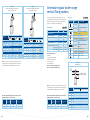
Plume management terminal positioning
External condensate pipe work
Insulate
& increase
pipe size
100mm dia.
±45°
Plume management deflector:
External
rain water
pipe into
foul water
Syphon
trap
External
air break
Air gap
Flue exhaust
outlet
8
Drainage
holes
Syphon
trap
180°
Air intake
12mm dia. 300mm
500mm min.
Pipe work
transition
All measurements in millimetres
100mm
dia. min.
plastic pipe
25mm
25mm
Insulate
& increase
pipe size
Pipe work
transition
7
±80°
3
50mm
25mm
200
25mm min.
300
2
1,200
Balcony
100mm
dia. min.
plastic
pipe
68mm dia. PVCu
strap on fitting
Condensate
pump
Limestone chippings
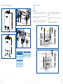
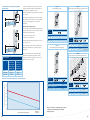
Fig. 4 Disposal into a rainwater down pipe
4
150
400mm
Drainage min.
holes
100
200
600
1
Bottom of sealed tube
200
200
25
300
150
Window
300
Window
300
200 5
Window
Door
Boundary
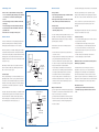
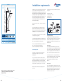
Fig. 6 Soak away
25
150
150
150
6
Drainpipe
Pipe work
transition
Syphon
trap
Pipe work
transition
Insulate
& increase
pipe size
Insulate
& increase
pipe size
Syphon
trap
Note
•
•
•
25mm min.
25mm min.
18
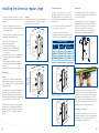
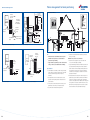
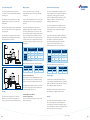
All measurements are the minimum clearances required.
Terminals must be positioned so to avoid combustion
products entering the building.
Support the flue at approximately one metre intervals and at
a change of direction, use suitable brackets and fittings.
1.
600mm distance to a boundary or surface facing a boundary,
unless it will cause a nuisance. BS 5440: Part 1 recommends
that care is taken when siting terminals in relation to
boundaries.
2.
Internal/external corners. The air intake clearance can be
reduced to 150mm providing the flue exhaust outlet has a
300mm clearance.
3.
The flue cannot be lower than 1,000mm from the top of the
light well due to the build up of combustion products.
4.
1,200mm between air intake and facing terminal.
Fig. 7 Condensate pump to external disposal
Clearance no less than 200mm from the lowest point of the
balcony or overhang.
Installations in car ports are not recommended.
6.
1,200mm from an opening in a car port on the same wall
i.e. door or window leading into dwelling.
7.
Using a Plume Management Kit the air intake measurement can
be reduced to 150mm providing the flue exhaust outlet has a
300mm clearance. Plume kits running horizontally must have a
10º fall back to the boiler for proper disposal of condensate.
For details on specific lengths see relevant boiler Technical &
Specification information.
8.
This feature allows some basic plume re-direction options on a
standard telescopic horizontal flue terminal. 300mm minimum
clearances to a opening e.g. window. However the minimum
clearance to an opening in direction that the plume management
is facing, must be increased to 1,500mm. Where the flue is less
than 150mm to a drain pipe and plume re-direction is used the
deflector should not be directed towards the drainpipe.
Key to illustration
Condensate
pump
Fig. 5 External disposal
5.
19