1
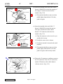
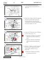
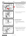
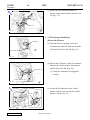
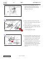
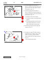
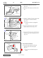
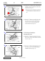
SCION
tC
2007 -
SECURITY (V5)
Preparation
NOTE: Part number of this accessory may not be
the same as the part number shown.
Part Number: PT398-21070
Kit Contents
Item #
1
2
Quantity Reqd.
1
1
Description
V5 Harness
GBS ECU
Quantity Reqd.
1
1
3
4
5
6
7
8
9
10
1
2
1
40
2
2
1
1
Description
V5 Security ECU
ECU Mounting Bracket
(For V5 ECU and GBS ECU)
Status Monitor
Bolts
Foam Tape Strip (1pcs)
Wire Ties
Splicing Connector
Warning Labels
Owner’s Manual
Warranty Card
Additional Items Required For Installation
Item #
Quantity Reqd.
Notes
Glass Cleaner
Household Windex
General Applicability
Hardware Bag Contents
Item #
1
2
Special Chemicals
Note: tC with factory keyless entry system, only.
Recommended Sequence of Application
Item #
1
2
3
4
Accessory
Security
Satellite Receiver
Audio
EC Mirror
*Mandatory
Vehicle Service Parts (may be required for reassembly)
Item #
1
2
3
Quantity Reqd.
Description
Description
Legend
Conflicts
STOP: Damage to the vehicle may occur. Do not
proceed until process has been complied with.
OPERATOR SAFETY: Use caution to avoid risk of
injury.
CAUTION: A process that must be carefully observed
in order to reduce the risk of damage to the
accessory/vehicle.
TOOLS & EQUIPMENT: Used in Figures calls out the
specific tools and equipment recommended for this
process.
Note: Do not install in vehicles with factory security
Recommended Tools
Personal & Vehicle
Protection
Notes
Safety Glasses
Safety Gloves
Vehicle Protection
Optional
Blankets, Part Boxes
Special Tools
Notes
Striker Tool (PPO only)
Wiring Terminal Tool (PPO
only)
CAD-E IADS P/N
ALL 02-016-01
CAD-E IADS P/N
ALL 02-016-03
Installation Tools
Notes
Screwdriver
Wrench
Socket
Nylon Panel Removal Tool
Phillips Head, #2
10 mm
10 mm
e.g. Panel Pry Tool #1
Toyota SST #00002-06001-01
Side Cutter
Screwdriver
Screwdriver
Torque Wrench
Pliers
Pick Tool
Issue: B
02/27/06
Flat Blade, Small
Jeweler’s
4.1N·m (36lbf·in)
Page 1 of 28 pages
SCION
tC
2007 -
SECURITY (V5)
Procedure
Care must be taken when installing this accessory to ensure damage does not occur to the vehicle. The installation of this
accessory should follow approved guidelines to ensure a quality installation.
These guidelines can be found in the "Accessory Installation Practices" document.
This document covers such items as:• Vehicle Protection (use of covers and blankets, cleaning chemicals, etc.).
• Safety (eye protection, rechecking torque procedure, etc.).
• Vehicle Disassembly/Reassembly (panel removal, part storage, etc.).
• Electrical Component Disassembly/Reassembly (battery disconnection, connector removal, etc.).
Please see your Toyota dealer for a copy of this document.
1. Vehicle Disassembly.
10 mm Wrench
Negative Battery Cable
Battery
(a) Take note of the battery cable installation
position, as this will need to be re-installed in
the same position after installation
completion.
(b) Remove the negative battery cable.
(Fig. 1-1)
(1) For vehicles equipped with automatic
transmission, place the shifter in the N
(neutral) position and set the parking
brake prior to disconnecting the battery.
Fig. 1-1
Nylon Panel Removal Tool
(2) Do not touch the positive terminal with
any tool when removing cable.
Fig. 1-2
Step Cover
(c) Remove the driver’s step cover. (Fig. 1-2)
(d) Remove the driver’s cowl cover. (Fig. 1-3)
Nylon Panel Removal Tool
(1) Remove the one nut securing the cowl
cover.
Cowl Cover
Nut
Fig. 1-3
Issue: B
02/27/06
Page 2 of 28 pages
SCION
tC
2007 -
SECURITY (V5)
Procedure
(e) Remove the fuse box cover. (Fig. 1-4)
Fuse Box Cover
(1) Take care not to damage the two upper
tabs.
Fig. 1-4
(f) Remove the cluster panel. (Fig. 1-5)
(1) Reach through the fuse box opening, then
push out the cluster panel from the
backside.
Knockout Cover
Fig. 1-5
(g) Remove the knockout cover in the cluster
panel, third space from the right. (Fig. 1-5)
Cluster Panel
(h) Remove two screws securing the lower
steering column cover behind the steering
wheel. (Fig. 1-6)
Phillips Screwdriver
(1) Insert the key into the ignition switch and
turn it to ON to unlock the steering
wheel.
Screw
Fig. 1-6
Steering Wheel
Screw
(2) Turn the steering wheel left and right to
gain access to the screws.
(i) Remove the lower steering column cover.
(Fig. 1-7)
Column Cover
Fig. 1-7
Issue: B
02/27/06
Page 3 of 28 pages
SCION
tC
2007 -
SECURITY (V5)
Procedure
Nylon Panel Removal Tool
FOR MANUAL TRANSMISSION MODELS ONLY.
(Step j)
(j) Remove the gearshift knob, then loosen the
console panel. (Fig. 1-8)
Gearshift Knob
Cigarette Lighter
Console Panel
(1) Do not remove the clip securing the
cigarette lighter harness.
Fig. 1-8
Nylon Panel Removal Tool
FOR AUTOMATIC TRANSMISSION MODELS
ONLY. (Step k)
(k) Loosen the console panel. (Fig. 1-9)
Console Panel
(1) Do not remove the clip securing the
cigarette lighter harness.
Fig. 1-9
(l) Lightly lift up the console panel, and then
turn the console panel clockwise as shown.
(Fig. 1-10)
Floor Console
Console Panel
(1) Cover the floor console with blanket
(protective sheet). (Fig. 1-11)
Fig. 1-10
Nylon Panel Removal Tool
Center Cluster Panel
(m) Remove the center cluster panel. (Fig. 1-11)
(1) Disconnect one (1) connector.
Console Panel
Protective
Sheet
Fig. 1-11
Issue: B
02/27/06
Page 4 of 28 pages
SCION
tC
2007 -
SECURITY (V5)
Procedure
(n) Remove the glove box under panel.
(Fig. 1-12)
Nylon Panel Removal Tool
Glove Box Under
Panel
Fig. 1-12
(o) Remove the passenger’s step cover.
(Fig. 1-13)
Nylon Panel Removal Tool
Step Cover
Fig. 1-13
Nylon Panel Removal Tool
Cowl Cover
(p) Remove the passenger’s cowl cover.
(Fig. 1-14)
(1) Remove the one nut securing the cowl
cover.
Nut
Fig. 1-14
Nylon Panel Removal Tool
(q) Remove the glove box assembly. (Fig. 1-15)
(1) Release the damper lever.
Glove Box
Damper Lever
Fig. 1-15
Issue: B
02/27/06
Page 5 of 28 pages
SCION
tC
2007 -
SECURITY (V5)
Procedure
2. V5 Wire Harness Installation.
(Steering Column Area)
(a) Locate and disconnect the white 8P
connector from the ignition switch area.
(Fig. 2-1)
8P (White)
Fig. 2-1
(b) Plug in the V5 harness’ white 8P connectors
between the vehicle harness’ 8P connector
and the ignition switch. (Fig. 2-2)
V5 Harness’ 8P
V5 Harness’
BLACK Wire
V5 Harness’ 8P
V5 Harness
Fig. 2-2
Vehicle Harness’ 8P
Side Cutter
Steering Column
Vehicle Clamp
V5 Harness
8P
White Tape
Fig. 2-3
Issue: B
(1) Verify the connectors are plugged in
securely.
Wire Tie
02/27/06
8P
Wire Tie
(c) Secure the V5 harness to the vehicle harness
with one wire tie. (Fig. 2-3)
(1) Ensure the wire tie is secured at the
vehicle clamp where the harnesses meet.
(d) Secure the 8P connectors (vehicle and V5
harness) to the V5 harness with one large
wire tie on the right side of the steering
column. (Fig. 2-3)
Page 6 of 28 pages
SCION
tC
2007 -
SECURITY (V5)
Procedure
Pliers, Side Cutter
4P (White)
FOR AUTOMATIC TRANSMISSION MODELS
ONLY. (Steps e – f)
Wire Side View
BLACK
4P
Splicing Connector
Wire Tie
V5 Harness
Fig. 2-4
(e) In the ignition switch area, locate the white
4P connector’s BLACK wire (top row, first
space from the left). Attach the V5 harness’
BLACK wire with a splicing connector.
(Fig. 2-4)
(1) Turn the connector so the wires face you
and the tab is on top.
(2) Verify the correct wire is chosen for
splicing.
(3) Verify the splicing connector is applied
properly.
(f) Route the V5 harness upward along the
steering column, then secure it to the vehicle
harness with one wire tie. (Fig. 2-4)
Pliers, Side Cutter
2P (White)
Splicing Connector
Wire Tie
FOR MANUAL TRANSMISSION MODELS ONLY.
(Steps g –h)
Wire Side View
2P
BLACK
V5 Harness
Fig. 2-5
(g) Locate in the ignition switch area the white
2P connector’s BLACK wire in the first
space from the left, and attach the V5
harness’ BLACK wire with a splicing
connector. (Fig. 2-5)
(1) Turn the connector so the wires face you
and the tab is on top.
(2) Verify the correct wire is chosen for
splicing.
(3) Verify the splicing connector is applied
properly.
(h) Route the V5 harness upward along the
steering column, then secure it to the vehicle
harness with one wire tie. (Fig. 2-5)
Issue: B
02/27/06
Page 7 of 28 pages
SCION
tC
2007 -
SECURITY (V5)
Procedure
(i) Loosely secure the V5 harness to the vehicle
harness with one wire tie below the steering
column. (Fig. 2-6)
Side Cutter
Wire Tie
V5 Harness
Fig. 2-6
(j) Locate and disconnect the white 17P
connector from the steering column area.
(Fig. 2-7)
17P
(White)
(k) Use a small jeweler’s screwdriver to lift up
the terminal retainer on the back of the 17P
connector. (Fig. 2-8)
Fig. 2-7
Jeweler’s Screwdriver,
Pick Tool (or Wiring Terminal Tool)
Retainer
(l) Locate the ORANGE wire in the top row,
first space from the left. Using a pick (or
wiring terminal tool (PPO)), release and pull
out the terminal for the ORANGE wire.
(Fig. 2-8)
17P
ORANGE
Vehicle Harness’
ORANGE Wire
Fig. 2-8
Wire Side View
(1) Turn the connector so the wires face you
and the tab is on top.
(2) Verify the correct wire is chosen.
Jeweler’s Screwdriver
V5 Harness
Retainer
1P (Female)
1P (Female)
Fig. 2-9
Issue: B
02/27/06
(m) Disconnect the empty 1P female connector
plugged into the V5 harness. Using a small
jeweler’s screwdriver, lift up the terminal
retainer on the back of the empty connector.
(Fig. 2-9)
(1) Do not pull out the retainer.
Page 8 of 28 pages
SCION
tC
2007 -
SECURITY (V5)
Procedure
Vehicle Harness’
ORANGE Wire
Terminal
Retainer
1P (Female)
Tab
17P
(1) The terminal should not come out when
pulled lightly from the back. If it does,
push it in again.
Vehicle Harness
Fig. 2-10
(o) Insert the terminal at the end of the V5
harness’ ORANGE wire into the top row,
first space from the left of the vehicle
harness’ 17P connector, then close the
retainer. (Fig. 2-11)
Retainer
Vehicle
Harness
17P
(1) Turn the connector so the wires face you
and the tab is on top.
V5 Harness’ ORANGE
Wire Terminal
17P
Fig. 2-11
(n) Insert the terminal at the end of the vehicle
harness’ ORANGE wire into the opening of
the empty 1P connector, then close the
retainer. (Fig. 2-10)
V5 Harness
Wire Side View
Side Cutter
Wire Tie
17P
V5 Harness
(2) Verify the correct wire is chosen.
(3) Verify the terminal is inserted and seated
properly.
(4) The terminal should not come out when
pulled lightly from the back. If it does,
push it in again, until securely seated.
(p) Plug in the 1P connectors, and then reconnect
the 17P connector. Secure the 1P connectors
and the V5 harness to the vehicle harness
with one wire tie. (Fig. 2-12)
1P
1P
Fig. 2-12
Issue: B
02/27/06
Page 9 of 28 pages
SCION
tC
2007 -
SECURITY (V5)
Procedure
(q) Locate and disconnect the black 12P
connector from the steering column area.
(Fig. 2-13)
12P (Black)
Fig. 2-13
V5 Harness’
12P (Black)
Side Cutter
Wire Tie
V5 Harness
(r) Plug in the V5 harness’ black 12P connectors
between the vehicle harness’ black 12P
connector and the steering column area.
Secure the wire tie previously installed below
the steering column. (Fig. 2-14)
V5 Harness’
12P (White)
Fig. 2-14
Vehicle Harness’
12P (Black)
12P
Side Cutter
Wire Tie
Vehicle Harness
12P
(1) Arrange the V5 harness' 12P connectors
on the right side of the V5 harness as
shown.
(2) Ensure the connectors do not interfere
with the steering column adjustment
lever.
V5 Harness
12P
Fig. 2-15
(s) Secure the 12P connectors to the V5 harness
with one wire tie. (Fig. 2-15)
Side Cutter
(t) Route the V5 harness toward the bottom of
the driver side J/B, then secure it to the
vehicle harness with three wire ties.
(Fig. 2-16)
V5 Harness’ Relay
V5 Harness
Wire Ties (x3)
(1) Route the V5 harness away from any
moving parts such as levers.
Fig. 2-16
Issue: B
02/27/06
Page 10 of 28 pages
SCION
tC
2007 -
SECURITY (V5)
Procedure
Side Cutter
Wire Tie
V5 Harness’
20P
V5 Harness
Wire Tie
Wire Tie
Hood
Opener
Cable
(u) Route the V5 harness toward the driver side
cowl area, then secure it to the vehicle
harness with three wire ties in the bottom of
the driver side J/B. (Fig. 2-17)
(1) Route the V5 harness between the
dashboard and the hood release cable.
Fig. 2-17
4P (Black)
Driver Side J/B
(v) Route the V5 harness to the driver side J/B
area as shown. (Fig. 2-18)
6P (White)
20P (White)
V5 Harness
Fig. 2-18
3. V5 Wire Harness Installation.
(Driver Side Cowl Area)
20P (White)
(a) Locate and disconnect the white 20P
connector from the driver side cowl area.
(Fig. 3-1)
Fig. 3-1
(b) Plug in the V5 harness’ white 20P connectors
between the vehicle harness’ 20P connector
and the driver side cowl area. (Fig. 3-2)
V5 Harness’ 20P
V5 Harness
Vehicle Harness’
20P
V5 Harness’ 20P
Fig. 3-2
Issue: B
(1) Verify the connectors are plugged in
securely.
02/27/06
Page 11 of 28 pages
SCION
tC
2007 -
SECURITY (V5)
Procedure
(c) Secure the 20P connectors and the V5
harness to the vehicle harness with one wire
tie. (Fig. 3-3)
V5 Harness
Side Cutter
20P
Wire Tie
Fig. 3-3
4. V5 Wire Harness Installation.
(Driver side J/B area)
6P (White)
(a) From the fuse box opening, locate and
disconnect the white 6P connector from the
left side of the driver side J/B. (Fig. 4-1)
Driver Side J/B
Fig. 4-1
V5 Harness’ 6P
V5 Harness’ 6P
(b) Plug in the V5 harness’ white 6P connectors
between the vehicle harness’ 6P connector
and the driver side J/B. (Fig. 4-2)
(1) Verify the connectors are plugged in
securely.
Vehicle Harness’ 6P
Fig. 4-2
Driver Side J/B
Side Cutter
V5 Harness’ 4P (Black)
(c) Secure the 6P connectors to the vehicle
harness with one wire tie, near the vehicle
harness’ clamp. (Fig. 4-3)
Wire Tie
6P
V5 Harness
6P
Fig. 4-3
Issue: B
02/27/06
Page 12 of 28 pages
SCION
tC
2007 -
SECURITY (V5)
Procedure
30P (White)
(d) From the fuse box opening, locate and
unlock the white 30P connector from the
upper left side of the driver side J/B, then
disconnect it. (Fig. 4-4)
Driver Side J/B
Fig. 4-4
Jeweler’s and Small Flat Screwdriver
Pick Tool (or Wiring Terminal Tool)
(e) Using a small flat screwdriver, lift up and
slide the 30P connector’s black lock cover to
remove it. (Fig. 4-5)
Connector Cover
30P
(f) Using a small jeweler’s screwdriver or pick
tool, lift the long terminal retainer on the 30P
connector. (Fig. 4-5)
30P
(1) Do not pull out the retainer.
Retainer
Fig. 4-5
Pick Tool (or Wiring Terminal Tool)
Vehicle Harness’
VIOLET Wire
30P
Wire Side View
VIOLET
Fig. 4-6
Issue: B
Vehicle Harness’
ORANGE Wire
02/27/06
30P
ORANGE
(g) Locate the VIOLET wire in the top row, nine
spaces from the left. Using a pick (or wiring
terminal tool (PPO)), release and pull out the
terminal for the VIOLET wire. (Fig. 4-6)
(h) Locate the ORANGE wire in the bottom row,
ten spaces from the left. Using a pick (or
wiring terminal tool (PPO)), release and pull
out the terminal for the ORANGE wire.
(Fig. 4-6)
Page 13 of 28 pages
SCION
tC
2007 -
SECURITY (V5)
Procedure
(i) Insert the terminal at the end of the V5
harness’ VIOLET wire into the top row, nine
spaces from the left of the vehicle’s harness
30P connector. (Fig. 4-7)
30P
V5 Harness’
VIOLET Wire
Terminal
Retainer
Wire Side View
VIOLET
30P
V5 Harness
Fig. 4-7
V5 Harness’ ORANGE ORANGE
Wire Terminal
(j) Insert the terminal at the end of the V5
harness’ ORANGE wire into the bottom row,
ten spaces from the left of the vehicle harness
30P connector. (Fig. 4-7)
(1) Verify the correct wire is chosen.
(2) Verify the terminal is inserted and seated
properly.
(3) The terminal should not come out when
pulled lightly from the back. If it does,
push it in again until securely seated.
(k) Close the long terminal retainer of the 30P
connector. (Fig. 4-7)
Jeweler’s Screwdriver
(l) Disconnect the empty 2P female connector
plugged into the V5 harness. Using a small
jeweler’s screwdriver, lift the terminal
retainer on the back of the empty connector.
(Fig. 4-8)
V5 Harness’ 2P
2P (Female)
Fig. 4-8
Issue: B
2P (Female)
02/27/06
Retainer
(1) Do not pull out the retainer.
Page 14 of 28 pages
SCION
tC
2007 -
SECURITY (V5)
Procedure
Vehicle Harness’
ORANGE Wire
Terminal
Retainer
Vehicle Harness’
VIOLET Wire
Terminal
(m) Insert the terminal at the end of the vehicle
harness’ VIOLET wire into empty 2P
connector’s left side opening. (Fig. 4-9)
2P (Female)
Wire Side View
2P
(1) Turn the connector so the wires face you
and the tab is on top.
ORANGE
VIOLET
Fig. 4-9
(n) Insert the terminal at the end of the vehicle
harness’ ORANGE wire into the empty 2P
connector’s right side opening. (Fig. 4-9)
(2) Verify the correct wire is chosen.
(3) Verify the terminal is inserted and seated
properly.
(4) The terminal should not come out when
pulled lightly from the back. If it does,
push it in again until securely seated.
(o) Close the retainer. (Fig. 4-9)
Jeweler’s Screwdriver
Retainer
V5 Harness’
YELLOW Wire
Terminal
30P
Wire Side View
30P
Fig. 4-10
V5 Harness
YELLOW
(p) Using a small jeweler’s screwdriver, lift the
center terminal retainer on the 30P
connector. Then insert the terminal at the end
of the V5 harness’ YELLOW wire into the
bottom row, seventh space from the left of
the vehicle harness’ 30P connector. (Fig. 410)
(1) Verify the correct wire is chosen.
(2) Verify the terminal is inserted and seated
properly.
(3) The terminal should not come out when
pulled lightly from the back. If it does,
push it in again until securely seated.
(q) Close the center terminal retainer of the 30P
connector. (Fig. 4-10)
Issue: B
02/27/06
Page 15 of 28 pages
SCION
tC
2007 -
SECURITY (V5)
Procedure
V5 Harness
Vehicle Harness
(r) Refit the 30P connector’s lock cover.
(Fig. 4-11)
(s) Reconnect 30P connector to the driver side
J/B.
Connector Cover
30P
Fig. 4-11
Side Cutter
(t) Plug the V5 harness’ 2P male connector into
the V5 harness’ 2P female connector.
(Fig. 4-12)
Wire Tie
V5 Harness
2P
Driver Side J/B
(u) Secure the 2P connectors to the vehicle
harness with one wire tie. (Fig. 4-12)
Vehicle Harness
Fig. 4-12
(1) Verify the connectors are plugged in
securely.
Side Cutter
Driver Side J/B
V5 Harness
Wire Tie
(v) Secure the V5 harness to the vehicle harness
behind the driver side J/B with one wire tie.
(Fig. 4-13)
Vehicle Harness
Fig. 4-13
Cluster Panel
5. Status Monitor Installation.
(a) Insert the status monitor into the open
knockout space of the cluster panel.
(Fig. 5-1)
Status Monitor
Fig. 5-1
Issue: B
02/27/06
(1) Ensure the correct knockout space is
chosen.
Page 16 of 28 pages
SCION
tC
2007 -
SECURITY (V5)
Procedure
V5 Harness
(b) Connect the V5 harness’ black 4P connector
to the status monitor 4P connector.
(Fig. 5-2)
V5 Harness’
Black 4P
(1) Verify the connectors are plugged in
securely.
(c) Refit the cluster panel. (Fig. 5-2)
Fig. 5-2
Cluster Panel
6. V5 Wire Harness Installation.
(From Steering Area to Center Console Area)
V5 Harness
(a) Route the V5 harness toward the center
console area. (Fig. 6-1)
Brace
V5 Harness
Fig. 6-1
Vehicle Harness
Side Cutter
Pliers
V5 Harness’
White Tape
V5 Harness
Wire Tie
Splicing Connector
Wire Side View
40P
Fig. 6-2
(1) Route the V5 harness through the
opening space in front of the driver side
brace as shown.
ORANGE
V5 Harness’ ORANGE Wire
40P
(b) In the center console area, locate the white
40P connector’s ORANGE wire (bottom
row, sixteenth space from the left). Attach
the V5 harness’ ORANGE wire with a
splicing connector. (Fig. 6-2)
(1) Turn the connector so the wires face you
and the tab is on top.
(2) Verify the correct wire is chosen for
splicing.
(3) Verify the splicing connector is applied
properly.
(c) Locate the tape on the vehicle harness’ 40P
connector wires, then match it with the V5
harness’ white taping. Secure the harnesses
with one wire tie at the taping. (Fig. 6-2)
Issue: B
02/27/06
Page 17 of 28 pages
SCION
tC
2007 -
SECURITY (V5)
Procedure
(d) Secure the V5 harness to the vehicle harness
with three wire ties in the driver side center
console area. (Fig. 6-3)
Side Cutter
(1) Do not secure the V5 harness to the 10P
and 6P connectors’ harness with a wire
tie.
Wire Ties (x3)
V5 Harness
Fig. 6-3
Side Cutter
(e) Route the V5 harness toward the glove box
area, then secure it to the vehicle harness
with two wire ties in the passenger side
center console area. (Fig. 6-4)
Wire Ties (x2)
V5 Harness
Fig. 6-4
Side Cutter
7. V5 Wire Harness Installation.
(Passenger Side Area)
V5 Harness
Wire Ties (x5)
(a) Route the V5 harness to the glove box area,
then secure it to the vehicle harness with five
wire ties. (Fig. 7-1)
Fig. 7-1
Side Cutter
V5 Harness
(b) Route the V5 harness through the glove box
area, then secure it to the vehicle harness
with three wire ties. (Fig. 7-2)
Wire Ties (x3)
Fig. 7-2
Issue: B
02/27/06
Page 18 of 28 pages
SCION
tC
2007 -
SECURITY (V5)
Procedure
(c) Locate the vehicle harness’ white 1P
connector above the passenger side cowl
area. The plug the V5 harness’ white 1P
female connector into the vehicle harness’
white 1P male connector. (Fig. 7-3)
Side Cutter
Wire Ties (x2)
V5 Harness
V5 Harness’ Female 1P
Fig. 7-3
Vehicle Harness’ Male 1P
20P (White)
(1) If the 10P connector harness is secured to
the vehicle harness with breakaway tape,
then cut the breakaway tape.
Fig. 7-4
(g) Plug in the V5 harness’ white 10P connectors
between the vehicle harness’ 10P connector
and the passenger side cowl area. (Fig. 7-5)
V5 Harness
20P
Fig. 7-5
(1) Verify the connectors are plugged in
securely.
10P
(h) Plug in the V5 harness’ white 20P connectors
between the vehicle harness’ 20P connector
and the passenger side cowl area. (Fig. 7-5)
40P
(1) Verify the connectors are plugged in
securely.
Side Cutter
10P
V5 Harness
Wire Tie
20P
8P
(i) Secure the V5 harness’ 10P and 20P
connectors to the vehicle harness with one
wire tie. (Fig. 7-6)
40P
Fig. 7-6
Issue: B
(e) Secure the 1P connector and V5 harness to
the vehicle harness with one wire tie.
(Fig. 7-3)
(f) Locate and disconnect the white 10P and
white 20P connectors from the passenger
side cowl area. (Fig. 7-4)
10P (White)
8P
(d) Secure the V5 harness to the vehicle harness
with one wire tie. (Fig. 7-3)
02/27/06
Page 19 of 28 pages
SCION
tC
2007 -
SECURITY (V5)
Procedure
Small Flat Blade Screwdriver
8. V5 ECU, GBS ECU Preparation and
Installation.
GBS Setting
(a) Turn the adjustment screw on the GBS ECU
to the “6” position. (Fig. 8-1)
GBS ECU
Fig. 8-1
(b) Attach one foam tape to the GBS ECU.
(Fig. 8-2)
Foam Tape
GBS ECU
Fig. 8-2
V5 ECU
Connectors
Fig. 8-3
ECU
Mounting
Bracket
GBS ECU
(c) Insert the ECU mounting bracket into the
indicated bracket slot on the V5 ECU and the
indicated bracket slot on the GBS ECU.
(Fig. 8-3)
(1) Insert the mounting bracket into the
correct ECU slot; you have only one
chance to install it properly.
(2) Ensure the bracket is firmly attached to
each ECU.
Issue: B
02/27/06
Page 20 of 28 pages
SCION
tC
2007 -
SECURITY (V5)
Procedure
10mm Socket, Side Cutter
Brace
Bolts (x2)
(d) Connect the V5 harness’ 40P connector to
the V5 ECU and 8P connector to the GBS
ECU.
(e) Locate the two holes in the brace to the right
side of the glove box area. Secure the V5
ECU and GBS ECU to the outside of the
brace with two bolts supplied in kit.
(Fig. 8-4)
V5 ECU and GBS
V5 Harness
Wire Tie
Fig. 8-4
(1) Verify the bolts are tightened and
secured.
(f) Locate the V5 harness’ black taping, and the
white and gray connectors harness’ black
taping in the right side of the glove box area.
Match those tapings and secure with one
wire tie. (Fig. 8-4)
Warning Label
Line up with bottom
of window etching
10mm
9. Warning Label Installation.
(a) Clean the inside surface of the front door’s
windows. (Fig. 9-1)
(b) Place the warning label on the inside surface
of the front door’s windows as shown.
(Fig. 9-1)
Fig. 9-1
(1) Use a piece of clean adhesive tape to lift
the labels off their protective backing
sheet.
(2) Do not touch the adhesive surface of the
warning labels.
Issue: B
02/27/06
Page 21 of 28 pages
SCION
tC
2007 -
SECURITY (V5)
Procedure
Torque Wrench, 10 mm Socket
10. Completing the Installation.
(a) Complete the vehicle reassembly.
Negative
Battery
Cable
(1) Reconnect any disconnected connectors.
Battery
(2) Verify the panels fit together properly
with no uneven gaps between them.
(b) Clean up and remove any trash.
Fig. 10-1
Battery
(c) Reconnect the vehicle’s negative battery
cable. (Fig. 10-1)
(1) Position the negative terminal at an angle
of ~90° to the battery as shown.
(2) Tighten the nut with 4.1N·m (36lbf·in) of
torque.
(3) Be careful not to touch the positive
battery terminal.
(d) Reset the power windows.
(1) Turn ignition key to ON position.
(2) Push down the power window switches
of each door, and lower the windows
halfway.
(3) Pull up the switches until the windows
close and hold switches up for a further
one (1) second (minimum.)
(e) Reset the power moon roof.
(1) Push and hold moon roof switch to close
side until moon roof closes. Hold for a
further two (2) seconds.
(f) Reset the tailgate door.
(1) Push door lock control switch to the
“unlock” side.
(2) Pull up tailgate door handle.
(g) Place the owner’s manual, and warranty card,
left in their protective bags, in the glove box.
Issue: B
02/27/06
Page 22 of 28 pages
SCION
tC
2007 -
SECURITY (V5)
Checklist - these points MUST be checked to ensure a quality installation.
Check:
Look For:
Accessory Function Checks
Fit appropriate fuse before beginning.
Press and release the remote control’s lock
1. The turn signal lights flash once.
button to start the system’s arming process.
All doors lock.
The Status Monitor’s LED lights up.
Wait 30 seconds.
2. After 30 seconds, the LED starts flashing;
the system is now armed.
Press and release the remote control’s
3. The turn signal lights flash twice.
unlock button to disarm the system.
The driver’s door unlocks.
The LED stops flashing.
Open the driver’s door, insert the key
into the ignition switch and turn it to
“ON”. Roll down all the windows,
remove the key and exit the vehicle.
Arm and disarm the system with the remote
4. The doors automatically relock.
again, then wait 30 seconds.
The system automatically starts the arming
process.
Press and release the remote control’s
5. Refer to step # 3.
unlock button again to stop the arming
process.
Insert the key into the driver’s door key
6. All doors lock.
cylinder and turn it toward the front of the
The LED lights up.
vehicle to start the arming process.
Wait 30 seconds.
7. After 30 seconds, the LED starts flashing;
the system is now armed.
Issue: B
02/27/06
Page 23 of 28 pages
SCION
tC
2007 -
SECURITY (V5)
Checklist - these points MUST be checked to ensure a quality installation.
Check:
Look For:
Reach inside and manually unlock the
8. The driver’s door automatically relocks.
driver’s door to trigger an alarm.
The horn sounds repeatedly.
The headlights flash repeatedly.
The turn signal lights flash repeatedly.
The LED lights up.
Manually unlock the driver’s door again
9. The driver’s door lock attempts to lock
and hold it unlocked, open the door, then sit
repeatedly.
in the driver’s seat.
The horn continues to sound repeatedly.
The headlights and turn signal lights
continue flashing.
The LED remains on.
Insert the key into the ignition switch and
10. The horn stops sounding.
turn it to “START” to stop the alarm.
All the lights stop flashing and/ or turn off.
The LED turns off.
The starter cranks and the engine starts.
Turn the key back to “LOCK”, remove
it, and then exit the vehicle.
With the door open, press the lock switch
11. All doors lock.
on the door to lock the doors, then close the
The LED lights up.
door to start the system’s arming process.
Wait 30 seconds.
12. After 30 seconds, the LED starts flashing;
the system is now armed.
Reach inside and manually unlock the front
13. The front passenger’s door automatically
passenger’s door to trigger an alarm.
relocks.
The horn sounds repeatedly.
The headlights flash repeatedly.
The turn signal lights flash repeatedly.
The LED lights up.
Issue: B
02/27/06
Page 24 of 28 pages
SCION
tC
2007 -
SECURITY (V5)
Checklist - these points MUST be checked to ensure a quality installation.
Check:
Look For:
Press and release the remote control’s
14. The horn stops sounding.
unlock button to stop the alarm.
All the lights stop flashing.
The LED turns off
Press and release the remote control’s lock
15. Refer to step #1 and #2.
button to start the system’s arming process,
then wait 30 seconds until the system is
armed.
Roll up all windows, remove the key and
exit the vehicle.
Press and release the remote control’s lock
16. Refer to step # 1.
button to start the arming process.
Wait 30 seconds.
17. After 30 seconds, the LED starts flashing;
the system is now armed.
Perform the following check in a
temperature-controlled environment
(50° - 90° F.)
With the tip of key (or Striker Tool pulled
18. The horn sounds repeatedly.
all way out (PPO only)), tap the center of
The headlights flash repeatedly.
the driver’s door window to trigger the
The turn signal lights flash repeatedly.
“warn away” alarm.
The LED lights up.
NOTE: Adjust as necessary by increasing
the GBS setting to the next level if the
alarm does not trigger during the functional
verifications.
NOTE: If you do not disarm the system,
the alarm will last 20 seconds. It is not
necessary to check the alarm duration.
Issue: B
02/27/06
Page 25 of 28 pages
SCION
tC
2007 -
SECURITY (V5)
Checklist - these points MUST be checked to ensure a quality installation.
Check:
Look For:
Insert the key into the driver’s door key
19. The horn stops sounding.
cylinder and turn it toward the back of the
All the lights stop flashing and/ or turn off.
vehicle to stop the alarm
The status monitor’s LED turns off
Vehicle Function Checks
Head Lights
Functioning Head Lights
High Beams
Functioning High Beams
Turn Signal Lights
Functioning Turn Signal Lights
Tail Lights
Functioning Tail Lights
Stop Lights
Functioning Stop Lights
Backup Lights
Functioning Backup Lights
Hazard Lights
Functioning Hazard Lights
Marker Lights
Functioning Marker Lights
Dome/Courtesy Lights
Functioning Dome/Courtesy Lights
Panel/Switch Illumination
Accessory Controls/Illumination (if
Functioning Accessory
equipped)
Issue: B
Key Sensor Buzzer
Functioning Key Sensor
Fog Lights (if equipped)
Functioning Fog Lights
Daytime Running Lights (if equipped)
Functioning DR Lights
Trunk/Tailgate/Bed Lights (if equipped)
Functioning Lights
Glove Box Light (if equipped)
Functioning Glove Box Light
Cruise Control Light (if equipped)
Functioning Cruise Control Light
02/27/06
Page 26 of 28 pages
SCION
tC
2007 -
SECURITY (V5)
Checklist - these points MUST be checked to ensure a quality installation.
Check:
Look For:
Seat Belt Warning Light
Functioning Seatbelt Warning Light. If the
warning light remains "ON", it may
indicate a system malfunction.
Air Bag Warning Light
Functioning Air Bag Warning Light. If the
warning light remains "ON", it may
indicate a system malfunction
ABS Light (if equipped)
Functioning ABS Light. If the warning light
remains "ON,” it may indicate a system
malfunction.
Lamp Failure Sensor (if equipped)
Functioning Lamp Failure Light. If the
warning light remains “ON,” it may
indicate a system malfunction.
Track/Skid Control Light (if equipped)
Functional Track/VSC Light. If the warning
light remains “ON”, it may indicate a
system malfunction.
Issue: B
HVAC
All HVAC Controls Function
Power Locks (if equipped)
Functioning Power Locks
Power Windows (if equipped)
Functioning Power Windows
Power Seats (if equipped)
Functioning Power Seats
Power Sunroof (if equipped)
Functioning Sunroof
Horn
Functioning Horn
Gauges
Functioning Gauges
Front Wiper/Washer
Functioning Front Wiper/Washer
Rear Wiper/Washer (if equipped)
Functioning Rear Wiper/Washer
Clock (if equipped)
Functioning Clock
Accessory Power Socket (if equipped)
Functioning Power Socket
02/27/06
Page 27 of 28 pages
SCION
tC
2007 -
SECURITY (V5)
Checklist - these points MUST be checked to ensure a quality installation.
Check:
Look For:
Starter
Functioning Starter
Audio/Video (if equipped)
Functioning Audio/Video
Power Sliding Door (if equipped)
Functioning Power Sliding Door
Convenience Memory Settings (if
Functioning Memory Settings
equipped)
Heated Seats (if equipped)
Functioning Heated Seats
Massage Seats (if equipped)
Functioning Massage Seats
Rear Window Defogger (if equipped)
Functioning Rear Window Defogger
Power Side Mirrors (if equipped)
Functioning Power Side Mirrors
Side Mirror Defogger (if equipped)
Functioning Side Mirror Defogger
Front Windshield Defogger (if equipped)
Functioning Front Windshield Defogger
Navigation System (if equipped)
Functioning Navigation System
Power Back Door (if equipped)
Functioning Power Back Door
Audio Steering Wheel Controls (if
Functioning Audio Steering Wheel
equipped)
Controls
Remove the appropriate fuse after
checks are completed.
Issue: B
02/27/06
Page 28 of 28 pages