1
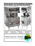
CECILWARE
COFFEE BREWERS
OPERATION MANUAL
MODEL NO.
GENERAL SPECIFICATIONS
ELECTRICAL DATA
Width
Depth
Height
Ship Wt.
(Ibs.)
Watts
Volts
Amps
CS2
16"
10"
203/4"
25
1600
2200
120
220
15
10
CS3
16"
10"
213/4"
26
1700
2300
120
220
15
10.5
CS2A, 2AWT
16"
10"
203/4"
27
1600
2200
120
220
15
10
CS3A, 3AWT
16"
10"
213/4"
28
1700
2300
120
220
15
10.5
CECILWARE CORPORATION
43-05 20th Avenue, Long Island City, NY 11105 • (718) 932-1414 • Fax (718) 932-7860
N257A 3/00
WARNING; MACHINE WARRANTY IS VOID IF MACHINE IS CONNECTED TO ANY VOLTAGE OTHER THAN
120 VOLTS. (EXPORT UNITS SHOULD BE CONNECTED TO 220 VAC VOLTS).
**INSTALLATION INSTRUCTIONS**
NOTE: A SEPARATE CIRCUIT SHOULD BE SUPPLIED FOR EACH OF THESE BREWERS WITH A 15 AMP. CIRCUIT BREAKER
OR FUSE. CHECK LOCAL CODES FOR COMPLIANCE IN INSTALLATION.
CAUTION: DO NOT CONNECT BREWER TO POWER SOURCE UNTIL AFTER PRIMING. (INSTRUCTIONS BELOW).
WATER HOOK-UP (FOR AUTOMATIC BREWERS ONLY) - (CS2A. 3A. 2AWT. 3AWT)
Automatic Brewers should be hooked up by a plumber in compliance with local plumbing codes. The National Sanitation Foundation (NSF)
requires the following for an NSF approved hook-up:
1. A quick disconnect water connection or enough extra coiled tubing, (at least two times the depth of brewer) so that brewer can be moved
to clean underneath.
2. An approved flowback prevention device such as a double check value to be installed between brewer and water supply.
Your automatic coffee brewer was shipped with a water hook-up kit consisting of a strainer, length of 1/4" (outside diameter) copper tubing and
water valve fitting which connects to valve in rear of brewer. This fitting needs to be finger tightened only. Connect the open end of the strainer
to 1/4" O.D. tubing and a shut-off valve (supplied by others) leading to cold water supply. 20-120 PSI water pressure, required for proper
operation.
TO PRIME ALL BREWERS:
1. Remove sample filter pack from funnel and insert funnel back into machine.
2. Place an empty decanter on warmer plate directly under funnel.
3. Lift cover (1, Fig. 1, 2) and pour 3 decanters of cold water through the top opening at 3 minute intervals. After the third decanter is poured,
water will flow through spray head and funnel and fill decanter beneath.
4. Plug line cord into receptacle and turn on power switch. The power light will light, indicating power is applied to the tank heater. Wait
approximately 15 minutes for the water to reach brewing temperature, at which point the green light will light. You are now ready to brew
coffee.
NOTE: In high altitude locations (at least 5000 ft. above sea level) thermostat setting may have to be lowered to prevent boiling. Turn
thermostat stem at back of brewer slowly counter-clockwise until boiling stops.
THESE INSTRUCTIONS ARE FOR INITIAL PRIMING ONLY AND DO NOT HAVE TO BE REPEATED FOR
NORMAL OPERATION.
NOTE: If brewer is not to be used for an extended period, turn off power switch. This will prevent excessive
evaporation of the water reserve in the tank, (in models without water tap) and save on your electric bill.
BACK-UP SYSTEM (Automatic Models - CS2A. 3A. 2AWT. 3AWT
In case of solenoid or timer malfunction or water supply problems (clogged strainer), automatic models may be used as pourover units simply by
lifting cover.
AUXILIARY HOT WATER FAUCET (CS2AWT. CS3AWT)
Automatic Brewers feature a hot water faucet and a solid state water level control which automatically replenishes water used and maintains the
proper water level inside the holding tank at all times.
The solid state level control has a built-in secondary control timer which shuts down the brewer in case of a malfunctioning brew timer, level
control or solenoid. A red (LED) indicator light will signal that service is required. In such case, brewing of coffee can continue by use of back up
system (manual pourover) until problem is solved.
**BREWING INSTRUCTIONS**
AUTOMATIC MODELS (MODEL NO. CS2A. 3A. 2AWT. 3AWT):
1. Make sure power switch and green ready light are on. (Wait for green ready light to come on if necessary).
2. Place paper filter in brew funnel. Open pack of fine grind coffee (as recommended by your coffee supplier) and spread evenly
on filter paper.
3. Insert Brew funnel back into machine and place empty decanter under funnel.
4. Turn on warmer switch beneath decanter and press brew switch. Coffee will be ready in 3 1/2 minutes.
5. Adjust timer (if necessary to fill decanter to just below band on handle)—(refer to instructions for timer adjustment).
6. Remove grounds and filter as soon as coffee has dripped through. Never pour coffee back through spent grounds.
POUR-OVER MODELS (CS2 & CS3):
1. Follow steps 1, 2 and 3 above.
2. Fill decanter with cold water to just below band on handle, lift cover (1, Fig. 1, 2), and pour water through top of opening.
Place empty decanter under funnel.
3. Turn on warmer switch beneath decanter. Coffee will be ready in 3 1/2 minutes.
4. Remove grounds and filter as soon as coffee has dripped through. Never pour coffee back through spent grounds.
**CLEANING INSTRUCTIONS**
1. Wash brew funnel and decanter by hand as needed. Do not use dishwasher, which may cause decanter breakage.
2. Clean plastic and stainless steel surfaces whenever necessary with a damp sponge or cloth and mild soap;
rinse thoroughly and wipe dry. CAUTION: Avoid using strong cleaners which may adversely affect the plastic parts.
3. Remove stains on stainless steel parts with a SCOTCHBRITE pad: Never use steel wool, as it will mar the finish.
4. Remove and clean spray head (22, Fig. 1; 15, Fig. 2) once a week to prevent lime build-up and clogging.
FOR AUTHORIZED SERVICE PERSONNEL ONLY
**SERVICE INSTRUCTIONS**
HIGH TEMPERATURE SAFETY SHUTOFF-RED RESET BUTTON:
If unit runs dry due to extended periods of non-usage with the power on, safety shutoff will automatically turn off the heating element. To put the
brewer back in operation, refill the tank compartment with water (follow priming instructions), push the red reset button, on the back of the
machine, and wait for the water to heat. When the brew light comes on, the machine is ready to brew coffee.
NOTE: In hard water areas, lime deposits may have to be removed before operating brewer again after it has run dry. Follow
directions under "Cleaning Instructions" for deliming.
2
THERMOSTAT ADJUSTMENTS:
1. Remove hole plug (3, Fig. 1, 2) from the round hole on top of cover. Place a suitable thermometer in hole and immerse bulb approximately 4
inches.
2. If water temperature is less than 197° F (92° C) slowly turn thermostat slot stem, on back of brewer, clockwise until ready light goes out.
When temperature of water approaches 197° to 203° F (92° to 95° C) slowly turn thermostat stem counter-clockwise until the green ready
light comes on. If water temperature cannot be increased when thermostat shaft is turned fully clockwise, then proceed as follows:
Place a small screwdriver into the center of thermostat shaft. While observing green ready light and temperature on thermometer, hold shaft and
turn small adjustment screw in center counter-clockwise until green ready light goes out. When temperature of water approaches 197°-203° F
(92°-95°C), slowly turn screw clockwise until ready light comes on. Turning screw clockwise lowers temperature: counter-clockwise raises it.
After adjusting center screw, place nail polish or glyptol on screw to set in position.
NOTE: As a final check, measure water temperature at Spray Head (22, Fig. 1:15, Fig 2). Temperature should be 197° to 203° F (92° to 95° C).
TIMER ADJUSTMENTS (Automatic Models Only):
To increase volume of water, turn knob of timer (24, Fig. 1; 48, Fig. 2) clockwise. To decrease, turn knob counter-clockwise. Turn knob by small
increments.
NOTE: Timer must go through a complete cycle before another adjustment can be made. Timer cannot be adjusted once it has been initiated.
**TROUBLE SHOOTING GUIDE**
(For Qualified Service Persons Only)
CAUTION; DISCONNECT POWER BEFORE ATTEMPTING ANY ELECTRICAL REPAIRS.
PROBLEMS WITH WARMER ELEMENTS & SWITCHES:
If warmer plate (20, Fig. 1:17, Fig. 2) fails to heat, first check power source. If power source is okay, check if light on warmer switch (15, Fig. 1;
18, Fig. 2) Is lit when in the "I" position. If warmer switch is lit, replace warmer plate by unplugging brewer, removing the two hold down screws
on plate and withdrawing warmer plate from brewer. Replace with new warmer plate. If warmer switch does not light, replace it. To remove
warmer switch press each tab behind front plate of brewer down with screwdriver in turn. As each tab is pressed, pop that corner of warmer
switch out of the front of brewer. New switch snaps in from the front.
IF WATER FAILS TO HEAT:
1. If amber power light (39, Fig. 1, 2) and warmer switches do not come on, check power source. Replace fuse or reset circuit breaker if
necessary. If power is good, check brewer wiring for continuity and replace damaged wire(s).
2. If amber power light is on, follow priming instructions; then press reset button on back of brewer and wait
approximately 15 minutes for water to heat and green ready light to come on. If water still fails to heat, disconnect line cord and check out tank
heater, (27, Fig. 1; 41, Fig. 2), thermostat (33, Fig. 1; 24, Fig. 2) and high temperature safety shutoff (35, Fig. 1; 43, Fig. 2). Replace needed
parts.
MAINTENANCE ON AUTOMATICS (CS2A. 3A. 2AWT. 3AWT)
IF NO WATER COMES FROM SPRAY HEAD: Check in the following order:
1. Water Supply Line
4. Timer (24, Fig. 1; 48, Fig. 2)
2. Line Fuse or Circuit Breaker
5. Level control (all WT brewers with spigots)
3. Solenoid (37, Fig. 1; 28, Fig. 2)
TESTING SOLENOID AND TIMER (CS2A & CS3A):
Make sure brewer is properly primed. Turn on power switch; then press brew switch and hold for one minute. If solenoid buzzes and water flows
through spray head when brew switch is pressed and held, but stops when switch is released, timer is defective. Replace it. If no water flows
from spray head, and solenoid is inactive, first check brew switch and wiring to solenoid and replace or repair as necessary. If brew switch and
wiring are okay, solenoid is at fault.
COFFEE BREWERS WITH HOT WATER SPIGOT (CS2AWT & CS3AWT):
1. When hot water is drawn for purposes of making tea, decaffeinated coffee or instant soup it is automatically replenished by means of a water
level control built into the system. Proper water level inside the tank is maintained at all times.
2. The outstanding feature of this water level control is its unique "Safe-Guard" circuit w hich prevents possible flooding which may be caused by
electrical component failure (i.e. switches, timer, level control sensor or solenoid, see Trouble Shooting guide for diagnosis). Problems with
any of the components will also be visually indicated by the red (LED) light. To reset the safeguard system, simply shut the power switch OFF
and then turn on again. 3. If there is no water coming out from the spray head when brew switch is depressed or if water does not refill when
hot water is drawn, check the following:
A) If LED light is on at the front, shut off the power switch and turn on again. This will reset the level control and automatic refill cycle. If LED
light goes off and there is no auto refill, proceed as follows:
1. Disconnect power.
2. Disconnect red wire from solenoid and also disconnect red wire from liquid level control (Terminal "Timer" —2nd from right side) (46,
Fig. 1; 30, Fig. 2), and connect this wire to solenoid, then perform solenoid test described in "Testing Solenoid and Timer" after
reconnecting power.
4. Disconnect power. If system operates but does not refill automatically, proceed as follows:
Connect the wire back to original wiring. Remove one wire on "Probe" terminal of water level control (Top one on left side of control).
Reconnect power and turn on power switch. If solenoid activates, water level control is operating normally. If Solenoid fails to activate, the
water level control is probably defective. Check the wiring for proper connection & continuity.
3
4
FIGURE 1
COFFEE STATION
MODELS
CS3AWT (SHOWN)
ITEM #
CS
1/1
2/2
3/3
4/5/6/7/5
8/7
9/8
10/11/12/13/14/15/18
16/19
17/20
18/19/35
REPLACEMENT PARTS LIST FOR COFFEE STATION AND OCS BREWERS
ITEM#
DESCRIPTION
PART# MODELS
CS
DESCRIPTION
Lid Cover
R128A
20/17
Warmer Element Assy. 120V
Cover Chain
P238A
Warmer Element Assy. 220V
Thermometer Hole Plug
P221A
21/16
Element Mounting Screw
Stainless Cover 2
R321V CS2 Series
22/15
Spray Head—Plastic
Stainless Cover 3
R325V CS3 Series
23/14
Spray Head Nut
Inside Tank Cover
R123A All CS
24/48
Solid State Timer 120V
Plastic Cover Screw
P154A All CS
Solid State Timer 220V
Water Trough
R126A AIICS
25/42
Tank Heater Gasket
Spray Tube Assembly
H134A All Except WT
27/41
Tank Heater 120V/1400W
Spray Tube Assembly
H159A All WT
Tank Heater 220V/2000W
Spray Head Gasket
M121A
28/6
Thermostat Bulb Clip
Polysulfone Tank
R122A All CS Except WT
29/9
Safety Shutoff Bulb Clip
Polysulfone Tank
R122E All CS WT
30/46
Safety Shutoff Spacer
Top Box (Less Components) R323V All CS Except WT
31/45
Safety Shutoff Tinnerman
Top Box (Less Components) R337A All CS WT
32/47
Safety Shutoff Mtg. Screw
Label
N509A All CS
33/24
Thermostat
Brew Funnel Runner—Right U490A All CS
34/26
Solenoid Mounting Screw
Brew Funnel Runner—Left
U493A AIICS
35/43
Safety Shutoff (Hi Limit)
Runner Screws
P182A All CS
36/27
Solenoid Tinnerman
Warmer Switch
L155A
37/28
Solenoid 120V
Bottom Cover
R327A
Solenoid 220V
Rubber Foot
M134A
38/44
Solenoid Fill Tube
Foot Mounting Screw
P148A All CS
39/Power Warm Switch
Spacer, Warmer Dish
P205A
Power Switch
5
PART#
G097A
G098A
P139A
E026A
E007A
L265A
L265E
M075A
G046A
G111A
P143A
P142A
M104A
P088A
P030A
L025A
P235A
L111A
P228A
L298A
L308A
M191A
L286A
L155A
MODELS
All Automatics
All Automatics
All Automatics
All Automatics
All Automatics
All Automatics
All Automatics
CS3 Series
CS2 Series