1
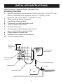
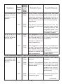
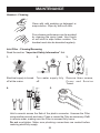
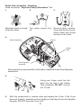
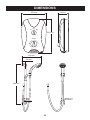
.8
kW
10
&
9.
5
8.
5,
Mira Play
ELECTRIC SHOWER
Installation & User Guide
These instructions are to be left with the user
1
Contents
Patents and Design Registration........................................................... 2
Introduction.............................................................................................. 3
Important Safety Information.................................................................. 4
Pack Contents Checklist......................................................................... 6
Specifications........................................................................................... 7
Installer Instructions................................................................................ 8
Plumbing Checklist................................................................................ 8
Electrical Checklist.............................................................................. 10
Installation.............................................................................................. 12
Mira Play............................................................................................. 12
Mira Response Adjustable Shower Fittings......................................... 14
Commissioning...................................................................................... 16
User Instructions.................................................................................... 18
Fault Diagnosis....................................................................................... 22
Maintenance............................................................................................ 26
Dimensions............................................................................................. 28
Wiring Diagram....................................................................................... 29
Spare Parts............................................................................................. 30
Mira Play............................................................................................. 30
Mira Response Shower Fittings.......................................................... 32
Accessories............................................................................................ 34
Notes....................................................................................................... 35
Customer Service................................................................................... 36
Patents and Design Registration
Design Registration:
000555768-0001
Patents:
GB:
2 237 860
Ireland:64471
If you experience any difficulty with the installation or operation of your new Electric
Shower, please refer to ‘Fault Diagnosis’, before contacting Kohler Mira Ltd. Our
telephone and fax numbers can be found on the back cover of this guide.
2
Introduction
Thank you for purchasing a quality Mira product. To enjoy the full potential of your
new product, please take time to read this guide thoroughly. Having done so, keep
it handy for future reference.
The Mira Play is an electric shower with separate controls for power selection and
temperature/flow adjustment. A unique flow regulator stabilizes temperature changes
caused by water pressure fluctuations. These can result from taps being turned on
or off, or toilets being flushed. An individual light indicates “POWER ON”.
This shower comes complete with a set of Mira Response Adjustable Shower
Fittings.
Mira Play 8.5 kW- A 8.5 kW 240 V AC (7.8 kW 230 V AC) heater. Mira Play 9.5 kW- A 9.5 kW 240 V AC (8.7 kW 230 V AC) heater. Mira Play 10.8 kW- A 10.8 kW 240 V AC (9.9 kW 230 V AC) heater.
Guarantee
For domestic installations, Mira Showers guarantee the Mira Play against any
defect in materials or workmanship for a period of two years from the date of purchase
(shower fittings for one year).
For non-domestic installations, Mira Showers guarantee the Mira Play against
any defect in materials or workmanship for a period of one year from the date of
purchase.
For terms and conditions refer to section “Customer Services”.
Mira Response Adjustable Shower Fittings
An adjustable spray handset with three different spray actions (start, soothe and
force), supplied complete with flexible hose, clamp bracket assembly, slide bar,
supports, soap dish, and hose retaining ring. Available in white/chrome finish.
Recommended Usage
Domestic
ü
Light Commercial
ü
Heavy Commercial
û
Healthcare
û
3
Important Safety Information
Installation must be carried out in accordance with these instructions, and must be
conducted by designated, qualified and competent personnel.
1. Warning!
This shower can deliver scalding temperatures if not operated, installed
or maintained in accordance with the instructions, warnings and cautions
contained in this guide and on or inside the appliance.
If you require a thermostatic shower Mira produce a range which also limit the
maximum temperature, for more information our contact details can be found
on the back cover of this guide.
1.1. Products manufactured by us are safe and risk-free, provided that they are
installed, used and maintained in good working order, in accordance with our
instructions and recommendations.
1.2. Isolate the electrical and water supplies before commencing installation. The
electricity must be turned off at the mains and the appropriate circuit fuse
removed, if applicable.
1.3. Mains connections are exposed when the cover is removed.
1.4. Refer to the wiring diagram before making any electrical connections (refer to
the wiring diagram at the back of this guide).
1.5. Make sure that any pipework that could become frozen is properly insulated.
1.6. Having completed the installation, make sure that the user is familiar with the
operation of the appliance.
1.7. Make sure that this guide is left with the user.
1.8. DO NOT commission this appliance if water leaks from the unit or the heater
tank pressure relief valve.
1.9. DO NOT fit any form of outlet control (e.g. Trigger handset) as the outlet acts
as a vent for the tank body. Only Mira recommended outlet fittings should be
used.
1.10.Make sure all electrical connections are tight, to prevent overheating.
1.11.Warning! DO NOT operate this appliance if it is frozen. Allow the appliance to
thaw before using. The shower unit must not be fitted where it may be exposed
to freezing conditions.
1.12.This product is not suitable for areas with high humidity (i.e steam rooms).
Please consult your installer.
1.13.THIS APPLIANCE MUST BE EARTHED. MAKE SURE SUPPLEMENTARY
BONDING COMPLIES WITH THE “REQUIREMENTS FOR ELECTRICAL
INSTALLATIONS”.
The installation must be in accordance with the current edition of ’The Plugs
and Sockets etc. (Safety) Regulations’ in force at the time of installation, this
Mira Play is intended to be permanently connected to the fixed electrical wiring
of the mains system.
4
2. Caution!
2.1. Read all of these instructions and retain this guide for later use.
2.2. The electrical installation must comply to “BS 7671 - Requirements for Electrical
Installations”, commonly referred to as the IEE Wiring Regulations - Part 7, or
any particular regulations and practices, specified by the local electricity supply
company.
2.3. The plumbing installation must comply with the requirements of UK Water
Regulations/Bye-laws (Scotland), Building Regulations or any particular
regulations and practices, specified by the local water company or water
undertakers.
2.4. Make sure that you fully understand how to operate this shower and make sure
that it is properly maintained in accordance with the instructions given in this
manual.
2.5. Anyone who may have difficulty understanding or operating the controls of any
shower should be attended whilst showering. Particular consideration should
be given to:
2.5.1. The young.
2.5.2. The elderly.
2.5.3. The infirm.
2.5.4. The disabled.
2.5.5. Anyone who suffers from a medical condition that can result in temporary
incapacity (e.g. epilepsy or blackouts).
2.5.6. Anyone inexperienced in the correct operation of the controls.
2.6. Children should be supervised to ensure that they DO NOT play with the
appliance.
2.7. Sunburn or skin conditions can increase your sensitivity to hot water. Make
sure that you set the shower to a cooler temperature.
2.8. If any of the following conditions occur, isolate the electricity and water supplies
and refer to ”To contact us”, on the back page of this guide.
2.8.1. If the cover is not correctly fitted and water has entered the appliance
case.
2.8.2. If the case is damaged.
2.8.3. If the appliance begins to make an odd noise, smell or smoke.
2.8.4. If the appliance shows signs of a distinct change in performance,
indicating a need for maintenance.
2.8.5 DO NOT operate this appliance if water leaks from this appliance.
2.9. When this appliance has reached the end of its serviceable life, it should
be disposed of in a safe manner, in accordance with current local authority
recycling, or waste disposal policy.
5
Pack Contents Checklist
Tick the appropriate boxes to familiarize yourself with the part names and to
confirm that the parts are included.
Mira Play
1 x Mira Play Electric Shower
3 x Fixing Screws
3 x Wall Plugs
Documentation
1 x Installation Template
1 x Guarantee and Registration Card
6
Mira Response Adjustable Shower Fittings
2 x Slide
Bar End Caps
2 x Wall Plugs
1 x Handset
2 x Hose Seals
1 x Slide Bar
1 x Clamp
Bracket Assembly
1 x 1.25 m
Flexible Hose
1 x Soap Dish
1 x Hose Retaining Ring
2 x Slide Bar
End Supports
2 x Fixing Screws
Specifications
1. Plumbing
1.1. Minimum maintained inlet pressure:
8.5 kW, 9.5 kW = 70 kPa (0.7 bar) 10.8 kW = 100 kPa (1.0 bar)
1.2. Maximum static inlet pressure of 1000 kPa (10 bar).
1.3. Minimum static inlet pressure of 50 kPa (0.5 bar) to keep the inlet valve
closed.
2. Electrical
2.1. The Mira Play 8.5 kW and 9.5 kW requires a 40 Amp fuse.
2.2. The Mira Play 10.8 kW requires a 45 Amp fuse.
2.3. The terminal block will accept cable sizes up to 16 mm2.
2.4. The Mira Play is suitable for installation in zone 1 and is rated IP X4.
3. Standards and Approvals
3.1. The Mira Play complies with all relevant directives for CE marking.
7
Installer Instructions
Read the section “Important Safety Information” first.
Plumbing Checklist
1.
2.
3.
4.
5.
6.
7.
8.
9.
10.
Minimum maintained inlet pressure 8.5 kW and 9.5 kW = 70 kPa (0.7 bar).
Minimum maintained inlet pressure 10.8 kW = 100 kPa (1.0 bar).
Maximum static inlet pressure = 1000 kPa (10 bar).
Water treatment device (if required).
Free flowing isolating valve.
Positioned over water catchment area.
Fitted to finished wall surface.
No sharp hose kinks.
Fittings positioned with greater than 25 mm
gap or outlet double checkvalve fitted.
Supply pipework flushed clear.
Watertight inlet connection and fittings.
Cover secured correctly.
Minimum
200 mm from
ceiling.
Convenient height
for all the family.
Fixed to finished
wall surface.
Hose Retaining Ring
Isolating Valve
25 mm Min
Avoid sharp kinks
Bath
8
Shower Tray
Plumbing (checklist in detail)
1. The appliance is designed to operate with a minimum maintained inlet
pressure of 70 kPa (0.7 bar), for 8.5 kW and 9.5 kW and 100 kPa (1.0 bar)
for 10.8 kW up to a maximum static inlet pressure of 1000 kPa (10 bar).
2. When installed in very hard water areas (above 200 ppm temporary hardness)
your installer may advise the installation of a water treatment device, to reduce
the effects of limescale formation. Your local water company will be able to
advise the hardness of water in your area.
3. It is recommended that a non-restrictive (free flowing) isolating valve is fitted
as part of the cold water supply pipe to allow the complete maintenance of the
appliance. Do not use a valve with a loose washer plate (jumper) as this can
lead to the build up of static pressure.
4. The appliance is only suitable for installation within the shower area. It is fitted
with a pressure relief device and must be positioned over a water catchment
area with the controls at a convenient height for all users.
5. The appliance must be fitted onto a finished flat and even wall surface (this
wall surface should be tiled or suitably waterproofed). Do not fit the appliance
to the wall and tile up to the case. For safety requirements, an air gap must be
left behind the appliance.
6. Avoid layouts where the shower hose will be sharply kinked. This may reduce
the life of the hose.
7. A Hose Retaining Ring is supplied to prevent the handset from dropping below
the spill-over level of the bath or shower tray, which could lead to contamination
from back-siphoning. The supplied Hose Retaining Ring should meet the greater
majority of user requirements for shower installations with flexible outlet fittings.
However, there will be occasions where it will not provide a suitable solution. In
these instances an outlet double checkvalve, e.g. a Mira DCV-H, must be fitted.
This will increase the required supply pressure typically by 10 kPa (0.1 bar).
See section “Accessories”.
8. Supply pipework must be flushed to clear any debris before connecting to the
appliance.
9. To avoid damage to the case when soldered fittings are used, pre-solder the
pipework and fittings before connecting them to the inlet connector assembly.
Refrain from applying excessive force when making any connections. Always
provide mechanical support when making the plumbing connections.
10. The appliance is fitted with a plastic inlet compression assembly for connecting
to a 15 mm supply pipe from the top, bottom or back. Double checkvalves, fitted
in the inlet supply to the appliance, cause a pressure build-up, which could
exceed the maximum static inlet pressure and damage the appliance.
9
Read the section “Important Safety Information” first.
Electrical Checklist
1.
2.
3.
4.
5.
6.
7.
Electrical supply fuse and consumer unit are adequate for the product.
Shower unit is earthed.
The minimum required supply cable size must conform to BS 7671.
Double pole isolating switch.
DO NOT twist live or neutral cable cores.
Electrical connections are tightly secured.
DO NOT strain the terminal block.
Plumbing supply completed before electricity supply is turned on.
Consumer Unit
Double pole Isolating Switch
10
Electrical (checklist in detail)
1. In a domestic installation, the rating of the electricity supplier’s fuse and the
consumer unit must be adequate for the additional demand. All Mira Play electric
showers are high power units, therefore it is essential to contact your electricity
supplier to ensure that the supply is adequate for the product. Voltage drop due
to local heavy demand will reduce the shower’s performance.
2. The appliance must be earthed by connecting the supply cable’s earth
conductor to the earth terminal.
Supplementary bonding: Within the bathroom or shower room, all accessible
conductive parts of electrical equipment and extraneous conductive parts
(metal parts) that are likely to introduce earth potential, must be electrically
bonded to earth. If the cable is not mechanically protected, the cable size must
be a minimum of 4.0 mm² (2.5 mm² if mechanically protected). Use a suitable
earth bonding strap to connect the earth terminal to 15 mm copper pipe. The
installation must comply with the “Requirements for electrical Installations” in
accordance with BS 7671.
3. Supply cable - see opposite.
Important! The shower circuit should be separated from other circuits by at
least twice the diameter of the cable or conduit, and it should not be run through
thermally insulating material or in locations where the ambient temperature is
likely to exceed 30°C. If any of these conditions are unavoidable, it is necessary
to determine the cable size which will prevent damage to the cable caused by
overheating.
4. As a guide only, and in accordance with BS 7671 we recommend close circuit
protection: i.e. 9.5 kW = 40 Amp.
A 30 mA Residual Current Device (RCD) must be included in the electrical
circuit. This may be part of the consumer unit or a separate unit. A separate,
permanently connected supply is taken from the consumer unit to the appliance
through a double pole isolating switch, which has at least 3 mm of contact
separation. The switch can be a ceiling mounted pullcord type within the shower
room, or a wall mounted switch in an adjacent room.
5. DO NOT twist the individual cable cores of either the live or neutral conductors,
as this will prevent them from entering the terminal block.
6. DO NOT exert strain on the terminal block. Make sure that the electrical
connections are tightly screwed down.
7. DO NOT turn on the electrical supply until the plumbing has been completed.
11
Installation
Mira Play
Read the section “Important Safety Information” first.
1.
2.
Electrical supply is turned
off at the mains.
200 mm minimum gap
from ceiling.
Remove three screws.
4.
5.
6.
Remove Cover and
determine supply pipe
position.
For back inlet use soldered
elbow.
Caution! Do not drill into
buried cables or pipes.
7.
8.
9.
Fix appliance to wall.
Flush a minimum of 10
litres through pipework.
INSTALLATION
L
TEMPLATE
200 mm
3.
N
Mira Sport
Attention Installer
Drill and plug* the three
holes using template.
* Alternative fixings for some wall structures are not supplied.
12
10.
11.
Connect supply pipe. Do not
overtighten!
12.
Feed cable into Case. Fit Earth
sleeve (not supplied) and strip
insulation.
Do not twist cable cores.
13.
L = BROWN
= GREEN
N = BLUE
Firmly connect the conductors. Do
not exert strain on the terminal
block.
14.
Make sure wires are clear of all
mounting holes.
15.
Refit the Service Tunnel and Cover.
Make sure they fit correctly.
Do not overtighten screws.
13
Do not use alternative screws to
secure the Cover. This can cause
internal damage to the appliance.
Do not seal around the back of
appliance.
Mira Response Adjustable Shower Fittings
Read the section “Important Safety Information” first.
Clamp Bracket
1.
2.
Release
Button
Soap Dish/Hose
Retaining Ring
Slide Bar
25 mm Minimum
Spill-over level
Depress release button FULLY
and assemble Clamp Bracket.
Release the button when in desired
position.
Position as shown to prevent back
siphoning.
3.
4.
Slide the Soap Dish and the Hose
Retaining Ring onto the Slide Bar
below the Clamp Bracket.
Fit both the top and bottom Supports.
Make sure the slots are aligned to
fit fully home.
14
5.
6.
Caution! Do not drill into buried
cables or pipes.
Mark the positions of the slots on
both top and bottom Supports.
7.
8.
First fix bottom Slide Bar Support
and fully tighten the screw*. Then
fix the top Slide Bar Support whilst
pressing it down, to keep the whole
assembly together.
Fit the End Caps to the Slide Bar
Supports.
9.
Fit the Hose to both the Handset and the
Shower Outlet, remembering to pass it through
the Hose Retaining Ring. Do not overtighten
the Hose connections.
* Alternative fixings for some wall structures are not supplied.
15
Commissioning
If you are unsure how an electric shower works, please read through the section
“User Instructions” before continuing.
1.
2.
3.
Electrical supply is turned
off at the mains.
Set control to LOW.
Turn water supply fully
on.
4.
5.
6.
Check for water leaks.
Turn control to full cold.
Switch on electrical
supply.
7.
8.
9.
LD
CO
PUSH
0-5 secs
Push START button.
Water will be flowing at a
cool temperature.
Tu r n c o n t r o l s l o w l y.
Temperature remains cool
and flow is reduced.
10.
11.
12.
+
_
5-10 secs
Turn control to full cold.
Set control to MEDIUM.
16
The temperature will rise
slightly.
13.
14.
+
_
Set control to HIGH.
15.
The temperature will rise further.
16.
PUSH
Adjust temperatures as required.
Flow rate will adjust automatically.
Press STOP and isolate power.
17.
Residual water may drain over a
few minutes.
Note! A slight “hissing” sound may be heard from the appliance during operation.
High mains water pressure and high shower temperature will affect the tone. This
is quite normal in use.
17
User Instructions
How Your Electric Shower Works
Hot water is produced by passing
cold water through a heating tank.
+
LD
CO
_
The shower has three heater settings.
+
_
+
_
The warmer the shower, the lower
the flow rate and vice versa.
18
The Effect of Seasonal Changes
+
* **
_
For a cold shower select Low.
For a summer warm shower select Medium.
For a winter warm shower select High.
During extremes of mains water supply temperature, adjust heater setting to obtain
a better showering temperature.
The Effect of Other Water Devices
Example of how shower temperature stabilizes due
to sudden pressure changes.
+
Selected
Showering
Temperature
_
Showering temperature
will stabilize to within 6°C
band if other outlets are
opened whilst showering,
providing the minimum
pressure does not fall
below 70 kPa (0.7 bar).
Water inlet pressure fluctuations due to other draw offs (e.g. flushing toilet) will cause
the showering temperature to increase.
19
Using Your Shower
Read the section “Important Safety Information” first.
1.
2.
PUSH
Switch on electrical supply.
3.
Press START button.
4.
+
_
Set to desired position.
Check water temperature before
entering shower.
5.
+
_
Allow 10-15 seconds for any temperature adjustments to reach the
handset.
6.
7.
PUSH
Press STOP button and the shower
will shut down.
A small amount of water may
continue to drain over a few
minutes.
20
Changing the Spray Setting
The handset has three different spray settings (Start, Soothe and Force).
1.
2.
Start
Turn the Spray Plate anticlockwise
until it “clicks”. Water will flow from
the outer set of holes.
Soothe
Turn the Spray Plate anticlockwise
until it “clicks”. Water will flow from
the large diameter holes.
3.
Force
Turn the Spray Plate anticlockwise
until it “clicks”. Water will flow from
the inner set of holes.
Adjusting the Clamp Bracket
1.
2.
Depress the release button and
slide the Clamp Bracket assembly
to the required position.
Move the Handset to the required
angle.
21
Fault Diagnosis
The trouble shooting information table below gives details on probable causes and
remedies should difficulties be encountered whilst the shower is in operation.
Warning! There are no user serviceable components beneath the cover of the
appliance. Only a competent tradesperson should remove the front cover!
Symptom
Heater
Setting
Power
Low/
Light
Med/
High
Probable Cause
Possible Remedy
Shower is too
hot during the
summer.
ON
High
Incoming water is
warmer in the summer,
so the shower heater
setting is too high.
Turn heater control to
medium and adjust
temperature control until
the desired temperature
is achieved.
Shower is too
hot.
ON
Med/
High
Handset blocked.
Remove and clean.
Turning the
temperature
control does not
affect the water
temperature.
ON
Med/
High
Handset blocked.
Remove and clean. If
fault persists, contact
the shower installer.
Water continues to
flow when double
pole switch is
turned off.
OFF
Any
T h e d i a p h r a g m i s Contact shower installer
damaged.
to replace the flow valve
assembly.
No water or very
low flow rate.
OFF
ON
ON
OFF
Any
The power is off at the Switch on the power at
double pole switch.
the double pole switch.
Any
The incoming water Open the stop/isolating
supply stop valves, or valve fully.
the appliance isolating
valve, is closed.
Any
Handset blocked.
Remove and clean. For
sprayplate cleaning,
refer to the handset
manual.
Any
The fuse is blown or the
MCB/RCD has been
tripped, indicating a
possible electrical fault.
Renew the fuse or reset
the MCB/RCD. If the
fault persists, contact
the shower installer.
22
Symptom
No hot water from
shower, with the
controls in any
position.
S h o w e r
temperature
cycles between
hot and cold.
Heater
Setting
Power
Low/
Light
Med/
High
Probable Cause
Possible Remedy
Make sure the other
water outlets, such as
a washing machine or
dishwasher, are not in
use during showering.
ON
Med/
High
Other water outlets
are being used during
showering, causing the
water pressure to drop
below the minimum
requirement.
ON
Med/
High
The water pressure Make sure that the
is below the minimum incoming water supply
required.
isolating valve(s) are
completely open. If the
fault persists, contact
the shower installer.
ON
Med/
High
The temperature is set
too high. This is causing
the thermal switch to
turn off the heating
element to reduce the
water temperature.
Turn the temperature
control anticlockwise
to reduce the water
temperature.
ON
Med/
High
The temperature is set
too high. This is causing
the thermal switch to
turn off the heating
element to reduce the
water temperature.
Turn the temperature
control anticlockwise
to reduce the water
temperature.
Do not tamper with the
thermal switch.
All the following remedies must be performed by a competent tradesperson!
No hot water from
the shower, with
controls in any
position.
ON
Med/
High
Insufficient mains water Contact local water
pressure.
company.
ON
Med/
High
Failure of the pressure Check the continuity
switch, microswitch or of the switches, using
thermal switch.
a suitable continuity
measuring device.
Replace the switches
as necessary.
ON
Med/
High
I n t e r n a l w i r i n g Check the integrity of the
connection failed.
internal wiring.
(continued).....
23
Symptom
Heater
Setting
Power
Low/
Light
Med/
High
ON
ON
Probable Cause
Possible Remedy
Med/
High
One of the heater tank Replace the heater
elements has failed.
tank.
Med/
High
S w i t c h a s s e m b l y Replace the switch
diaphragm fault. Water assembly.
dripping from the unit.
Turning the
temperature
control does not
affect the water
temperature.
ON
Med/
High
The Flow Regulator is R e p l a c e t h e f l o w
faulty.
regulator.
ON
Med/
High
The Handset
blocked.
No water, or very
low flow rate.
ON
Any
Handset blocked.
ON
Any
The incoming water Open the stop/isolating
supply stop valves, or valve fully.
the appliance isolating
valve, is closed.
ON
Any
Insufficient mains water Check the integrity of the
pressure.
internal wiring.
ON
Any
T h e h e a t e r t a n k i s Replace the heater
excessively scaled.
tank.
ON
Any
The pilot valve is faulty.
Replace.
ON
Any
Inlet filter blocked.
Clean or renew. See
“Maintenance” section.
OFF
Any
The power is off at the Switch on the power at
double pole switch.
the double pole switch.
OFF
Any
The fuse is blown or the Renew the fuse or reset
MCB/RCD has been the MCB/RCD. Replace
tripped, indicating a the heater tank.
possible electrical fault.
For example, heater
tank element failure.
24
i s Remove and clean. If
fault persists, contact
Customer Services.
Remove and clean.
Symptom
Water leaks from
the bottom of the
case near the
outlet. There is
no flow from the
outlet.
The water cannot
be turned off.
Heater
Setting
Power
Low/
Light
Med/
High
ON
Any
Probable Cause
Possible Remedy
The pressure relief valve
in the heater tank has
been triggered (this
works to reduce the
damage to the appliance
if the outlet is blocked or
the unit is frozen.
When the relief valve
operates, a small rubber
ball is ejected.
Resolve the blocked
outlet.
Reset the Relief
Valve assembly. See
“Maintenance” section.
OFF
Any
T h e P i l o t Va l v e i s Replace.
faulty.
OFF
Any
T h e d i a p h r a g m i s Replace the flow Valve
damaged.
assembly.
OFF
Any
The supply pressure Contact local water
is below the minimum company.
requirement.
Check the static water
pressure. Note! The
static pressure may
fall below minimum
requirement when other
appliances are drawing
water. For example, a
washing machine or
garden hose.
25
Maintenance
Handset - Cleaning
Clean with mild washing up detergent or
soap solution. Wipe dry with soft cloth.
R
EA
CL
Poor shower performance can be avoided
by cleaning the spray head. Use thumb
or soft cloth to wipe rubber nozzles. The
handset must also be descaled regularly.
Inlet Filter - Cleaning/Renewing
Read the section “Important Safety Information” first.
1.
2.
3.
Electrical supply is turned
off at the mains.
Turn water supply fully
off.
Remove three screws,
Cover and Service
Tunnel.
4.
5.
Hold a wrench across the flats of the plastic connector. Unscrew the Filter
using another wrench as shown. Clean or renew the Filter as necessary. Refit
in reverse order, making sure the Filter is screwed fully home.
Do not overtighten. Make sure plumbing connections are sealed before
restoring electricity supply.
26
Relief Valve Assembly - Resetting
Read the section “Important Safety Information” first.
1.
2.
3.
Electrical supply is turned
off at the mains.
Turn water supply fully
off.
4.
Remove three screws,
Cover and Service Tunnel.
Small rubber ball should
be loose in the Case.
Screws
Switch Assembly
Heater
Tank
Flow Regulator
Assembly
Ball
Remove the five screws and lift out the Switch, Heater Tank and Flow Regulator
assemblies.
5.
Using your finger, push the ball
back into the hole in the Heater
Tank assembly. DO NOT remove
the ‘O’ seal.
Ball
6.
Refit the components in reverse order and replace the Cover. If the Cover
does not fit easily, rotate the controls slightly so that they fit onto the Spindles
beneath. DO NOT force the Cover to fit.
27
Dimensions
225 mm
98 mm
335 mm
332 mm
52 mm
600 mm
28
START/
STOP
Internal Wiring Diagram
Wiring Diagram
29
Spare Parts
Mira Play
406.27
416.38
439.75
439.76
439.77
439.88
439.89
439.90
439.92
439.93
439.94
439.99
1539.339
1539.340
1539.341
1539.342
1539.343
1539.344
1539.349
1539.350
1539.352
1539.355
Inlet filter (with ‘O’ Seal fitted)
Inlet Clamp Bracket
Inlet Connector Assembly
Clamp Bracket - components identified “A”
Flow Regulator Assembly 8.5kW
Seal Pack - components identified “B”
Screw Pack - components identified “C”
Thermal Switch
Heater Tank 8.5 kW
Heater Tank 9.5 kW
Heater Tank 10.8 kW
Outlet Connector and Ball
Switch Assembly
Neon Assembly (not shown)
Cover Assembly - White/White Panel
Cover Assembly - Satin/Chrome Panel
Service Tunnel - White
Service Tunnel - Satin
Terminal Block Assembly
Flow Regulator Assembly
Start/Stop Switch Assembly
Cover Assembly - White/Chrome Panel
30
C
1539.339
1539.349
439.90
439.92
439.93
439.94
A
C
B
C
1539.343
1539.344
A
406.27
439.75
C
B
1539.352
C
416.38
B
439.77
1539.350
439.99
C
B
C
1539.341
1539.342
1539.355
4 mm MINIMUM
Important Note! Push-fit connectors must be assembled back to back onto
terminals of micro‑switches.
A minimum air gap of 4 mm must be maintained between the connectors
after assembly.
31
Mira Response Shower Fittings
150.58
411.05
411.23
411.30
411.37
411.53
411.58
411.91
411.92
411.94
411.96
413.22
413.24
413.30
413.33
413.34
413.58
632.73
Hose - chrome
Adjuster Ring - white
Clamp Bracket Assembly - white
Slide Bar Support Assembly - white
Service Pack ‘O’ Seals - components identified ‘A’
Slide Bar - stainless steel
Hose Retaining Ring - white
Soap Dish Pack - white
Adjustable Handset - white
Screw Pack
Spray Plate Assembly - Low capacity
Adjuster Ring - satin chrome
Clamp Bracket Assembly - chrome
Slide Bar Support Assembly - chrome
Hose Retaining Ring - chrome
Soap Dish Pack - chrome
Adjustable Handset - chrome
Hose Washer
32
411.92
413.58
411.30
413.30
411.96
A
411.94
411.53
632.73
411 94
411.05
413.22
411.23
413.24
411.91
413.34
632.73
150.58
411.58
413.33
411.94
411.94
411.30
413.30
33
Accessories
Genuine Mira accessories can be purchased direct from Customers Services (our contact details can
be found on the back cover of this guide) or from approved stockists or merchants.
Everclear Showerhead
White - 2.1616.030
Chrome - 2.1616.031
Mira's new Everclear range has
been specially designed for hard
water areas and reduces the risk
of lime scale build up.
Showerhead Holder
White - 1.1540.270
Chrome - 1.1540.271
An alternative to the traditional
slide bar. Often a useful addition
when positioned for the smaller
members of the family.
Double Outlet Check Valve
(DCV-H)
Chrome - 1.0.110.55.1
DCV-H: An outlet double check
valve, designed to prevent the
backflow or backsiphonage of
potentially contaminated water,
through shower controls which
are fitted with a flexible hose as
part of the outlet shower fitting.
34
Shower Seat
White - 2.1536.128
White/Chrome - 2.1536.129
For use in or out of the
showering area. Note! Must be
installed onto a solid wall.
Shower seat folds up when not
in use
Notes
35
Customer Service
Guarantee
Your product has the benefit of our manufacturer’s
guarantee which starts from the date of purchase.
To activate this guarantee, please return your completed
registration card, visit our website or free phone 0800
0731248 within 30 days of purchase (UK only).
Within the guarantee period we will resolve defects in
materials or workmanship, free of charge, by repairing or
replacing parts or product as we may choose.
This guarantee is in addition to your statutory rights
and is subject to the following conditions:
● The product must be installed and maintained in
accordance with the instructions given in this user
guide.
● Servicing must only be undertaken by us or our
appointed representative. Note! if a service visit
is required the product must be fully installed and
connected to services.
● Repair under this guarantee does not extend the original
expiry date. The guarantee on any replacement parts
or product ends at the original expiry date.
● For shower fittings or consumable items we reserve
the right to supply replacement parts only.
The guarantee does not cover:
● Call out charges for non product faults (such as
damage or performance issues arising from incorrect
installation, improper use, lack of maintenance, build up
of limescale, frost damage, corrosion, system debris or
blocked filters) or where no fault has been found with
the product.
● Water or electrical supply, waste and isolation issues.
● Compensation for loss of use of the product or
consequential loss of any kind.
● Damage or defects caused if the product is repaired
or modified by persons not authorised by us or our
appointed representative.
● Routine maintenance or replacement parts to comply
with the requirements of the TMV 2 or TMV 3 healthcare
schemes.
Helpdesk Service
Our dedicated Customer Services Team is comprehensively
trained and can offer help and advice, spare parts,
accessories or a service visit. We will need you to have your
model name or number, power rating (if applicable) and date
of purchase. As part of our quality and training programme
calls may be recorded or monitored.
Mira Showers Website (www.mirashowers.co.uk)
From our website you can register your guarantee,
download additional user guides, diagnose faults, purchase
our full range of accessories and popular spares, refer to
our FAQ’s and request a service visit.
Spares and Accessories
We maintain extensive stocks of genuine spares and
accessories and aim to provide support throughout the
product’s expected life. Payment can be made by phone
at time of order using most major Credit or Debit cards and
we aim to despatch orders within two working days. Items
purchased from us are guaranteed for 12 months from date
of purchase. For safety reasons spares exposed to mains
voltages should only be fitted by competent persons.
Returns – items can be returned within one month of date of
purchase, providing that they are in good condition and the
packaging is unopened. Please obtain authorisation from
our Customer Services Team before return. We reserve the
right to apply a 15% restocking charge.
Service / Repairs
We have a nationwide team of Service Technicians who can
carry out all service or repair work to your product within the
guarantee period and beyond. You have the assurance of a
fully trained Mira Technician, genuine Mira spare parts and
a 12 month guarantee on any chargeable work done.
Payment should be made directly to the Service Technician
who will accept most major Credit or Debit cards.
To Contact Us
UK
Telephone: 0844 571 5000
Mon to Fri 8:00 am - 5:30 pm, Sat 8:30 am - 3:30 pm
E-mail: [email protected]
If your product does not function correctly when you first Fax: 01242 282595
use it, contact your installer to check that it is installed By Post: Mira Customer Services Dept, Cromwell Road,
and commissioned in accordance with the instructions in Cheltenham, Gloucestershire, GL52 5EP
this manual.
Should this not resolve the issue, contact our Customer Eire
Services Team who will offer you or your installer advice and Telephone: 01 459 1344
if applicable arrange for a Service Technician to call.
Mon to Fri 9:00 am - 5:00 pm
If the performance of your product declines, check in this E-mail: [email protected]
manual to see if simple home maintenance is required. If Fax: Dublin 01 459 2329
you require further assistance call our Customer Services
By Post: Modern Plant Ltd (Dublin),
Team.
Otter House, Naas Road, Clondalkin, Dublin 22
What to do if something goes wrong
Extended Guarantees
A selection of protection plans are available that
enable you to cover repair bills for the life of your policy
(excludes Eire). Ring 01922 471763 for more details.
Mira is a registered trade mark of
Kohler Mira Limited.
The company reserves the right to alter
product specifications without notice.
1058045-W2-E (J96K-R, J96Ya-d) (1539)
5+!3
36
© Kohler Mira Limited, September 2009