1
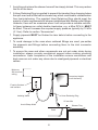
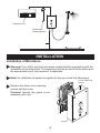
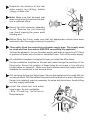
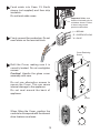
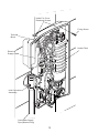
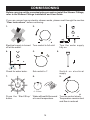
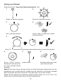
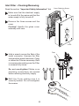
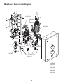
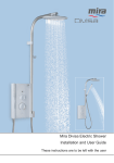
MIRA AZORA
ELECTRIC SHOWER
Installation and User Guide
These instructions are to be left with the user
1
CONTENTS
Patents and Design Registration............................................................ 2
Introduction.............................................................................................. 3
Guarantee.................................................................................................. 3
Important Safety Information.................................................................. 4
Pack Contents Checklist......................................................................... 6
Specifications........................................................................................... 7
1. Plumbing........................................................................................... 7
2. Electrical............................................................................................ 7
3. Standards and Approvals.................................................................. 7
Installation Requirements....................................................................... 7
1. Plumbing........................................................................................... 7
2. Electrical............................................................................................ 9
Installation.............................................................................................. 10
Installation of Mira Azora..................................................................... 10
Commissioning...................................................................................... 14
User Instructions.................................................................................... 16
Fault Diagnosis....................................................................................... 20
Maintenance............................................................................................ 22
Dimensions............................................................................................. 24
Spare Parts............................................................................................. 25
Wiring Diagram....................................................................................... 27
Customer Service................................................................................... 28
PATENTS AND DESIGN REGISTRATION
Design Registration:
000578463-001-002
Patents:
GB:
2 341 667, 2 404 000, 2 428 286
Ireland:82835, 85128, 85163
Patent Applications:
GB:
2 427 460
Ireland:2006/0462
If you experience any difficulty with the installation or operation of your new Electric
Shower, please refer to ‘Fault Diagnosis’, before contacting Kohler Mira Ltd.
Our telephone and fax numbers can be found in the back of this guide.
2
INTRODUCTION
Thank you for purchasing a quality Mira product. To enjoy the full potential of your
new product, please take time to read this guide thoroughly. Having done so, keep
it handy for future reference.
The Mira Azora is a thermostatic electric shower with separate controls for power
selection and temperature/flow adjustment. A unique thermostatic valve stabilises
temperature changes caused by water pressure fluctuations. These can result from
taps being turned on or off, or a toilet being flushed. An individual light indicates
“START/STOP”.
The Mira Azora comes complete with a set of Mira Energise Shower Fittings.
Mira Azora 9.8 kW
A 9.8 kW 240 V AC (9.0 kW 230 V AC) heater with Mira Energise adjustable spray
handset with four different spray actions (start, soothe, force and eco*). Supplied
complete with flexible hose, clamp bracket assembly, slide bar, supports, hose
retaining ring and soap dish. Available in the following finishes: frosted glass, blue
glass, grape glass, white flock, stripes, flag, stones and dots.
* The eco setting reduces the water flow to give economical use of water, whilst
still giving an adequate shower performance. This setting performs best with most
gravity, pumped, and mains pressure unvented systems. On electric showers and
some combination boiler systems the economy setting will have no effect, and will
give the same spray action as the start setting.
Recommended Usage
Domestic
ü
Light Commercial
ü
Heavy Commercial
û
Healthcare
û
GUARANTEE
For domestic installations, Mira Showers guarantee the Mira Azora 9.8kW against
any defect in materials or workmanship for a period of two years from the date of
purchase (shower fittings for one year).
For non-domestic installations, Mira Showers guarantee the Mira Azora 9.8kW
against any defect in materials or workmanship for a period of one year from the
date of purchase.
For terms and conditions refer to section “Customer Services”.
3
IMPORTANT SAFETY INFORMATION
Installation must be carried out in accordance with these instructions, and must be
conducted by designated, qualified and competent personnel.
Warnings!
Follow all warnings, cautions and instructions contained in this guide, and on or
inside the appliance.
1 Products manufactured by us are safe and risk-free, provided that they are
installed, used and maintained in good working order, in accordance with our
instructions and recommendations.
2. Isolate the electrical and water supplies before commencing installation. The
electricity must be turned off at the mains and the appropriate circuit fuse
removed, if applicable.
3. Mains connections are exposed when the cover is removed.
4. Refer to the wiring diagram before making any electrical connections (refer to
the wiring diagram at the back of this guide).
5. Make sure that any pipework that could become frozen is properly insulated.
6. Having completed the installation, make sure that the user is familiar with the
operation of the appliance.
7. Make sure that this guide is left with the user.
8. DO NOT commission this appliance if water leaks from the unit or the heater
tank pressure relief valve.
9. DO NOT fit any form of outlet control (e.g. Trigger handset) as the outlet acts
as a vent for the tank body. Only Mira recommended outlet fittings should be
used.
10. Make sure all electrical connections are tight, to prevent overheating.
11. The water supplies to this product must be isolated if the product is not to be
used for a long period of time. If the product or pipework is at risk of freezing
during this period they should also be drained of water.
12. Warning! DO NOT operate this appliance if it is frozen. Allow the appliance to
thaw before using. The shower unit must not be fitted where it may be exposed
to freezing conditions.
13. This product is not suitable for areas with high humidity (i.e steam rooms).
Please consult your installer.
14. THIS APPLIANCE MUST BE EARTHED. MAKE SURE SUPPLEMENTARY BONDING
COMPLIES WITH THE “REQUIREMENTS FOR ELECTRICAL INSTALLATIONS”.
The installation must be in accordance with the current edition of ’The Plugs
and Sockets etc. (Safety) Regulations’ in force at the time of installation, this
appliance is intended to be permanently connected to the fixed electrical wiring
of the mains system.
15. If the wiring layout is changed or amended, the product functionally and safety
may be affected.
4
16. If pipework and/or electical cables enter the shower from the rear through a
hole in the wall . Provision must be made to prevent water ingress back into
the wall structure.
17. If the shower is dismantled during installation or servicing then upon completion
the product must be inspected to ensure there are no leaks
18. DO NOT Position the handset to spray water directly on to the appliance.
Eg.When cleaning shower control.
Caution!
1.
2.
Read all of these instructions and retain this guide for later use.
The electrical installation must comply to “BS 7671 - Requirements for Electrical
Installations”, commonly referred to as the IEE Wiring Regulations - Part 7, or
any particular regulations and practices, specified by the local electricity supply
company.
3. The plumbing installation must comply with the requirements of UK Water
Regulations/Bye-laws (Scotland), Building Regulations or any particular
regulations and practices, specified by the local water company or water
undertakers.
4. Make sure that you fully understand how to operate this shower and make sure
that it is properly maintained in accordance with the instructions given in this
manual.
5. Anyone who may have difficulty understanding or operating the controls of any
shower should be attended whilst showering. Particular consideration should
be given to:
(a)
The young.
(b)
The elderly.
(c)
The infirm.
(d)
The disabled.
(e)
Anyone who suffers from a medical condition that can result in
temporary incapacity (e.g. epilepsy or blackouts).
(f)
Anyone inexperienced in the correct operation of the controls.
(g)
Children should be supervised to ensure that they do not play with the
appliance.
6. Sunburn or skin conditions can increase your sensitivity to hot water. Make
sure that you set the shower to a cooler temperature.
7. If any of the following conditions occur, isolate the electricity and water supplies
and refer to ”To contact us”, on the back page of this guide.
(a)
If the cover is not correctly fitted and water has entered the appliance
case.
(b)
If the case is damaged.
(c)
If the appliance begins to make an odd noise, smell or smoke.
5
(d)
If the appliance shows signs of a distinct change in performance,
indicating a need for maintenance.
(e)
DO NOT operate this appliance if water leaks from this appliance.
8. When this appliance has reached the end of its serviceable life, it should
be disposed of in a safe manner, in accordance with current local authority
recycling, or waste disposal policy.
PACK CONTENTS CHECKLIST
Tick the appropriate boxes to familiarise yourself with the part names and to
confirm that the parts are included.
Mira Azora
1 x Mira Azora
1 x Olive
1 x Compression Nut
3 x Fixing Screws
3 x Wall Plugs
Documentation
1 x Installation Template
1 x Installer Checklist
1 x Guarantee Card
6
SPECIFICATIONS
1. Plumbing
•
•
•
•
Minimum maintained inlet pressure 70 kPa (0.7 bar).
100 kPa (1.0 bar) recommended for satisfactory operation.
Maximum static inlet pressure 1000 kPa (10 bar).
Minimum static pressure 20 kPa (0.2 bar) to keep the inlet valve closed.
2. Electrical
•
•
•
The Mira Azora 9.8 kW requires a 45 Amp fuse.
The terminal block will accept cable up to 16 mm2 .
The Mira Azora is suitable for installation in Zone 1 and is rated IPX4.
3. Standards and Approvals
•
The Mira Azora complies with all relevant directives for CE marking.
INSTALLATION REQUIREMENTS
1. Plumbing
•
The appliance is designed to operate with a minimum maintained inlet pressure
of 0.7 bar up to a maximum static inlet pressure of 10 bar.
•
When installed in very hard water areas (above 200 ppm temporary hardness)
your installer may advise the installation of a water treatment device, to reduce
the effects of limescale formation. Your local water company will be able to
advise the hardness of water in your area.
•
It is recommended that a non-restrictive (free flowing) isolating valve is fitted in
the cold water supply pipe to allow the complete maintenance of the appliance.
Do not use a valve with a loose washer plate (jumper) as this can lead to a
build up of static pressures.
•
The appliance is suitable for installation within the shower area. It is fitted with
a pressure relief device and must be positioned over a water catchment area
with the controls at a convenient height for all users.
•
The appliance must be fitted on to a finished flat and even wall surface (this
wall surface should be tiled or waterproofed). DO NOT fit the appliance to
the wall and tile up to the case. For safety requirements, an air gap must be
left behind the appliance.
7
•
Avoid layouts where the shower hose will be sharply kinked. This may reduce
the life of the hose.
•
A Hose Retaining Ring is supplied to prevent the handset from dropping below
the spill-over level of the bath or shower tray, which could lead to contamination
from back-siphoning. The supplied Hose Retaining Ring should meet the
majority of user requirements for shower installations with flexible outlet fittings.
However, there will be occasions when it will not provide a suitable solution.
In these instances an outlet double checkvalve, e.g. a Mira DCV-H, MUST
be fitted. This will increase the required supply pressure typically by 10 kPa
(0.1 bar). Refer to section “Accessories”.
•
Supply pipework MUST be flushed to clear debris before connecting to the
appliance.
•
To avoid damage to the case when soldered fittings are used, pre-solder
the pipework and fittings before connecting them to the inlet connector
assembly.
•
To ensure the case and other components are not put under strain during
installation always provide mechanical support when making plumbing
connections. Upon completion of the installation ensure connections and
back case are not under any stress due to misaligned pipework or electrical
cables.
Minimum
200 mm from
ceiling
Convenient height
for all the family
Fixed to finished
wall surface
Hose Retaining Ring
Isolating Valve
25 mm Min
Avoid Sharp Kinks
Shower Tray
Bath
8
•
The appliance is fitted with a brass inlet compression assembly for connecting
to a 15 mm supply pipe from the top, bottom or back. Double checkvalves, if
fitted in the inlet supply to the appliance, can cause a pressure build-up, which
could exceed the maximum static inlet pressure and damage the appliance.
2. Electrical
•
In a domestic installation, the rating of the electricity supplier’s fuse and the
consumer unit must be adequate for the additional demand. All Mira electric
showers are high power units, it is essential to contact your electricity supplier
to ensure that the supply is adequate for the product.
•
Voltage drop due to local heavy demand will reduce the shower’s
performance.
•
The appliance MUST BE EARTHED by connecting the supply-cable earth
conductor to the earth terminal.
•
SUPPLEMENTARY BONDING: Within the bathroom or shower room, all
accessible conductive parts of electrical equipment and extraneous conductive
parts (metal parts) that are likely to introduce earth potential, must be
electrically bonded to earth using a minimum cable size of 4.0 mm² if the cable
is not mechanically protected, (2.5 mm² if mechanically protected).
•
The minimum cable size (cross-sectional area) required should be in
accordance with BS 7671.
•
As a guide only, and in accordance with BS 7671 we recommend close circuit
protection: i.e. 9.8 kW = 45 Amp
•
A 30 mA Residual Current Device (RCD) MUST be included in the electrical
circuit. This may be part of the consumer unit or a separate unit.
•
A separate, permanently connected supply must be taken from the consumer
unit to the appliance through a double-pole switch, which has at least 3 mm of
contact separation. The switch can be a ceiling mounted pullcord type within
the shower room, or a wall mounted switch in an adjacent room.
•
DO NOT twist the individual cable cores of either the live or neutral conductors,
as this will prevent them from entering the terminal block.
•
DO NOT exert strain on the terminal block. Ensure that the electrical
connections are tightly screwed down.
•
DO NOT turn-on the electrical supply until the plumbing has been
completed.
9
Consumer Unit
Double-pole
Isolating Switch
INSTALLATION
Installation of Mira Azora
Warning! Turn off the electrical and water supplies before proceeding with the
installation of the Mira Azora. The electricity must be turned off at the mains and
the appropriate circuit fuse removed, if applicable.
Note! An installation template is supplied to help you install the Mira Azora.
Cover Retaining
Screw
Remove the three cover retaining
screws and the cover.
Caution! Handle the glass cover
assembly with care.
Cover
10
Determine the direction of the inlet
water supply: top (falling), bottom
(rising), or back inlet .
Note! Make sure that the back inlet
does not go directly back into the wall.
Use a soldered elbow.
Swivel the inlet connector assembly
to suit. Remove the inlet blanking
cap. Avoid trapping the green earth
bonding wire.
Before fitting the Cover, make sure that the appropriate cutouts have been
removed to suit the supply entering the product.
Thoroughly flush the mains-fed cold water supply pipe. The supply must
be clean and free from debris BEFORE connecting the appliance.
To flush the pipework, turn on the water supply and drain a minimum of 10 litres
(2 gallons) of water into a bucket or catchment area. Turn off the water supply.
An installation template is supplied to help you install the Mira Azora.
Put the installation template on the wall and mark through the positions of the
fixing holes. Ensure the position of these holes do not come in line with any
buried cables or pipework. Make sure that sufficient electrical supply cable is
available for connection to the terminal block.
Drill and plug the top two fixing holes. Secure the appliance to the wall with the
screws provided. Drill the bottom fixing hole with the product in place. Alternative
fixings (not supplied) may be necessary for some wall structures. Avoid drilling
into any supply cable/pipe.
Install the mains-fed cold water
supply pipe. Do not overtighten
(See Plumbing Installation
Requirements).
11
Feed cable into Case. Fit Earth
sleeve (not supplied) and then strip
insulation.
Do not twist cable cores.
Important! Make sure
that the inlet earth wire is
routed as shown. Failure
to do so may cause
product malfunction.
L = BROWN
E = GREEN/YELLOW
Firmly connect the conductors. Do not
exert strain on the terminal block.
N = BLUE
Cover Retaining
Screw
Refit the Cover, making sure it is
correctly located. Do not overtighten
screws.
Caution! Handle the glass cover
assembly with care.
Do not use alternative screws to
secure the Cover. This can cause
internal damage to the appliance.
Do not seal around the back of
appliance.
Cover
When fitting the Cover, position the
controls to correspond with the internal
drive features as shown.
12
Holes For Cover
Retaining Screws
Fixing Screw
Terminal
Block
Heater Tank
Electrical
Supply Cable
Inlet Connector
Assembly
Cold Water Supply
Pipe (Bottom Entry)
13
COMMISSIONING
Before carrying out the commissioning procedure install the Shower Fittings,
refer to the Shower Fittings Installation and User Guide.
If you are unsure how an electric shower works, please read through the section
“User Instructions” before continuing.
1.
2.
3.
Electrical supply is turned
off at the mains.
Turn control to full cold.
Turn the water supply
fully on.
4.
5.
Check for water leaks.
Set control to ‘I’.
7.
8.
6.
Switch on electrical
supply.
9.
0 - 5 Secs
Press the ‘Start/Stop’
button.
Water will be at full force and
at a cool temperature.
14
Turn the control slowly.
Temperature remains cool
and flow is reduced
10.
11.
12.
+
_
0 - 10 Secs
Turn control to full cold.
Set control to ‘II’.
13.
14.
The temperature will rise
slightly.
+
_
5 - 10 Secs
Set control to ‘III’.
The temperature will rise further.
15.
16.
Adjust temperature as required.
Flow rate will adjust automatically.
Press STOP.
17.
18.
19.
0 - 5 Secs
Isolate power.
The shower will purge
water from its tank for a
few seconds.
Residual water may drain
over a few minutes.
Note! A slight hissing sound may be heard from the appliance during operation.
High mains water pressure and high shower temperatures will affect the tone. This
is quite normal in use.
15
USER INSTRUCTIONS
How Your Electric Shower Works
Heated water is produced by adjusting the flow
of cold water passed through a heater tank.
+
LD
CO
_
The shower has three heater settings.
+
_
+
_
The warmer the shower, the lower the flow
rate and vice versa.
16
Thermostatic (Temperature-Stable)
The shower's top priority is to keep the desired water temperature constant. Electric
showers with thermostatic control are able to keep a stable temperature across the
range from hot to cold, whilst also dealing with fluctuations in electrical and water
supplies. As a result, there is a temperature limit the shower cannot go beyond. For
safety, this temperature is factory set and cannot be adjusted to make the shower
hotter or colder.
ORDINARY
ELECTRIC
SHOWER
THERMOSTATIC
ELECTRIC
SHOWER
17
Using your Shower
Read the section “Important Safety Information” first.
1.
2.
Switch on electrical supply.
Press the ‘Start/Stop’ button.
3.
4.
+
_
Set to desired position.
Check water temperature before
entering shower.
5.
+
_
Allow 10 - 15 seconds for any temperature adjustments to reach the handset.
6.
7.
8.
P r e s s S TO P b u t t o n .
Shower will continue to run
for a few seconds before
stopping.
Isolate power.
Residual water may drain
over a few minutes.
Note! At the end of every shower make sure that the shower head points into the
catchment area. A small amount of water may be retained in the shower handset
after the shower has been turned off. This may drain over a few minutes.
Switch off the appliance at electrical isolating switch when not in use. This is for
safety and is recommended with all electrical appliances.
18
The Effect of Seasonal Changes
* **
+
_
For a cold shower select I.
For a summer warm shower select II.
For a winter warm shower select III.
During extremes of mains water supply temperature, adjust heater setting to obtain
a better showering temperature.
The Effect of Other Water Devices
Example of how shower temperature
stabilises due to pressure changes.
+
_
± 2°C
Water inlet pressure fluctuations due to other draw offs (e.g. flushing toilet). Shower
temperature will be controlled to within ± 2°C of the set temperature provided that
the supply conditions remain within the required operating parameters (refer to
section: ‘Specifications’).
19
FAULT DIAGNOSIS
The trouble shooting information tabled below gives details on probable causes and
remedies should difficulties be encountered whilst the shower is in operation.
Warning! There are no user serviceable components beneath the cover of the
appliance. Only a competent tradesperson should remove the front cover!
Symptom
Start/
Stop
Light
Heater
Setting
I/II/III
Probable Cause
Possible Remedy
Appliance Fails
to operate
OFF
Any
Electrical supply isolated at
double pole switch.
Switch on electrical supply via
the pullcord or wall mounted
switch.
OFF
Any
Fuse blown or MCB/RCD
tripped, indicating possible
electrical fault.
Renew the fuse or reset the
MCB/RCD. If fault persists,
contact your installer.
ON
II/III
Handset blocked.
Remove and clean.
ON
II/III
W a t e r p r e s s u r e b e l o w Make sure incoming mains
minimum required for appliance w a t e r s t o p c o c k a n d / o r
operation.
appliance isolating valve is
fully turned on.
ON
II/III
Temperature dial or Heater
setting too high.
Turn the heater selector knob to
setting II or turn the temperature
control until a cooler temperature
is achieved.
ON
II/III
Thermostatic mechanism is
faulty or damaged.
Replace.
ON
III
Due to the rise in mains water
supply temperature, the Heater
setting may be too high.
Turn the heater selector knob
to II and adjust the temperature
control until a suitable
temperature is achieved.
Shower cycles
from hot to
cold
Unable to select
a cool enough
shower.
All the following remedies must be performed by a competent tradesperson.
H a n d s e t
dripping
OFF
Any
Insufficient water supply The minimum static pressure
pressure for shut off.
to ensure shut off and prevent
dripping is 0.2 bar.
Note! If other appliances are
operating, static pressure may
drop below 0.2 bar. Contact
local water company. Renew
the Flow Valve.
OFF
Any
Inlet valve faulty.
20
Replace.
Symptom
Start/
Stop
Light
Heater
Setting
I/II/III
Low or no
flow.
ON
Any
Water supply pipework or inlet Flush supply pipe. Clean inlet
filter restricted by a blockage or filter.
partial blockage.
ON
Any
Insufficient water sup p l y Contact local water company.
pressure/flow for operation.
Supply pressure must be a
minimum of 0.7 bar. Note: If
other appliances are operating,
pressure may drop below 0.7
bar.
ON
Any
Other outlets (e.g. toilet, garden Turn off other appliances whilst
hose, washing machine, etc.) shower is in use.
drawing water while the shower
is being used.
ON
Any
Handset blocked.
Remove and clean.
OFF
Any
Service tunnel or cover not
fitted correctly causing Start/
Stop button not to operate.
Check case inserts are cut and
fitted correctly. Check services
(electrical or plumbing) are
not interfering with location of
service tunnel or cover.
ON
Any
Inlet Valve faulty.
Replace.
ON
Any
H e a t e r Ta n k e x c e s s i v e l y
scaled.
Replace. In hard water areas
consider the use of a water
softener.
ON
II/III
Handset or inlet filter blocked.
Remove and clean.
ON
II/III
Inlet valve faulty.
Replace.
ON
II/III
Heater tank failure.
Replace.
ON
II/III
Microswitch failure.
Replace.
ON
Any
I n s u ff i c i e n t m a i n s w a t e r Contact local water company.
pressure.
ON
Any
Possible failure of flow valve, Check the continuity of the
microswitch or heater tank.
microswitch or heater tank and
replace parts as necessary.
Operation of
temperature
control has
little or no
effect on water
temperature.
No change in
temperature
between I/II/III
settings.
Probable Cause
21
Possible Remedy
Symptom
Start/
Stop
Light
Heater
Setting
I/II/III
Probable Cause
Water will not
turn off.
ON
Any
Inlet valve, solenoid, or start/
stop switch faulty.
ON
Any
Supply pressure below 0.2 Contact local water company.
bar.
Check mains water static
pressure.
ON
II/III
Insufficient water supply.
Contact local water company.
ON
II/III
Possible failure of the
microswitch or thermal switch.
Check the continuity of the
microswitch or heater tank and
replace parts as necessary.
ON
II/III
Heater Tank failure.
Replace.
Appliance fails
to produce hot
water when set
on II/III heater
settings.
Possible Remedy
Replace as necessary.
MAINTENANCE
Any maintenance must be carried out by a qualified tradesperson, following the
instructions provided. Before replacing any parts, make sure that the underlying
cause of the malfunction has been resolved.
Warning! There are no user-serviceable components beneath the cover of the
appliance. Only a competent tradesperson should remove the cover.
Cleaning
Many household and industrial cleaners contain abrasive and chemical substances
that can damage the finish of your shower. Only clean the shower and fittings with
a mild washing-up detergent or soap solution, and then wipe them dry with a soft
cloth.
Handset - Cleaning
Clean with mild washing up detergent or soap solution. Wipe dry with a soft cloth.
Poor shower performance can be avoided by cleaning the spray plate. Use thumb
or soft cloth to wipe rubber nozzles. The handset must be descaled regularly.
22
Inlet Filter - Cleaning/Renewing
Read the section “Important Safety Information” first
Cover Retaining Screw
Make sure that the electrical supply
is turned off at the mains and that the
water supply is fully turned off.
Remove the three screws and the
cover.
Caution! Handle the glass cover
assembly with care.
Cover
Hold a wrench across the flats of the
metal connector. Unscrew the filter
using another wrench as shown. Clean
or renew the Filter as necessary. Refit
in reverse order making sure the Filter
is screwed fully home.
Do not overtighten! Make sure
plumbing connections are sealed
before restoring electricity supply.
Refit the Cover making sure it is
correctly located. Do not overtighten
the screws.
23
Filter
DIMENSIONS
77 mm
100 mm
233 mm
367 mm
24
SPARE PARTS
405.58
406.27
416.38
416.41
416.48
416.51
872.01
872.28
1563.519
1563.533
1563.534
1563.537
1563.538
1563.539
1563.540
1563.551
1634.015
1634.026
1623.009
1634.118
1634.119
1634.120
1634.121
1634.122
1634.123
1634.124
Inlet Connector Assembly
Inlet Filter (with ‘O’ seal fitted)
Clamp Bracket (Inlet)
Thermal Switch
Latching Switch
Solenoid Coil
Microswitch N/O - 2 pin
Microswitch C/O - 3 pin
Terminal Block Assembly
Thermostatic Valve/Heater Tank 9.8 kW 240 V AC
Outlet Connector Assembly
Temperature Control Belt Thermostatic
Temperature Cam & Pulley
Switching Assembly
Inlet Valve Assembly
Component Pack - chrome - components identified ‘B’
Start/Stop LED Assembly
Screw Pack - components identified ‘A’
Cover Assembly - Frosted Glass
Cover Assembly - Blue Glass
Cover Assembly - Grape Glass
Cover Assembly - White Flock Glass
Cover Assembly - Stripes
Cover Assembly - Flag
Cover Assembly - Stones
Cover Assembly - Dots
ACCESSORIES
Genuine Mira accessories can be purchased direct from Customers Services (our contact details can
be found on the back cover of this guide) or from approved stockists or merchants.
Double Outlet Check Valve (DCV-H)
Chrome - 1.0.110.55.1
DCV-H: An outlet double check valve,
designed to prevent the backflow
or backsiphonage of potentially
contaminated water, through shower
controls which are fitted with a
flexible hose as part of the outlet
shower fitting.
Showerhead Holder
White - 2.1605.149
Chrome - 2.1605.150
If you're looking for additional
flexibility in your shower, the
Showerhead Holder is the perfect
solution. Makes showering easier for
children, provides a useful additional
holder for your Showerhead which
fixes to the wall at the desired height.
25
Shower Seat
White - 2.1536.128
White/Chrome - 2.1536.129
For use in or out of the showering
area. Note! Must be installed onto a
solid wall.
Shower seat folds up when not in
use.
Mira Azora Spare Parts Diagram
B
A
A
A
B
416.41
1563.519
B
1563.539
872.01
B
1563.533
A
1563.538
A
A
872.28
406.27
A
A
1563.540
416.48 416.51
1563.507
B
405.58
416.38
A
1563.534
1563.537
A
1634.015
1634.009
1634.118
1634.119
1634.120
1634.121
1634.122
1634.123
1634.124
26
WIRING DIAGRAM
Thermal Cutout
Disc
L
RED
BROWN
BROWN
BROWN
BROWN
Start/Stop
L.E.D.
Pressure/Power
Selector Switch
Solenoid
Valve
BROWN
BLACK
BLACK
N
E
GREEN
GREEN
START/STOP
Load
BLUE
BROWN
BLUE
BLACK
Tank Connection
Inlet Connector
Internal Wiring Diagram
27
RED
RED
CUSTOMER SERVICE
Guarantee
Your product has the benefit of our manufacturer’s
guarantee which starts from the date of purchase.
To activate this guarantee, please return your completed
registration card, visit our website or free phone 0800
0731248 within 30 days of purchase (UK only).
Within the guarantee period we will resolve defects in
materials or workmanship, free of charge, by repairing or
replacing parts or product as we may choose.
If you have not previously activated the guarantee, you will
be required to do so prior to the provision of assistance.
If you do not activate your guarantee our Engineer will be
entitled to charge full payment for the visit (Call out fee
plus parts).
This guarantee is in addition to your statutory rights
and is subject to the following conditions:
● The product must be installed and maintained in
accordance with the instructions given in this user
guide.
● Servicing must only be undertaken by us or our
appointed representative. Note! if a service visit
is required the product must be fully installed and
connected to services.
● Repair under this guarantee does not extend the original
expiry date. The guarantee on any replacement parts
or product ends at the original expiry date.
● For shower fittings or consumable items we reserve
the right to supply replacement parts only.
The guarantee does not cover:
● Call out charges for non product faults (such as
damage or performance issues arising from incorrect
installation, improper use, lack of maintenance, build up
of limescale, frost damage, corrosion, system debris or
blocked filters) or where no fault has been found with
the product.
● Water or electrical supply, waste and isolation issues.
● Compensation for loss of use of the product or
consequential loss of any kind.
● Damage or defects caused if the product is repaired
or modified by persons not authorised by us or our
appointed representative.
● Routine maintenance or replacement parts to comply
with the requirements of the TMV 2 or TMV 3 healthcare
schemes.
Extended Guarantees
A selection of protection plans are available that
enable you to cover repair bills for the life of your policy
(excludes Eire). Ring 01922 471763 for more details.
Helpdesk Service
Our dedicated Customer Services Team is comprehensively
trained and can offer help and advice, spare parts,
accessories or a service visit. We will need you to have your
model name or number, power rating (if applicable) and date
of purchase. As part of our quality and training programme
calls may be recorded or monitored.
Mira Showers Website (www.mirashowers.co.uk)
From our website you can register your guarantee,
download additional user guides, diagnose faults, purchase
our full range of accessories and popular spares, refer to
our FAQ’s and request a service visit.
Spares and Accessories
We maintain extensive stocks of genuine spares and
accessories and aim to provide support throughout the
product’s expected life. Payment can be made by phone
at time of order using most major Credit or Debit cards and
we aim to despatch orders within two working days. Items
purchased from us are guaranteed for 12 months from date
of purchase. For safety reasons spares exposed to mains
voltages should only be fitted by competent persons.
Returns – items can be returned within one month of date of
purchase, providing that they are in good condition and the
packaging is unopened. Please obtain authorisation from
our Customer Services Team before return. We reserve the
right to apply a 15% restocking charge.
Service / Repairs
We have a nationwide team of Service Technicians who can
carry out all service or repair work to your product within the
guarantee period and beyond. You have the assurance of a
fully trained Mira Technician, genuine Mira spare parts and
a 12 month guarantee on any chargeable work done.
Payment should be made directly to the Service Technician
who will accept most major Credit or Debit cards.
To Contact Us
UK
Telephone: 0844 571 5000
www.mirashowers.co.uk
E-mail: [email protected]
Fax: 01242 282595
If your product does not function correctly when you first By Post: Mira Customer Services Dept, Cromwell Road,
use it, contact your installer to check that it is installed Cheltenham, Gloucestershire, GL52 5EP
and commissioned in accordance with the instructions in Eire
this manual. Should this not resolve the issue, contact our Telephone: 01 459 1344
Customer Services Team who will offer you or your installer E-mail: [email protected]
advice and if applicable arrange for a Service Technician to
Fax: Dublin 01 459 2329
call. If the performance of your product declines, check in
this manual to see if simple home maintenance is required. By Post: Modern Plant Ltd (Dublin),
If you require further assistance call our Customer Services Otter House, Naas Road, Clondalkin, Dublin 22
Team.
What to do if something goes wrong
Mira is a registered trade mark of
Kohler Mira Limited.
The company reserves the right to alter
product specifications without notice.
1062243-W2-G (J95L)
28
© Kohler Mira Limited, November 2010