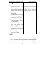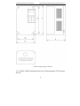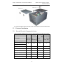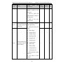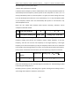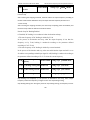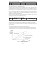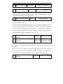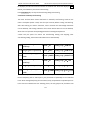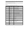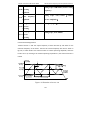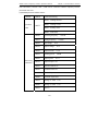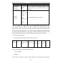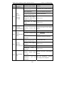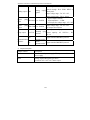
1
VFD-G7 Series High-performance Vector Control General-purpose Frequency Inverter Operation Manual SPECTRA Technology CO., LTD. could supply all-round technology support for clients. The users could contact the nearby agency or customer service center, and also could contact the manufacturer directly. All rights reserved. Any alteration is made without notice. Head office: SPECTRA Technology CO., LTD. Customer hotline: 886-3-7360023 URL: www.spectra-tw.com E-mail: [email protected] Content VFD‐G7 Series Frequency Inverter Operation Manual Content CHAPTER 1 SAFETY AND NOTES ......................................................................................... 1 1.1 SAFETY DEFINITION ............................................................................................................... 1 1.2 SAFETY NOTES ...................................................................................................................... 1 1.3 NOTES ................................................................................................................................ 4 CHAPTER 2 SPECIFICATIONS AND SELECTION ..................................................................... 8 2.1 NAMING RULE ..................................................................................................................... 8 2.2 NAMEPLATE ........................................................................................................................ 8 2.3 MODEL AND TECHNICAL PARAMETERS ...................................................................................... 9 2.4 TECHNICAL SPECIFICATION .................................................................................................... 10 2.5 PRODUCT OUTLINE AND INSTALLATION HOLE SIZES ................................................................... 14 2.5.1 0.4KW~18.5KW Outline and Outer Size of Hang Machine Plastic Casing Frequency Inverter .......................................................................................................... 14 2.5.2 22KW~450KW Outline and Outer Size of Hang Machine Metal Casing Frequency Inverter ............................................................................................................................ 16 2.5.3 0.4KW~450KW Installation Hole Size of Hang Machine G/P Frequency Inverter 17 2.5.4 Outline Size of Keyboard Operation Panel .......................................................... 18 2.6 SELECTION OF BRAKING PACKAGE .......................................................................................... 18 2.7 SELECTION OF DC REACTOR .................................................................................................. 19 2.8 FREQUENCY INVERTER DAILY MAINTENANCE ............................................................................ 20 2.8.1 Daily Maintenance .............................................................................................. 20 2.8.2 Routine Checking ................................................................................................. 21 2.8.3 Replacing of Quick‐wearing Parts ....................................................................... 21 2.8.4 Storage ................................................................................................................ 22 2.8.5 Warranty Instructions .......................................................................................... 22 2.9 SELECTION GUIDE ............................................................................................................... 23 CHAPTER 3 MECHANICAL AND ELECTRICAL INSTALLATION ............................................... 25 3.1 MECHANICAL INSTALLATION.................................................................................................. 25 3.1.1 Installation Environment ..................................................................................... 25 3.1.2 Installation Space ................................................................................................ 25 3.1.3 Cover Removing Way .......................................................................................... 27 3.2 ELECTRICAL INSTALLATION .................................................................................................... 28 3.2.1 External Electrical Component Selection: ............................................................ 28 3.2.2 Instructions For External Electrical Components ................................................. 29 3.2.3 Method Of Connecting Wire ............................................................................... 31 3.2.4 Main Circuit Terminals and Wiring ...................................................................... 32 3.2.5 Control Circuit and Wiring ................................................................................... 35 CHAPTER 4 KEYBOARD OPERATION AND DISPLAY ......................................................... 41 I VFD‐G7 Series Frequency Inverter Operation Manual Content 4.1 INTRODUCTION OF KEYBOARD OPERATION AND DISPLAY INTERFACE ............................................ 41 4.1.1 Descriptions of Key Function ............................................................................... 41 4.1.2 Descriptions of Function Indicators ..................................................................... 42 4.2 POWER ON STATE ............................................................................................................... 44 4.3 DESCRIPTIONS OF FUNCTION CODE CHECK AND MODIFICATION METHOD ...................................... 44 4.4 CHECKING METHOD OF STATE PARAMETER .............................................................................. 45 4.5 PASSWORD SETUP .............................................................................................................. 46 4.6 FAULTS RESET .................................................................................................................... 46 4.7 AUTO‐LEARNING OF MOTOR PARAMETERS .............................................................................. 46 CHAPTER 5 FUNCTION PARAMETER SIMPLE LIST .............................................................. 49 CHAPTER 6 FUNCTIONAL PARAMETER DETAIL .................................................................. 95 6.1 F0 BASIC FUNCTION GROUP ................................................................................................. 95 6.2 F1 START‐STOP CONTROL GROUP ....................................................................................... 107 6.3 F2VF CONTROL PARAMETER GROUP .................................................................................... 112 6.4 F3 GROUP VECTOR AND TORQUE CONTROL PARAMETER .......................................................... 116 6.5 F4 GROUP INPUT SIGNAL GROUP ........................................................................................ 121 6.6 F5 GROUP OUTPUT SIGNAL GROUP ..................................................................................... 127 6.7 F6 GROUP MULTI‐SPEED AND PLC PROGRAM RUN ................................................................ 134 6.8 F7 GROUP PROCESS PID PARAMETER .................................................................................. 138 6.9 F8 GROUP COMMUNICATION PARAMETER ............................................................................ 142 6.10 F9 GROUP HUMAN‐COMPUTER INTERFACE ......................................................................... 144 6.11 FA GROUP ENHANCEMENT FUNCTION GROUP ..................................................................... 146 6.12 FB GROUP PROTECTION FUNCTION GROUP ......................................................................... 150 6.13 FC GROUP APPLICATION PARAMETER GROUP 1 .................................................................... 154 6.14 FD GROUP APPLICATION PARAMETER GROUP 2 .................................................................... 154 6.15 FE GROUP FREQUENCY INVERTER NOUMENON PARAMETER GROUP ........................................ 155 6.16 FF GROUP MONITORING VARIABLE GROUP ......................................................................... 155 CHAPTER 7 COMMUNICATION PROTOCOL .................................................................. 160 7.1 COMMUNICATION ALLOCATION ........................................................................................... 160 7.2 PROTOCOL FORM ............................................................................................................. 160 7.3 PROTOCOL FORM INSTRUCTION ........................................................................................... 160 7.3.1 Data type ........................................................................................................... 160 7.3.2 Salve machine address ...................................................................................... 160 7.3.3 Read function code ............................................................................................ 161 7.3.4 Write operation function code .......................................................................... 165 7.3.5 Abnormal Responding Function Code ............................................................... 168 7.4 CRC PARITY ..................................................................................................................... 170 CHAPTER 8 TROUBLESHOOTING .................................................................................... 172 8.1 FAULTS AND ACTIONS ........................................................................................................ 172 II Content VFD‐G7 Series Frequency Inverter Operation Manual 8.2 COMMON FAULT AND HANDLING METHODS ........................................................................... 176 CHAPTER 9 EMC ......................................................................................................... 178 9.1 DEFINITION ..................................................................................................................... 178 9.2 EMC STANDARD INTRODUCTION ......................................................................................... 178 9.3 EMC DIRECTION .............................................................................................................. 178 9.3.1 Harmonic Influence ........................................................................................... 179 9.3.2 EMI and Installation Notes ................................................................................ 179 9.3.3 Handle interference of the environment to interfere the drive ......................... 179 9.3.4 Handle interference generated by drive to interfere the environment ............. 179 9.3.5 Leakage current and its processing system ....................................................... 180 9.3.6 Note of installing EMC input filter in the power input side ............................... 181 APPENDIX 1 INSTRUCTION OF STANDARD EXPANSION CARD SC‐EXT1‐IO .................... 182 APPENDIX 2 INSTRUCTION OF RELAY‐OUTPUT EXPANSION CARD SC‐EXT2‐R ............... 185 APPENDIX 3 INSTRUCTION OF MULTIFUNCTIONAL INPUT EXPANSION CARD SC‐EXT3‐S ..................................................................................................................... 187 III VFD‐G7 Series Frequency Inverter Operation Manual Content Chapter 1 Safety and Notes 1.1 Safety Definition In this manual, safety precautions divide the following two categories: ! Danger Operations without following instructions can cause personal injury or death. ! Attention Operations without following instructions can cause personal injury or damage to product or other equipment. 1.2 Safety notes ! Danger Before Installations 1. Please don't operate the damaged and incomplete drive. Otherwise there is a danger of human injury 2.Please use the insulation motor which class is above B, otherwise, there is electric shock danger. IV VFD‐G7 Series Frequency Inverter Operation Manual Chapter 1 Safety and Notes ! Danger 2.If more than two drives are parked in the same cabinet, in order to the on cooling effect of Drive, please note fire-retardant material, reserve the that installation position and refer to drive chapter 3 which is mechanical 1. Please install Installing away the from drive combustible and materials, otherwise, it would cause electrical installation. fire alarm! 3. Don't allow Conductors and screws to fall inside the drive, otherwise there is a danger of damage. 1. Only the electrical engineering drive, 5. Don’s connect the input power otherwise, there is electric shock supply to output terminals U, V and danger. W, otherwise, it would cause the 2. Between the drive and power must damage of frequency inverter. have circuit a breaker, otherwise, it 6. Wiring must accord with EMC would cause fire alarm! requirements and the region safety 3. Never wire the drive unless the standards. Please refer to the manual input totally that advised about using wire line disconnected, otherwise, there is diameter. Otherwise accidents may electric shock danger. occur. 4. The drive must be properly earthed 7. Braking resistance cannot be to directly connected into DC between personnel Wiring shall AC reduce wire supply electrical the is accident, otherwise, there is electric shock bus danger. Otherwise there is a danger of fire. 2 (+) and bus (-) terminals. Chapter 1 Safety and Notes VFD‐G7 Series Frequency Inverter Operation Manual ! Danger Before power on 1. Reserve supply voltage and rated 3. The products already have done a voltage of the drive in the same level, penetrative test, if redone, it may make sure the input and output cause accident. wiring correct and check buffer 4. Please refer this manual provided circuit. Otherwise, the drive may be circuit damaged. peripheral 2. Before power on, please make sure electrical accident. to correct accessories, connection to reduce that the cover is installed. Otherwise, can lead to electric shock. 1. After power on, please don’t open 5. When the motor is running, please the cover of the drive, in order to carefully avoid electric shock. Otherwise accidents may occur. 2. Don’t touch the drive and identify parameters. 6. Please don't randomly change the After power on peripheral circuit with wet hands. factory parameters of the drive, 3. Don't touch the drive’s terminals otherwise, will damage the drive. including the control terminals with bare hands. 4. Initial power on, the drive is checking the safety of its external circuit with strong electric, so please don't touch the drive’s terminals U、 V、W and the motor’s terminals. 3 VFD‐G7 Series Frequency Inverter Operation Manual Chapter 1 Safety and Notes ! Danger Operating 1. Please Reserve far away from it, if 4. Don't allow matters to fall inside restart the drive. Otherwise there is the running drive, otherwise it may be human injury. damaged; 2. Don’t touch the cooling fans and 5. Please don’t use contactor to discharge resistance with bare hands control drive start-stop, in order to to test temperature. Otherwise, has reduce the damage. burn dangerous. 3. Amateur technicians do not detect the signal during operating. Or it may cause a personal injury or damaged. Maintaining 1. Please don’t charge for equipment repair and maintenance. Otherwise, have shocking danger; 2. Perform the maintenance and repair job after confirming that the DC Bus voltage is below 36V, in order to avoid electric shock. 3. Unprofessional trained personnel do not charge the repair and maintenance job. Otherwise caused human injury or damaged. 1.3 Notes Insulation checking of motors Before using the drive, the insulation of the motors must be checked, especially, if it is used for the first time, if it has been stored for a long time or regularly check. This is to reduce the risk of the drive from being damaged by the poor insulation of the motor. When checking ,must make sure the motors and the drive is separated, Please use 4 Chapter 1 Safety and Notes VFD‐G7 Series Frequency Inverter Operation Manual 500V insulation tester to measure the insulating resistance. It should not be less than 5MΩ. Motor thermal protection If the ratings of the driven motor are not in compliance with the drive, especially, the drive rated power more than motor rated power, be sure to adjust the protective threshold or to install thermal relay before the motor to ensure the motor is properly protected. Operate above power frequency This drive can provide 0Hz~600Hz output frequency. If the user need to run the motor above rated frequency, please consider the affordability of mechanical devices. The mechanical device resonance The drive system may encounter mechanical resonance with the load when operating within certain band of output frequency. Skip frequencies have been set to avoid it. Motor heat and noise The output voltage is in PWM wave with some harmonics. Therefore, temperature rise, noise and vibration of motor are higher than 50Hz. Varistors or capacitors used to improve the power factor Don't connect any varistor or capacitor to the output terminals of the drive, because the drive's output voltage waveform is PWM, otherwise tripping or damaging of components may occur; in addition, don't install circuit breaker or contactor at the output side of the drive. Circuit breakers connected to the input/output of the drive If contactor is connected between the input power supply and the motor, Please don’t use contactor to control drive start‐stop. If it must be done, interval time should not less than one‐hour. If frequently charging and discharging, the life of the internal capacitance of the drive will be reduced. If circuit breaker or contactor needs to be connected between output side of the drive and the motor, be sure to operate these circuit breakers or contactor when the drive has no output, to avoid damaging of the drive. Using outside the range of rated voltage The drive is unsuitable to be used out of the specified range of operation voltage; 5 VFD‐G7 Series Frequency Inverter Operation Manual Chapter 1 Safety and Notes otherwise, it may be damaged. If need, please use suitable voltage regulation device. Change from 3-phase to 2-phase It is not recommended to change the drive from 3‐phase input to 2‐phase input. Otherwise it will lead to failure or damaged. Protection against lightning strike There are transient surge suppressors inside the Drive which protects it against lighting strike. Department for frequent thunder and lightning, users should install the drive front‐end protection. Derating due to altitude Derating must be considered when the drive is installed at high altitude, greater than 1000m. Because of the thin air, the cooling effect of drive is deteriorated. Please contact our technical advice in this case. Special usage If users need the wiring diagram, such as common DC bus, without in the manual, Please consult our company. Disposing unwanted drive The capacitors may explode when they are burnt. Poisonous gas may be generated when the plastic parts like front covers are burnt. Disposing method: Please dispose the Drive as industrial waste. Adaptive motor 1) If the motor isn’t the four‐pole squirrel‐cage asynchronous induction motor. Please select the drive according to the rated current of the motor. If you choose the permanent magnet synchronous motor, please consult our company. 2) Because the cooling fan of non‐inverter motor is coaxial connection with its rotor shaft connection, if the speed of the motor is reduced, the cooling effect of the fan is deteriorating, if the motor may become overheating in the situation, please change to inverter motor or install another fan. 3) The drive has built‐in adaptive motor standard parameters, According to the actual situation, identify parameters or modify default of the motor to meet the actual value as far as possible; otherwise, it will affect the operating results and the protection of property. 6 Chapter 1 Safety and Notes VFD‐G7 Series Frequency Inverter Operation Manual 4) Because the cable or the inside motor short circuit can cause the drive alarm, and even explosion. Therefore, the initial installing motor and cable must be done insulating short‐circuit test. Note, when doing the test, make sure the drive and the tested part be completely disconnected. 7 VFD‐G7 Series Frequency Inverter Operation Manual Chapter2 Specifications and Selection Chapter 2 Specifications and Selection 2.1 Naming Rule Figure 2-1 Naming rule 2.3 Model and Technical Parameters 8 Chapter2 Specifications and Selection VFD‐G7 Series Frequency Inverter Operation Manual Table2‐1 VFD‐G7 frequency inverter model and technical parameters P Input Output VFD-G7-G0.4S4B capacity(KVA) 1.0 C(A) 2.4 C(A) 1.2 VFD-G7-G0.75S4B 1.5 3.4 2.5 0.75 VFD-G7-G1.5S4B 3.0 5.0 3.7 1.5 VFD-G7-G2.2S4B 4.0 5.8 5.0 2.2 VFD-G7-G3.7/P5.5S4B 5.9 10.5 9/13 3.7/5.5 VFD-G7-G5.5/P7.5S4B 8.9 14.6 13/17 5.5/7.5 VFD-G7-G7.5/P11S4B 11.0 20.5 17/25 7.5/11 VFD-G7-G11/P15S4B 17.0 26.0 25/32 11/15 VFD-G7-G15/P18.5S4 21.0 35.0 32/37 15/18.5 VFD-G7-G18.5/P22S4 24.0 38.5 37/45 18.5/22 VFD-G7-G22/P30S4 30.0 46.5 45/60 22/30 40.0 62.0 60/75 30/37 57.0 76.0 75/90 37/45 69.0 92.0 90/110 45/55 85.0 113.0 110/150 55/75 114.0 157.0 150/176 75/93 134.0 180.0 176/210 93/110 160.0 214.0 210/253 110/132 VFD-G7-G132/P160S4 192.0 256.0 253/300 132/160 VFD-G7-G160/P185S4 231.0 307.0 300/340 160/185 VFD-G7-G185/P200S4 242.0 350.0 340/380 185/200 VFD-G7-G200/P220S4 250.0 385.0 380/420 200/220 VFD-G7-G220/P250S4 280.0 430.0 420/470 220/250 VFD-G7-G250/P280S4 355.0 468.0 470/520 250/280 VFD-G7-G280/P315S4 396.0 525.0 520/600 280/315 VFD-G7-G315/P350S4 445.0 590.0 600/640 315/350 VFD-G7-G350/P400S4 500.0 665.0 640/690 350/400 VFD-G7-G400/P450S4 565.0 785.0 690/800 400/450 VFD Model VFD-G7-G30/P37S4 VFD-G7-G37/P45S4 VFD-G7-G45/P55S4 Input V 3Phase 380V VFD-G7-G55/P75S4 VFD-G7-G75/P93S4 VFD-G7-G93/P110S4 VFD-G7-G110/P132S4 Range: ±15% 9 Motor P(KW) 0.4 VFD‐G7 Series Frequency Inverter Operation Manual Chapter2 Specifications and Selection 2.4 Technical Specification Table2‐2 SVF‐G7 Frequency Inverter Technical Specifications Item Input Output Specification Rated voltage T4 series: Three phase 380v, ±15% Frequency 50/60Hz Voltage Three phase 0-380V Frequency 0-600Hz Overload ability Type G: 150% rated current for 1 minute, ±5% 180% rated current for 2 second; Type P: 120% rated current for 1 minute, 150% rated current for 2 second. Heat Cooling type Forced Cooling Temperature Heatsink temperature >85℃ trip protection protection against overheat Dissipation Heatsink temperature> 50℃, fan forced Fan control operation, frequency inverter continue work Control Performance Open-loop vector control, V/F control, Control mode Torque Control Start torque Open-loop vector control: 0.5Hz 180%; VF control:0.5Hz 150% Speed range Open-loop vector control: 1:200; VF control:1:100 Speed precision control Open-loop vector control: ±0.2%; VF control:±0.5% 10 Chapter2 Specifications and Selection VFD‐G7 Series Frequency Inverter Operation Manual Torque control Open-loop vector control: ±5% precision Torque response Open-loop vector control: <20ms time Function Channel of operation command Keyboard control , terminal control , communication control Start mode Direct start, DC injection braking before start, speed tracking before start DC injection braking Start DC injection braking, stop DC injection braking Dynamic braking Built-in braking unit < = 11kw, get external braking unit>15kw Frequency source choice Keyboard digital frequency setting, analog V1 setting, analog V2 setting, Keyboard potentiometers setting, Multiple speed operation setting, PID control setting, telecommunications setting, PLC program operation setting, HDI High Speed Pulse setting Main and auxiliary Just main frequency setting, just auxiliary frequency frequency setting, QUICK/JOG or terminal combination set switching selection, main frequency + auxiliary frequency, main frequency - auxiliary frequency, maximum, minimum, could realize Frequency overlay and fine adjustment function Frequency resolution Keypad setting:0.01Hz; Analog setting: 0.1% 11 VFD‐G7 Series Frequency Inverter Operation Manual Chapter2 Specifications and Selection Carrier frequency 0.5Khz~15.0Khz, both PWM mode could be chosen Acc/Dec time 0.1~3600.0s Multiple VF curve Linear V/F curve, 2.0 times power drop torque V/F curve, custom V/F percentage (can realize manual energy saving control), multipoint VF curve. Built-in PID Built-in PID controller, apply to process control occasion such as water or gas supply. Meanwhile the sleep wake up function could save energy to the great extent possible. Simple PLC operation 16 segment goal setting, frequency or mode of percentage setting could be chosen, each segment of operation time and direction could be set separately, and realize timing stop function. Common function Speed tracking, Cut-off restart, fault recovery, Automatic torque promotion, the motor’s parameters auto-learning, Pendulum frequency operation, hopping frequency, UP/DOWN control, AVR, Over-voltage stalling protection, rapid current-limiting, Instant power down and drop frequency operation Input Analog input V1:0~10V Output V2:4~20mA or 0~10V, Select through JP2 Signal jumper Keyboard potentiometer input: 0~5V 12 Chapter2 Specifications and Selection VFD‐G7 Series Frequency Inverter Operation Manual Analog output FM1:0~10V or 0~20mA, Select through JP9 jumper FM2:0~10V or 0~20mA, Select through JP10 jumper. Need the support of SC-EXT1-IO expansion cards Digital input Standard configuration S1~S6, can expand S7~S10 through SC-EXT3-S expansion cards. A total of 30 kinds of function could be selected. Digital output Standard configuration 2 channel including SP1, SP2 electrode output; 1 channel relay output T1; Expanding 4 channel relay output T2~T5 through SC-EXT2-R expansion cards. High-speed pulse input HDI: 0~50.0Khz, support by expansion cards SC-EXT1-IO High-speed pulse HDO: 0~50.0Khz, support by expansion output cards SC-EXT1-IO Communicati Communication Based on RS485 hardware, support standard on Port protocol MODBUS protocol, should match expansion cards SC-EXT1-IO Expansion 3 type Cards cards expansion Standard expansion cards SC-EXT1-IO, Relay expansion cards SC-EXT2-R (can realize one Multifunctional drives input 2 function), expansion card SC-EXT3-S, refer to the explanation in Appendix. Display Five digital tube Can monitor the operation state of frequency 13 VFD‐G7 Series Frequency Inverter Operation Manual Chapter2 Specifications and Selection Functions display inverter flexibly and conveniently; can set normal monitoring parameters separately when operation and stop. Protection 25 kinds of Function protection functions Including overheat, over-voltage, overload, over-current, under-voltage, short circuit, ground fault, input and output default phase, protect the frequency inverter running reliably all-round. Installation -10℃~+40℃(ambient temperature is within Environment Ambient Requirement temperature 40℃~50℃, derating use is required), not allow to contact direct sunlight. Humidity Application environment Vibration Elevation Storage temperature Less than 90%RH, without condensation Non-corrosive, flammable, explosive, dust absorbent material, all kinds of lint does not accumulate. Less than0.6G 0~1000m, reduce the rated specification 10% when lift 1000m for each. -20~60℃ 2.5 Product Outline and Installation Hole Size 14 Chapter2 Specifications and Selection VFD‐G7 Series Frequency Inverter Operation Manual Figure 2-4 SVF-G7 Series 22KW~450KW Outline and Outer Size of Hang Machine Metal Casing Frequency Inverter 2.5.3 0.4KW~450KW Installation Hole Size of Hang Machine G/P Frequency Inverter 15 VFD‐G7 Series Frequency Inverter Operation Manual Chapter2 Specifications and Selection Table 2-3 0.4KW~450KW Installation Hole Size of Hang Machine G/P Frequency Inverter (mm) VFD Model W1 H1 W 16 D H Installation Aperture Weight(Kg) Chapter2 Specifications and Selection VFD‐G7 Series Frequency Inverter Operation Manual VFD-G7-G0.4S4B VFD-G7-G0.75S4B VFD-G7-G1.5S4B 96 190 105 154 200 Φ4 2.2 143 233 155 175 245 Φ5 4 196 313 210 189 320 Φ7 7 240 345 255 220 360 Φ6.5 10 160 484 280 262 502 Φ8 17 210 555 346 278 575 Φ8 37 220 619 386 294 643 Φ10 50 260 690 436 313 721 Φ10 61 150+150 750 503 352 785 Φ12 78 220+220 872 688 351 914 Φ12 130 1160 803 397 1206 Φ12 190 1340 820 390 1370 Φ12 250 VFD-G7-G2.2S4B VFD-G7-G3.7/P5.5S4B VFD-G7-G5.5/P7.5S4B VFD-G7-G7.5/P11S4B VFD-G7-G11/P15S4B VFD-G7-G15/P18.5S4 VFD-G7-G18.5/P22S4 VFD-G7-G22/P30S4 VFD-G7-G30/P37S4 VFD-G7-G37/P45S4 VFD-G7-G45/P55S4 VFD-G7-G55/P75S4 VFD-G7-G75/P93S4 VFD-G7-G93/P110S4 VFD-G7-G110/P132S4 VFD-G7-G132/P160S4 VFD-G7-G160/P185S4 VFD-G7-G185/P200S4 VFD-G7-G200/P220S4 VFD-G7-G220/P250S4 150+150 VFD-G7-G250/P280S4 +150 VFD-G7-G280/P315S4 +150 VFD-G7-G315/P350S4 VFD-G7-G350/P400S4 VFD-G7-G400/P450S4 200+200 +200 17 VFD‐G7 Series Frequency Inverter Operation Manual Chapter2 Specifications and Selection 2.5.4 Outline Size of Keyboard Operation Panel 1) Keyboard Outline Dimension (mm) 2) Keyboard Installation Hole Size (mm) Figure 2-5 Keyboard Outline Dimension Figure 2-6 Keyboard Installation Hole 2.6 Selection of Braking Package ☞Note: Table 2‐4 is the guide data, according to the actual situation, the user can choose different resistance and power, (the resistance must not be greater than the recommended value in the table, but the power could.). The motor’s power in the practical application system, determine the braking resistor, which have relationship with system inertia, deceleration time, potential energy of the load, the customer should select according to the actual situation. The greater the system inertia, the shorter the time required deceleration, braking the more frequent, the braking resistor should have the greater power and the smaller resistance. Table 2‐4 Selection ofVFD‐G7 VFD’s Braking Package VFD POWER (KW) Braking Braking Recommended Braking Recommende Braking Resistor Resistor braking resistor Resistor d Braking Unit Power Resistanc TYPE Quantity Unit Quantity (W) e (Ω) 0.4~0.75 SC-BR700-W100 1 100 18 ≥500 Standard Built-in Chapter2 Specifications and Selection VFD‐G7 Series Frequency Inverter Operation Manual 1.5~2.2 SC-BR300-W300 1 300 ≥200 3.7~5.5 SC-BR100-W500 1 500 ≥75 7.5~11 SC-BR70-W1000 1 1000 ≥50 15~18.5 1 2000 ≥40 22~30 2 4000 ≥20 37~55 3 6000 ≥15 5 10000 ≥10 110~132 7 14000 ≥6 160~200 10 20000 ≥4.5 220~250 SC-BR50-W2000 280~315 13 26000 ≥3.5 17 34000 ≥2.5 350~400 20 40000 ≥2 75~93 SC-BR50-W2000 SC-CBU30T 4 SC-CBU55T 4 SC-CBU93T 4 SC-CBU200 T4 SC-CBU200 T4 1 1 1 1 1 2 2.7 Selection of DC Reactor SVF‐G7 Series frequency inverter, G37/P45KW~G400/P450KW all use external DC reactor, (DC reactor usage: power grid harmonic suppression, to improve the input power factor of the inverter.) Users could select the DC reactor based on actual situation. Users need to remove the short circuit copper bars between the main circuit terminals (+) and P when installation, then the DC reactor could be connected between the (+) and P, there is no pole between the reactor terminals and the inverter terminals (+), P. After installing the DC reactor, the short circuit copper bars between (+) and P short circuit is no longer used. Table 2‐5 Selection of VFD‐G7 VFD External DC reactor VFD POWER (KW) Recommended Reactor DC Reactor DC Reactor Rated Notice Configuration TYPE Current(A) 19 VFD‐G7 Series Frequency Inverter Operation Manual Chapter2 Specifications and Selection VFD POWER (KW) Recommended Reactor DC Reactor DC Reactor Rated Notice Configuration TYPE Current(A) Without external reactor terminals 0.4~30 37~55 75~93 110~132 160~200 220~280 315~400 Optional external reactor Standard external reactor DC Without external DC reactor terminals SC-DCL150 150 DC SC-DCL250 250 SC-DCL300 300 SC-DCL400 400 DC SC-DCL600 600 SC-DCL800 800 For the method of external DC reactor, please check the chapter 3 2.8 Frequency Inverter Daily Maintenance 2.8.1 Daily Maintenance Many factors such as ambient temperature, humidity, dust, vibration will casue the internal components aging and give rise to the occurrence of potential faults or lessen the service life of the VFD. Therefore, it is necessary to conduct routine maintenance to the VFD. ! Attention The high voltage still exist in the filter capacitor when the power is off, so maintenance to the VFD couldn’t be performed immediately, it could be performed if the busbar voltage (the voltage between terminals (+) and (-) ) measured by multimeter after 5 minutes is below 36V. Daily inspection items: 1) When running,whether the motor has abnormal sound. 2) When running,whether the motor generates vibration. 3) Whether the installation environment of the VFD changes. 20 Chapter2 Specifications and Selection VFD‐G7 Series Frequency Inverter Operation Manual 4) Whether the cooling fan of the drive is working properly. 5) Whether the VFD is overheating Daily cleaning: 1)Reserve the drive in a clean state. 2)Effectively remove the dust on the surface of the inverter to prevent dust entering the inside of the inverter, especially the metal dust. 3) Effectively clear the oil from the cooling fan. 2.8.2 Routine Checking Check regularly the place which is difficult to check when the drive is running, routine checking items: 1) Check the air duct, and regularly clean. 2) Check whether the screws are loose. 3) Check whether the drive is corroded. 4) Check whether the terminals have arc traces. 5) Check whether the main circuit is insulation. ☞Notes: When using a DC 500V Mega‐Ohm‐Meter to test insulating resistance, please make sure the mian circuit and the frequency inverter is disconnected. please don't use the insulation resistance meter to test the insulation of the control circuit. High voltage test is unnecessary(it has already been conducted before delivery). 2.8.3 Replacing of Quick-wearing Parts The quick‐wearing parts of the frequency inverter mainly includes cooling fan and electrolytic capacitors for filters. Their lifetime depends largely on their application environment and maintenance condition. Normally, lifetime is: Components Life Fan 2~3 years Electrolyte capacitor 4~5 years The user can decide the replace age limit according to the running time. 1.Cooling fan Possible cause of damages: wear of the bearing, aging of the fan vanes. 21 VFD‐G7 Series Frequency Inverter Operation Manual Chapter2 Specifications and Selection Criteria: Check if there is crack on fan vanes and other parts. When the inverter is switched on, check if there is any abnormal vibration. 2. Filtering Electrolytic capacitors Possible cause of damages: the quality of input power is bad, the ambient temperature is high, frequent loading jump and aging of electrolyte. Criteria: Check if there is any leakage of liquids. Check if the safety valve protrudes. Measurement of static capacitance and insulation resistance. 2.8.4 Storage After buying the inverter, when store for temporarily and long‐term, the following notes is important: 1) As far as possible store into the original packaging. 2) Long‐term storage will cause the deterioration of electrolytic capacitors. Therefore, the inverter must be powered within 2 years, and the conduction time is at least for 5 hours. The input voltage must be boosted gradually to the rated value by the voltage regulator. 2.8.5 Warranty Instructions Our company would offer the after sales if the following conditions occur to the frequency inverter: 1) Free warranty is only confined to the frequency inverter itself; 2) Under normal use condition, if there is any faults or damages, our company will take the responsibility of 12 months defects liability period for under the normal operation conditions(from the manufacturing delivery day on, and subject to the machine bar code). After 12 months, reasonable maintenance will be charged; 3). Even within 12 months, maintenance fee would be charged under the following conditions: ① Damages incurred to the inverter due to incorrect operation, which are not in compliance with “User Manual”; ② Damages incurred to the inverter due to fire, flood, abnormal voltage and so on; 22 Chapter2 Specifications and Selection VFD‐G7 Series Frequency Inverter Operation Manual ③ Damages incurred to the inverter due to the improper use of inverter functions; 4. Related service fee will be calculated according to the unified standards of the manufacturer. If there are any maintenance contracts, the contract prevail. 2.9 Selection Guide When selecting the frequency inverter, firstly, you must not only be clear on the technical requirements the system to the frequency inverter, the using situations, the specific load characteristics, but also take other factors such as adapter motor, output voltage and rated output current into consideration, then you can select the models which meet your requirements and make sure the mode of operation. Basic principles: the motor rated load current must not exceed the rated current of the frequency inverter. Generally, choose according to the matched motor capacity stipulated by the instructions, please pay attention to compare the rated current of the motor and the frequency inverter. The overload capacity of the inverter is designed aimed at the short time overload in the process of starting and braking process. For constant torque load or the applications where the load is a little heavies, if there is overload situation in the process of running, it will exceed the output ability of the frequency inverter, so please consider to amplify a grade. Fan and water pump : Fan and water pump types have lower requirements in the overload ability. The load torque is proportional to the square of the speed, so the inverter which running at the low speed has a light load (except for the Roots blower), and because this kind of load has no special requirements on the rotate speed accuracy, the P‐type can be choosed. 23 VFD‐G7 Series Frequency Inverter Operation Manual Chapter 3 Mechanical and Electrical Installation Chapter 3 Mechanical and Electrical Installation ! Warning In order to ensure the safe and reliable running and operation of the products, the frequency inverter must be properly installed and operated under the guidance of qualified personnel .And pay special attention to the work codes and specifications of the high‐voltage. 3.1 Mechanical Installation 3.1.1 Installation Environment 1) Ambient temperature: The surrounding environment and temperature has great influence on the life of the frequency inverter, the running ambient temperature of the frequency inverter should be within the temperature range of ‐10℃~50℃. 2) The frequency inverter should be installed on the surface of the antiflamming goods, there must be enough space for heat dissipation around, install the inverter vertically on the support with the screw. 3) Install in the location where vibration is less than 0.6G, Pay special attention to be away from the punch press and other equipments. 4) Install in the location free of direct sunlight, wet, drops of water. 5) Install in the location Reserve away from corrosive gas ,Flammable gase or explosive gas. 6) Install in the location avoid greasy dirt, dust, metal dust. 3.1.2 Installation Space ≧100mm VFD-G7 A A VFD-G7 24 Chapter 3 Mechanical and Electrical Installation VFD‐G7 Series Frequency Inverter Operation Manual Single Installation Upper and lower Installation ☞Note: When the frequency inverter ☞Note: When two frequenccy inverters power is less than 22KW, size “A” could are mounted one on top the other, an not be considered to install, on the heat insulation guide plate should be contrary, size “A” should be longer than fixedin between as shown in above Fig 50mm. Fig.3‐1 VFD‐G7 Frequency Inverter Installation When installing, the thermal dissipation should be paid attention to. so please note the following: 1) In order to easy to dissipate the thermal, please install the inverter vertically. But can not be inverted. If there are several inverters in the cabinet, the best method is to instal side by side .When two Variable Speed Drives are installed one on top the other, the heat insulation guide plate should be installed between as shown in Fig. 3‐1. 2) The requirements on installation space are shown in Fig. 3‐1 which should ensure the heat dissipation space of the frequency inverter. Layout should ensure the heat dissipation condition of other components in the cabinet. 3) Mounting bracket must be flame‐retardant material. 4) For the location where there is metal powder, the inverter should be mounted outside of the cabinet. If the space is sealed, should make the cabinet having space as large as possible. 3.1.3 Cover Removing Way 25 VFD‐G7 Series Frequency Inverter Operation Manual Chapter 3 Mechanical and Electrical Installation ! Danger When removing the cover, Please avoid it falling down to damage the device and cause personal injury ! 1) Cover Removing of Plastic Casing Frequency Inverter As shown in Figure 3‐2, operate according to serial number, notice that please extract the keyboard first, otherwise, if removing the cover forcibly, it will cause the keyboard and the control board broken. Fig. 3‐2 Removing the above and under cover of the frequency inverters below 22kw 2) Cover Removing of Metal Casing Frequency Inverter As shown in Figure 3-3, operate according to serial number, the control terminals of 75~400KW models need to remove the above cover to wiring, for other models, it only need to remove the below cover to connect the control line. When remove the above cover, please note the connecting line of the keyboard operation panel, and when removing the above cover, please pull the keyboard connecting line from the "J6", when 26 Chapter 3 Mechanical and Electrical Installation VFD‐G7 Series Frequency Inverter Operation Manual recover it, please remember to re-inserted. Fig. 3‐3 Removing the above and under cover of the frequency inverters above 22kw 3.2 Electrical Installation 3.2.1 External Electrical Component Selection: Table 3‐1 0.4KW~400KW frequency inverter external electrical component selection Air VFD Model Recommend Switch(A) ation (MCCB) VFD-G7-G0.4S4B Contactor(A) Recommendat ion Main Circuit Wire(mm²) Recommenda tion Control Circuit Wire 10 10 2.5 1 VFD-G7-G1.5S4B 16 10 2.5 1 VFD-G7-G2.2S4B 16 10 2.5 1 VFD-G7-G3.7/P5.5S4B 25 16 4 1 VFD-G7-G5.5/P7.5S4B 32 25 4 1 VFD-G7-G7.5/P11S4B 40 32 4 1 VFD-G7-G11/P15S4B 63 40 4 1 VFD-G7-G0.75S4B 27 VFD‐G7 Series Frequency Inverter Operation Manual Chapter 3 Mechanical and Electrical Installation VFD-G7-G15/P18.5S4 63 40 6 1 VFD-G7-G18.5/P22S4 100 63 6 1 VFD-G7-G22/P30S4 100 63 10 1 VFD-G7-G30/P37S4 125 100 16 1 VFD-G7-G37/P45S4 160 100 16 1 VFD-G7-G45/P55S4 200 125 25 1 VFD-G7-G55/P75S4 200 125 35 1 VFD-G7-G75/P93S4 250 160 50 1 VFD-G7-G93/P110S4 250 160 70 1 VFD-G7-G110/P132S4 350 350 120 1 VFD-G7-G132/P160S4 400 400 150 1 VFD-G7-G160/P185S4 500 400 185 1 VFD-G7-G185/P200S4 600 600 150*2 1 VFD-G7-G200/P220S4 600 600 150*2 1 VFD-G7-G220/P250S4 600 600 150*2 1 VFD-G7-G250/P280S4 800 600 185*2 1 VFD-G7-G280/P315S4 800 800 185*2 1 VFD-G7-G315/P350S4 800 800 150*3 1 VFD-G7-G350/P400S4 800 800 150*4 1 VFD-G7-G400/P450S4 1000 1000 150*4 1 3.2.2 Instructions For External Electrical Components Table 3‐2 Instructions for VFD‐G7 series VFD external electrical components Name Install Air switch Front MCCB Function Location of When downstream devices is over current, input circuits breaking the power. 28 Chapter 3 Mechanical and Electrical Installation VFD‐G7 Series Frequency Inverter Operation Manual Name Install Function Location Between the air Contactor switch The frequency inverter power on and off, should and the input avoid frequently operating by the contactor or of frequency doing direct start-up operation. inverter Input side of 1) Improve the input power factor of the drive AC Reactor the 2) Suppress the high-order harmonics of the input frequency side; prevent the other equipment damage for the inverter voltage waveform distortion. Input side of Input EMC the Filter frequency inverter 1) Reduce the frequency inverter external conduction and radiation disturbance. 2) Reduce interference of conduction flowing from the power to the drive, and improve the anti-interference ability of the drive. 1)improve the input power factor of the drive Between(+) DC Reactor 2) Improve efficiency and thermal stability of the and P of the whole frequency inverter. main circuit 3) Suppress the high-order harmonics of the input terminals side; reduce external conduction and radiation disturbance. 29 VFD‐G7 Series Frequency Inverter Operation Manual Chapter 3 Mechanical and Electrical Installation Name Install Function Location The output side of the frequency inverter generally contains more the high-order harmonics. When the distance between the frequency inverter Between the output AC Output Reactor side of the frequency inverter and motor. Near the drive and the motor is fart, there is large distributed capacitance in the line, the high-order harmonics may produce resonance in loop, bring two influences: 1) Destroy motor insulation performance, might damage the motor for a long time. 2) Have caused a greater leakage current and the frequency inverter will trip frequently. Generally, when the cables from the frequency inverter to motor are longer than 100m, an output AC line reactor should be used. 3.2.3 Method Of Connecting Wire 30 Chapter 3 Mechanical and Electrical Installation VFD‐G7 Series Frequency Inverter Operation Manual Notice:This drawing applies to VFD-G7-G0.4S4B~VFD-G7-G400/P450S4 Figure3‐4 VFD‐G7 Drawing of Frequency inverter wire connection 31 VFD‐G7 Series Frequency Inverter Operation Manual Chapter 3 Mechanical and Electrical Installation 3.2.4 Main Circuit Terminals and Wiring ! Danger 1.Before wiring, make sure the power switch is OFF,otherwise,can lead to electric shock. 2. Only trained professionals can do wiring, so as to avoid the risk of the drive damage and the personal Injury. 3.The drive must be properly earthed to reduce electrical accident and fire. ! Attention 1. Ensure that the drive’s rated input voltage is identical with the AC supply voltage before using it. 2.Confirm the motor and the drive adaptation, otherwise, make damage the drive or cause the motor triping. 3. It is prohibited to connect the AC supply cables to the drive’s terminals U, V and W. 4. Braking resistor can not be directly connected to the DC bus (+),(-). 1) Introduction of main circuit terminals of the 3‐phase frequency inverter Sign R、S、T (+)、(-) (+)、PB Name Description 3-phase power supply 3-phase 380V AC supply connections input terminals DC bus DC wire(+,-) resistor input common point, Reserved terminals for above 15kw terminals Brake bus external brake kits wiring 11KW and below, the brake resistor terminals connected points 32 Chapter 3 Mechanical and Electrical Installation VFD‐G7 Series Frequency Inverter Operation Manual P、(+) U、V、W Add reactor wiring Add reactor connect point outside terminals outside The frequency inverter Connect 3-phase motor output terminals Earth terminal Earth terminal 2) Wiring Notes: A. Input Power R、S、T: The frequency inverter's input side wiring is not requirements in phase order. B. DC bus terminals (+), (‐) ☞Notice:Wiring can only be done after the drive’s AC power is cut off, then waiting for at least 5mins and confirming the voltage between DC bus terminals plus and minus is below DC 36V. When choosing external braking kits more than 15KW for frequency inverter, do not mistake the terminals (+),(‐), otherwise, can lead to the drive damage and fire. When the cables from the frequency inverter to motor are longer than 10m, multi‐stranded cables or close two‐lane parallel wiring should be used. Braking resistor can not be directly connected to the DC bus, otherwise, cause the risk of the drive damage and fire. C. Brake resistor terminals (+), PB: Less than 11KW, after confirming the drives have built‐in brake kits, the braking resistor terminals are effective. Selection of braking resistor should refer to the recommended value, and wiring distance should be less than 5m. so as to reduce the risk of the drive damage. D. Add reactor connect terminal outside P, (+): G37/P45kW~G400/P450kW frequency inverter, adding reactor outside,remove the 33 VFD‐G7 Series Frequency Inverter Operation Manual Chapter 3 Mechanical and Electrical Installation connected piece between P and (+), then connect the reactor to the two terminals. Frequency Inverter Output Side U. V. W : E. The capacitors or surge absorbers can not be connected to the output side of the drive. Otherwise cause the frequency inverter to trip frequently or even be damaged. Because motor cable is too long, the impact of distributed capacitance produces electrical resonance, which led to the damage of the motor insulation, the drive triping for a greater leakage current. When the cables from the drive to motor are longer than 100m, a AC input reactor should be used. Earth Terminal F. The terminal must be properly earthed, ground resistance must be less than 0.1Ω. Otherwise, lead to equipment abnormal operation or damaged. ☞Notice:It is prohibited to share the earth terminal E and the power zero line terminal N. 3.2.5 Control Circuit and Wiring 1) V1 VFD‐G7main control circuit terminals drawing S1 V2 2) S2 S3 10V GND S4 S5 FM1 SP1 S6 COM TA1 PW 24V SP2 Function of the control terminals Table 3‐3 VFD‐G7 Frequency inverter control terminal introduction The main control circuit terminals Type Terminal Symbol Terminal Name Function 34 TB1 TC1 Chapter 3 Mechanical and Electrical Installation VFD‐G7 Series Frequency Inverter Operation Manual The main control circuit terminals Type Terminal Symbol Terminal Name Function Provide +10V power for outside, Normally External used as working power of the external 10V-GND connection+10v potentiometer, potentiometer resistance range: 1KΩ ~ 5KΩ power Max output current: 10mA Power Provide +24 V power for outside, generally External 24V-COM connection+24v power used as the power of digital input and output terminals and external transducers. Max output current: 200mA The user could directly connect the power to the external power (with COM), it could PW External input power also be connected to the +24V power provide by native machine, PW and +24V are regarded as short circuit when delivery. The short circuit plate should be removed if the external power is used. V1-GND Analog input 1.Input voltage range: DC 0V~10V terminal 1 2. Input resistance: 20KΩ 1. Analog input V2-GND Analog terminal 2 input Input range: DC 0V~10V or 4mA~20mA, Selected by jumper "JP2" on the control board. 2. Input resistance: input voltage 20KΩ, input current 500Ω. 35 VFD‐G7 Series Frequency Inverter Operation Manual Chapter 3 Mechanical and Electrical Installation The main control circuit terminals Type Terminal Symbol Terminal Name Function Multi-function S1-COM digital input terminal 1 Multi-function S2-COM digital input terminal 2 Multi-function S3-COM digital input 1. Opto-coupler isolation Digital terminal 3 2. Input resistance: 3.3 KΩ input Multi-function 3. Input voltage range: 9V~30V S4-COM digital input 4. Programmable multi-function input terminal 4 Multi-function S5-COM digital input terminal 5 Multi-function S6-COM digital input terminal 6 Output voltage or current could be selected Analog output FM1-GND Analog output 1 by the JP9 jumper of the control board. Output voltage range: DC 0V~10V Output current range: DC 0~20mA Digital output SP1-24V Digital output 1 SP2-24V Digital output 2 Open collector output Output voltage range: DC 0V~24V Max output current is 50mA. 36 Chapter 3 Mechanical and Electrical Installation VFD‐G7 Series Frequency Inverter Operation Manual The main control circuit terminals Type Terminal Symbol Terminal Name Function Relay output. TA1-TB1 normal close, Relay TA1-TB1 Normal close/ open TA1-TC1 normal open output TA1-TC1 terminals Contact capacity: AC 250V/3A, DC 30V/1A 3) Explain of jumper Jumper No. Description JP2 Analog input V2 signals Choose DC 0V~10V or 4~20mA input JP9 Analog input FM1 signals Choose DC 0V~10V or 0~20mA output 4) Control terminals: A. Analog wiring description of intput terminals: A. Analog intput terminals Weak analog voltage signal is particularly vulnerable to external interference, so it is generally necessary to use as short as possible shielded cable, wiring is less than 20m, shown in Fig.3‐5. When analog signal is seriously interfered in some occasion, a filter capacitors or a ferrite cores should be used in the analog signal source side, shown in Fig.3‐6. 37 VFD‐G7 Series Frequency Inverter Operation Manual Chapter 3 Mechanical and Electrical Installation Figure 3‐5 Analog input terminal wiring diagram Figure 3‐6 Analog input terminal treatment wiring diagram B. Digital input terminals It is generally necessary to use as short as possible shielded cable, less than 20m C. Digital output terminals When the digital output terminals need to drive the relay, the absorb diode should be installed on both sides of the relay’s coil. Otherwise to cause damage of the DC 24V power. ☞Note: The polarity of the absorb diode must be installed properly, shown in fig.3-7. Otherwise, when the digital output terminal has output signal, immediately the 24V DC power supply will burn out. 38 Chapter 3 Mechanical and Electrical Installation VFD‐G7 Series Frequency Inverter Operation Manual Figure 3‐7 Digital output terminal treatment wiring diagram D. Output terminals of the relay: When the relay output terminals need to control AC contactors and other inductive load. RC snub device such as over-voltage suppressors, which can be bought from the AC contactor manufacturers or the company should be used on both sides of the contactor's coils. Otherwise the drive is easily disturbed and tripping. Shown in fig.3-8. Figure 3‐8 Relay output terminal treatment wiring diagram 39 VFD‐G7 Series Frequency Inverter Operation Manual Chapter 4 Keyboard Operation and Display Chapter 4 Keyboard Operation and Display 4.1 Introduction Of Keyboard Operation And Display Interface Through the keyboard operation panel, we could modify the functional parameter to the frequency inverter, monitor the working condition of the frequency inverter and perform the operational control (start, stop) of frequency inverter, its outline and functional zone are as follows. Fig.4‐1 Illustration of operation panel 4.1.1 Descriptions of Key Function There are 8 keys on the operation panel of the inverter and the function of each key is shown in Figure 4-1. Figure 4‐1 VFD‐G7 Frequency Inverter Keyboard Operation Illustration 40 Chapter 4 Keyboard Operation and Display VFD‐G7 Series Frequency Inverter O peration Manual Key Symbol Name MODE Program key ENTER Data input key ▲ Up/ Increase key ▼ Down/Decrease key Function Enter/exit the first level menu Enter lower level menu or confirm data Increase data or function code Decrease data or function code When modifying the parameter, the modified >> SHIFT bit of the parameter could be selected, in the Right shift key stop display interface and the running display interface, the display parameters could be selected in cycle. In keyboard operation mode, it is used to RUN Run key perform operation, press this key and STOP/RESET in the same time, the frequency inverter will Coast-to-stop. In running status, pressing this key to stop, The STOP Stop/Reset key RESET function is constrained by the function code F9.00 decade; In fault alarm status, all control mode could be false reseted by this key. The function is determined by the unit of the function code F9.00. Multi-function QUICK JOG shortcut key 0: Inching operation; 1: Switch between forward and reverse; 2: Clear the UP/DOWN Setting 3: Main and Auxiliary frequency source switch 4: Torque control stop/effective switch 4.1.2 Descriptions of Function Indicators 41 VFD‐G7 Series Frequency Inverter Operation Manual Chapter 4 Keyboard Operation and Display The operation panel consists of 4 function indicators and 5 unit indicators, the indicative meaning of each indicator is as shown in the following table. 1. Descriptions of Function Indicators Indicator Descriptions of Indicator Name Running Status Indicator OFF: The inverter is in halt mode RUN FLASH: The inverter is in parameters self-learning mode or sleep standby mode. ON: The drive is in running mode Forward/Reverse Indicator REV OFF: Forward ON: Reverse Running Channel Indicator REMOT OFF: Keyboard control mode FLASH: The terminals control mode ON: Remote communication control mode Fault Warning Indicator FAULT OFF: Normal FLASH: Warning mode ON: Fault status 2. Descriptions of unit indicators: Sign Descriptions Hz Frequency unit, Flash: running frequency A Current unit V Voltage unit RPM Rotating speed unit 42 Chapter 4 Keyboard Operation and Display VFD‐G7 Series Frequency Inverter O peration Manual % Percentage 3. Digital Display Area Five LED display could display the setting frequency, output frequency, all kinds of monitoring data and alarm code. 4.2 Power On State After start-up, first, the system of the inverter begins to initialize, the LED will display 8.8.8.8.8, and the 7 indicators all is ON. When finishes the initialization, the drive enter the Standby status. 4.3 Descriptions of Function Code Check and Modification Method The operation panel of VFD‐G7 frequency inverter adopts three‐level menu structure to set the parameter. Three‐level menu consists of functional parameter group (first level menu) →Function code (second level menu) →Function code set value(third level menu). The operation procedure is as the follow figure: Par amet er Al t er i ng Gr oup ENTER MODE 50. 00 F0. 06 MODE f i r st l evel menu Al t er Par amet er Set Val ue ENTER F0 MODE Nor mal Moni t or i ng I nt er f ace Al t er t he Funct i on Code 45. 00 ENTER Conf i r mat i on Set t i ng MODE Exi t Set t i ng second l evel menu t hi r d l evel menu Notes: In the operation of third level menu, both MODE and ENTER could be back to second level menu, the difference is that the ENTER key could be back to the second level menu after saving the setting parameter and then transfer to the next function code automatically, but for the MODE key, it would be back to the second level menu directly without saving the parameter and be back to the current function code. For example: altering the function code F3.14 from 10.00Hz to 12.00Hz. 43 VFD‐G7 Series Frequency Inverter Operation Manual Chapter 4 Keyboard Operation and Display 50. 00 ENTER MODE F0 F3 F3. 00 F3. 14 ENTER MODE F3 MODE F3. 15 ENTER >>/ SHI FT 12. 00 10. 00 10. 00 In the Third level menu state, if the parameter is without flash bit, it indicates that the function code couldn’t be modified, it may be caused by the following reasons: 1) The function code is non-modifiable parameter, such as actual monitoring parameter and run recording parameter and so on. 2) The function code is in the process of running, it couldn’t be modified and only could be modified after stop. The operation panel can do a lot of operations, such as: set the parameters, reset the faults, auto-learn the motor’s parameters, set the password, display the running state and so on, we would introduce all kinds of operation method and procedure in the following. 4.4 Checking Method of State Parameter The user could select the stop normal monitoring variable by setting F9.01 and select the running normal monitoring variable by setting F9.02. When the frequency inverter is powered after the power failure, the shown parameter is defaulted as the selected parameter before power failure. In the stop or run state, the following 6 variables could be shown in cycle by the shift key >>/SHIFT : run frequency (Hz light is flash), setting frequency (Hz light is on), busbar voltage, output current, output voltage, running rotate speed. The FF group parameter is the real time monitoring variable group, which is used to display the value of the corresponding variable in real time. If there is no any pressing key within one minute, it would be back to the normal monitoring interface. 4.5 Password Setup The frequency inverter is with the user password protection function, when the F9.03 is not zero, the user password setting is valid, 1 minute after exiting the function code editing state, 44 Chapter 4 Keyboard Operation and Display VFD‐G7 Series Frequency Inverter O peration Manual and if pressing the MODE key to enter function code editing state, the LED will display 0.0.0.0.0. , the operator must input the user password rightly, or the operator couldn’t enter. If the user wants to cancel the password setting, they need to input the right user password and then set F9.03 to 0. Notes: please set the password cautiously and bear the password in mind, the system fault would be caused if improper operation. 4.6 Faults Reset In the fault status, the inverter will display the related fault information. The user could reset the fault through STOP/RESET key in the keyboard or multi-function input terminal, after the frequency inverter is fault reset, it will be in standby state. If the frequency inverter is still in fault state, it indicates that the user need to check the fault of the frequency inverter carefully and it would fault reset after finding the fault reasons and solving the problem. 4.7 Auto-learning of Motor Parameters The V/F control mode (F0.14=1) is advised for the square-torque load (Fans and water pump type), other constant torque load can use the vector control mode (F0.14=0). If the vector control operating mode is selected, the motor’s nameplate parameters must be exactly input, the inverter will match the standard motor parameters according to the nameplate parameters. In order to obtain a good control performance, auto-learning motor’s parameters is advised, the auto-learning steps is shown in the follow: Firstly, select the start and stop signal to panel start and stop (F0.12=0) , then input the follow parameters according to the motor’s nameplate: F0.16: The motor’ rated voltage. F0.17: The motor’s rated frequency; F3.00: The motor’s rated power; F3.01: The motor’s rated current; F3.02: The motor’s rated rotate speed. 45 VFD‐G7 Series Frequency Inverter Operation Manual Chapter 4 Keyboard Operation and Display The motor’s parameters auto-learning have dynamic auto-learning and static auto-learning, the procedure is as follows: 1. Parameter dynamic auto-learning The parameter dynamic auto-learning can be finished during the motor running, the Acc-time(F0.10) and Dec-time (F0.11) must be reasonably set according to the motor’s power, otherwise, if the Acc and Dec time is too short, it would cause over-current in the process of dynamic auto-learning. First, set the F3.08=1, the panel will display –TUN-, then press the RUN key, the inverter begins to parameter dynamic auto-learn. During the process, the panel will display TUN-0, TUN-1 in turn, when the panel displays -END-, the learning process is over and success. If the drive displays the fault code E020 after the auto-learning, it indicates that mistakes occur to the dynamic parameter auto-learning, the learning process is failure, please confirm the input motor parameters and redo the steps. ☞Note: During the parameter dynamic auto-learning process, the motor and the load should completely disconnect and proceed when the motor stops steadily, otherwise, the obtained motor parameters maybe incorrect. The dynamic auto-learning is advised as far as possible. In case that the motor and the load can not be completely disconnected by the limitation of the scene, the static auto-learning can be used. 2. Parameter Static auto-learning The static auto-learning can be done when the motor is still. First, set the F3.08=2, the panel will display –TUN-, then press RUN key, now the drive begins to statically auto-learn. During the process, the panel will display TUN-0, when the panel displays -END-, the learning process is over and success. If the drive displays the fault code E020, it indicates that mistakes occur to the static parameter auto-learning, the learning process is failure, please confirm the motor’s parameters and redo the steps. 46 Chapter 5 Function Parameter Simple List VFD‐G7 Series Frequency Inverter Operation Manual Chapter 5 Function Parameter Simple List The function parameters of VFD‐G7 series frequency inverter are organized in groups. And there are 16 groups from F0‐FF. Each function group consists of several function codes that are identified by “Function Group No. + Internal Code Number”. For example, “F2.01” indicates group 2 and its function code is 1. ☞Notice 1: It could be used to any load and you should setup F0.16、F0.17 according to the motor’s nameplate. ☞Notice 2:VFD‐G7 series frequency inverters before factory is type G (apply to general used load). If the frequency inverter is used as type P with a large gear (used to the fan and water pump load), the function code F0.15 must be set to 1. ☞Notice 3:VFD‐G7 series frequency inverter before factory is V/F control. If the case needs a big torque, F0.14 can be set to 0 (available to <G200/P220KW, for vector control), but F3.00 to F3.02 must be setup according to the motor’s nameplate, then the drive auto‐learns the motor’s parameters ☞Notice 4: “√” Indicates the parameter can be modified, no matter the drive runs or stops; “×” means the parameter can not be modified while the drive is running. “ ” indicates the parameter can only be read. Table1 Function Parameter Simple List Function Code Name Setting Scope Introduction and Factory Defaults Modify Page 3 × 93 0 × 93 Group F0: Basic Running Parameters Group F0.00 Selection of the main frequency source F0.01 Selection of the auxiliary frequency source 0: Keyboard frequency setting digital 1:Analog V1 setting 2:Analog V2 setting 3: Keyboard 47 VFD‐G7 Series Frequency Inverter Operation Manual Chapter 5 Function Parameter Simple List Function Code Setting Scope Introduction Name and Factory Defaults Modify Page 0 √ 94 100.0% √ 94 0 √ 94 potentiometer setting 4 : Multi-segment speed running setting 5:PID control setting 6: Remote communication setting 7:PLC program running setting 8:HDI high-speed pulse setting F0.02 Auxiliary frequency source standard selection when overlay F0.03 Auxiliary Frequency overlay Scope Main and auxiliary frequency combination mode F0.04 0: Relative to maximum frequency 1: Relative to frequency source main 0.0~150.0% 0:Only main frequency setting 1: Only auxiliary frequency setting 2: QUICK/JOG or terminal switching selection 3: Main frequency + auxiliary frequency (the direction is decided by main frequency) 48 Chapter 5 Function Parameter Simple List VFD‐G7 Series Frequency Inverter Operation Manual Function Code Setting Scope Introduction Name and Factory Defaults Modify Page F0.06(minmum5.00Hz) ~ 600.00Hz 50.00 Hz × 95 4: Main frequency auxiliary frequency ( the direction is decided by main frequency) 5:The maximum of both ( the direction is decided by main frequency) 6:The minimum of both (the direction is decided by main frequency) F0.05 Maximum frequency F0.06 Running frequency upper limit F0.07~F0.05 50.00 Hz √ 95 F0.07 Running frequency lower limit 0.00~F0.06 0.00 Hz √ 95 F0.08 Keypad digital frequency setting 0.00~F0.05 50.00 Hz √ 95 0 × 95 F0.09 output Running direction setting 0: Forward running 1: Reverse running 2: Reverse forbidden F0.10 Acceleration time 0 0.1~3600.0s Type confirm √ 96 F0.11 Deceleration time 0 0.1~3600.0s Type confirm √ 96 F0.12 Operation channel 0: 0 × 96 Keyboard 49 start-stop VFD‐G7 Series Frequency Inverter Operation Manual Chapter 5 Function Parameter Simple List Function Code Name Setting Scope Introduction and Factory Defaults Modify Page selection (“REMOT” light is off); 0 × 97 1 × 100 0 × 100 20~2000V 380V × 101 5.00~F0.05 50.00Hz × 101 1: Terminal start-stop (“REMOT” light is flash)); 2: Communication start-stop (“REMOT” light is on,need support of expansion cards SC-EXT-IO) 0:Two wire type control 1 1:Two wire type control 2 F0.13 Terminal Control Running Mode 2:Three wire type control 1 3:Three wire type control 2 4:Three wire type control 3 F0.14 0: No PG speed vector control; Control mode 1:VF control; 2: No PG torque control F0.15 Model selection type F0.16 Motor voltage rated F0.17 Motor frequency rated 0:G Type 1: P Type 50 Chapter 5 Function Parameter Simple List VFD‐G7 Series Frequency Inverter Operation Manual Function Code Setting Scope Introduction Name and Factory Defaults Modify Page 0 × 101 0111H √ 101 0:No expansion cards 1: Standard expansion cards SC-EXT1-IO F0.18 Expansion type cards 2: Relay expansion cards SC-EXT2-R 3: Multifunctional input expansion card SC-EXT3-S Unit Digit: 0:Invalid 1: Only valid for keyboard digital frequency setting Decade: F0.19 UP/DOWN Setting 0: No storage powering down when 1: Storage when powering down: 0 : Zero clearing when stop 1: No zero clearing when stop F0.20 F0.21 UP/DOWN change rate 0.01~100.00Hz/s 1.00Hz/s √ 102 Modulation function selection The single digit : AVR automatic voltage regulation 0:Invalid 0000H √ 102 51 VFD‐G7 Series Frequency Inverter Operation Manual Chapter 5 Function Parameter Simple List Function Code Setting Scope Introduction Name and Factory Defaults Modify Page Type confirm √ 103 √ 104 √ 104 1: Valid for whole course 2: Only invalid deceleration for Decade:Reserve Hundreds: PWM choose 0:PWM mode 1 1:PWM mode 2 Thousand:Auto-saving 0:Invalid 1:Valid F0.22 F0.23 F0.24 Carrier frequency 0.5~15.0 kHz Voltage of energy consumption brake valve 115.0 ~ 140.0%(standard busbar voltage) Given frequency is less than 0: Run in lower limit frequency frequency Limit 1:Run in zero frequency lower 130.0% (380V series) 120.0% (220V series) 2:Standby state 52 0 Chapter 5 Function Parameter Simple List VFD‐G7 Series Frequency Inverter Operation Manual Function Code Name Setting Scope Introduction F0.25 Holding time of zero frequency runtime output voltage 0.0~6553.5s F0.26 Software version and Factory Defaults Modify Page 3600.0s √ 105 ○ 105 0 × 105 0000H × 105 0:No-operation F0.27 Parameter initialization 1: Recover the factory settings 2: Clear the fault record F1 group: Start/stop Control Parameter Group The single digit : start mode selection 0: Direct-on starting 1: DC braking first, then start Decade:Reserve F1.00 Start choice function Hundreds: Terminal control, restart choice when power-off 0: The terminal operation command is invalid when power-on 1: The terminal operation command is valid when power-on Thousands: Restart selection after power cut 53 VFD‐G7 Series Frequency Inverter Operation Manual Chapter 5 Function Parameter Simple List Function Code Setting Scope Introduction Name and Factory Defaults Modify Page 0.00~10.00Hz 0.00Hz √ 107 in keyboard control 0:No restart 1:Allow auto-restart F1.01 Directly frequency start F1.02 Start frequency holding time 0.0~50.0s 0.0s √ 107 F1.03 DC braking current at start 0.0~150.0% 0.0% √ 107 F1.04 DC braking time at start 0.0~50.0s 0.0s √ 107 0010H × 108 0.00Hz √ 108 The single digit:stopping mode choice 0: Dec to stop 1: Coast to stop F1.05 Stopping function selection Tens: stopping braking use enabled DC 0:Disable 1: Enable, DC braking start frequency decided by F1.06 2: Enable, DC braking start frequency decided by external terminal F1.06 Stopping braking start frequency 0.00 Hz~ F0.05 54 Chapter 5 Function Parameter Simple List VFD‐G7 Series Frequency Inverter Operation Manual Function Code Name Setting Scope Introduction F1.07 Stopping braking waiting time F1.08 Factory Defaults Modify Page 0.0~50.0s 0.0s √ 108 Stopping DC braking current 0.0~150.0% 0.0% √ 108 F1.09 Stopping braking time 0.0~50.0s 0.0s √ 108 F1.10 Power cut restart waiting time in keyboard control 0.0~6553.5s 1.0s √ 109 F1.11 The drop point of frequency for trip-free 70.0% ~ 110.0%(standard bus voltage) 80.0% √ 109 F1.12 Frequency decrease rate trip-free 0.00~50.00Hz/s 0.00Hz/s √ 109 0 × 110 0.0% √ 111 20.0% × 111 DC at and F2 Group: VF Control Parameter Group 0:Linear V/F curve F2.00 V/F curve setting 1: 2.0 times power drop torque V/F curve; 2: Custom percentage; V/F 3:Multipoint VF curve F2.01 Torque boost F2.02 Cut-off frequency of torque boost 0.0: Auto-torque boost 0.1:~30.0% 0.0 ~ 50% ( Rated frequency of motor) 55 VFD‐G7 Series Frequency Inverter Operation Manual Chapter 5 Function Parameter Simple List Function Code Name F2.03 VF point frequency F1 F2.04 Factory Defaults Modify Page 0.1~F2.05 20.0% √ 112 VF point 1 voltage V1 0.1~F2.06 20.0% √ 112 F2.05 VF point frequency F2 F2.03~F2.07 50.0% √ 112 F2.06 VF point 2 voltage V2 F2.04~F2.08 50.0% √ 112 F2.07 VF point frequency F3 3 F2.05 ~ 100.0% ( rated frequency of motor) 70.0% √ 112 F2.08 VF point 3 voltage V3 F2.06 ~ 100.0% ( rated voltage of motor) 70.0% √ 112 F2.09 Custom percentage 50.0~100.0% 100.0% √ 113 0.0~200.0% 0.0% √ 113 1 √ 113 F2.10 Setting Scope Introduction 1 2 V/F V/F Slip compensation gain 0: Enabled and F2.11 Suppress oscillation enabled F2.12 Suppress oscillation low-frequency threshold 0~500 5 √ 113 F2.13 Suppress oscillation high-frequency 0~500 100 √ 114 1: Disabled 56 Chapter 5 Function Parameter Simple List VFD‐G7 Series Frequency Inverter Operation Manual Function Code Setting Scope Introduction Name and Factory Defaults Modify Page threshold F2.14 Amplitude limit of suppress oscillation 0~10000 5000 √ 114 F2.15 Boundary frequency between high and low frequency of suppress oscillation 0.00~F0.05 12.50Hz √ 114 0.4~900.0kW Type confirm × 114 F3 Group: Vector And Torque Control Parameter Group F3.00 Rated power motor1) F3.01 Rated current of motor1) 0.4~1000.0A Type confirm × 114 F3.02 Rated rotating speed of motor1) 0~36000RPM Type confirm × 114 0.001~65.535Ω Type confirm √ 115 0.001~65.535Ω Type confirm √ 115 √ 115 √ 115 F3.03 of Resistance of stator 1) F3.04 Resistance rotor1) of F3.05 Leakage inductance of stator and rotor 0.1~6553.5 mH F3.06 Exciting inductance 0.1~6553.5 mH of 57 Type confirm Type confirm VFD‐G7 Series Frequency Inverter Operation Manual Chapter 5 Function Parameter Simple List Function Code Setting Scope Introduction Name and Factory Defaults Modify Page Type confirm √ 115 0 × 115 stator and rotor 1) F3.07 Current load 1) without 0.1~6553.5A 0: F3.08 Parameter auto-learning Disabled 1: Enabled running) (motor 2: Enabled (motor standstill state) is in F3.09 Proportional gain 1 of speed-loop 0.0~100 20 √ 116 F3.10 Integral gain 1 of speed-loop 0.0~10.00s 0.50s √ 116 F3.11 The low frequency point to switch 0.0 ~ F3.14 5.00 Hz √ 116 F3.12 Proportional gain 2 of speed-loop 0.0 ~100 25 √ 117 F3.13 Integral gain 2 of speed-loop 0.0 ~10.00s 1.00s √ 117 F3.14 The high frequency point to switch F3.11 ~ F0.05 10.00Hz √ 117 F3.15 Coefficient of VC Slip compensation 0 ~200% 100% √ 117 F3.16 The upper limit of VC torque ~ 200.0% the rated current of frequency inverter 150.0% √ 117 58 Chapter 5 Function Parameter Simple List VFD‐G7 Series Frequency Inverter Operation Manual Function Code Name Setting Scope Introduction 0: Keypad frequency setting and Factory Defaults Modify Page 0 √ 118 50.0% √ 0 √ 118 1 × 119 2 × 119 digital 1:Analogue V1 setting F3.17 Choice of torque setting mode 2:Analogue V2 setting 3: Keypad potentiometer setting 4: Telecommunication setting -100.0~100.0% F3.18 Keypad digital torque setting ( 100.0% corresponding upper-limit) the torque 0: Keypad upper-limit frequency(F0.06) F3.19 The source of setting upper limit frequency selection 118 sets 1: Analog V1 sets upper-limit frequency 2: Analog V2 sets upper-limit frequency 3: Telecommunication sets upper-limit frequency F4:Input Signal Group F4.00 S1 terminal function selection 00: No function F4.01 S2 terminal function selection 02: Reverse 01: Forward 03: 3-wire 59 operation VFD‐G7 Series Frequency Inverter Operation Manual Chapter 5 Function Parameter Simple List Function Code Name Setting Scope Introduction and F4.02 S3 terminal function selection control S4 terminal function selection 05:Jog reverse F4.03 S5 terminal function selection 07:Fault reset F4.04 F4.05 S6 terminal function choice 09: Increase (UP) F4.06 S7 terminal function selection F4.07 S8 terminal function selection 12:Multi-speed terminal 1 F4.08 S9 terminal function selection 14:Multi-speed terminal 3 04:Jog forward 06:Free parking 08:External fault input Factory Defaults Modify Page 7 × 119 0 × 119 0 × 119 0 × 119 0 × 119 0 × 119 0 × 119 0 × 119 frequency 10: Decrease frequency (DOWN) 11:Clear the 09 and 10 13:Multi-speed terminal 2 15:Multi-speed terminal 4 16:Pause PID control 17:Pause traverse (hold the current frequency) 18:Traverse reset (return the central frequency) F4.09 S10 terminal function selection 19:Acc/Dec Pause 20:Disable torque control ( under torque control, force to switch speed control) 60 Chapter 5 Function Parameter Simple List VFD‐G7 Series Frequency Inverter Operation Manual Function Code Name Setting Scope Introduction and Factory Defaults Modify Page 21: Temporarily clear the frequency UP or DOWN setting 22: Clear the memorized information of PLC operation 23:Acc/Dec time choice 24: Auxiliary frequency source selection 25: Pause Simple PLC program running 26:Reserve 27:Reserve 28: Stopping DC braking trigger 29:Reserve 30:Reserve F4.10 Filter times of the switch 1~10 5 √ 123 F4.11 V1 low-limit 0.00 ~F4.13 0.00V √ 123 F4.12 The reference value corresponding to lower limit of V1 -100.0 ~100.0% 0.0% √ 123 F4.13 V1 Upper limit F4.11 ~10.00V 10.00V √ 123 61 VFD‐G7 Series Frequency Inverter Operation Manual Chapter 5 Function Parameter Simple List Function Code Name Setting Scope Introduction F4.14 The reference value corresponding to upper limit of V1 F4.15 Factory Defaults Modify Page -100.0~100.0% 100.0% √ 123 Filter time of input V1 0.00~10.00s 0.10s √ 123 F4.16 V2 Lower limit 0.00~F4.18 2.00V √ 124 F4.17 The reference value corresponding to lower limit of V2 -100.0~100.0% 0.0% √ 124 F4.18 V2 Upper limit F4.16~10.00V 10.00V √ 124 F4.19 The reference value corresponding to upper limit of V2 -100.0~100.0% 100.0% √ 124 F4.20 Filter time of input V2 0.00~10.00s 0.10s √ 124 F4.21 HDI rapid pulse frequency low-limit 0.00~F4.23 0.00 kHz √ 124 -100.0~ 100.0% 0.0% √ 124 F4.22 HDI low-limit frequency corresponding setting percentage 62 and Chapter 5 Function Parameter Simple List VFD‐G7 Series Frequency Inverter Operation Manual Function Code Name Setting Scope Introduction F4.23 HDI rapid pulse frequency upper-limit F4.21~50.00kHz F4.24 HDI upper-limit frequency corresponding setting percentage -100.0~100.0% and Factory Defaults Modify Page √ 124 100.0% √ 125 1 √ 125 √ 125 3 √ 125 0 √ 125 0 √ 125 50.00 kHz F5:output signal group 00:No output F5.00 SP1 output choice 01: Frequency inverter is running F5.01 SP2 output choice 02:Frequency inverter is ready(Stop trouble-free) 2 F5.02 Relay 1 choice 03: Frequency Fault F5.03 Relay 2 choice output output inverter 04: Frequency detection output FDT 05: Reference frequency arriving (FAR) 06:Zero-speed running F5.04 Relay 3 choice output 07: Frequency high limit arriving 08: Frequency low limit arriving 63 VFD‐G7 Series Frequency Inverter Operation Manual Chapter 5 Function Parameter Simple List Function Code Setting Scope Introduction Name and Factory Defaults Modify Page 0 √ 125 0 √ 125 09:PLC phase complete output F5.05 Relay 4 choice output 10: PLC cycle complete output time 11:DC braking process 12: Torque output FDT detection 13:Reserve 14:Reserve 15:Inverted running 16:Reserve 17: One drives two cycling and 1# pump variable frequency operation F5.06 Relay 5 choice output 18: One drives two cycling and 1# pump power frequency operation 19: One drives two cycling and 2# pump variable frequency operation 20: One drives two cycling and 2# pump power frequency operation 21: The status of input terminal S1 64 Chapter 5 Function Parameter Simple List VFD‐G7 Series Frequency Inverter Operation Manual Function Code Name Setting Scope Introduction and Factory Defaults Modify Page 22: The status of input terminal S2 23: The status of input terminal S3 24: The status of input terminal S4 25: The status of input terminal S5 26: The status of input terminal S6 27: Frequency alarm status inverter 28: frequency sleep status inverter 29: Braking unit action process 30:Reserve F5.07 SP1 closing delay time 0.0~6553.5s 0.0s √ 127 F5.08 SP1 cutting delay time 0.0~6553.5s 0.0s √ 127 F5.09 SP2 closing delay time 0.0~6553.5s 0.0s √ 127 F5.10 SP2 cutting delay time 0.0~6553.5s 0.0s √ 127 F5.11 Relay 1 TABC output closing 0.0~6553.5s 0.0s √ 127 65 VFD‐G7 Series Frequency Inverter Operation Manual Chapter 5 Function Parameter Simple List Function Code Setting Scope Introduction Name and Factory Defaults Modify Page delay time F5.12 Relay 1 TABC output cutting delay time 0.0~6553.5s 0.0s √ 127 F5.13 FAR width 0.0~100.0%(Maximum output frequency) 0.0% √ 127 F5.14 FDT electrical detection value 00.00~F0.05 50.00Hz √ 128 F5.15 FDT lag detection value 000.0 level) 5.0% √ 128 F5.16 FDT torque level value 0.0~250.0% 100.0% √ 129 F5.17 FDT Torque level detection lagged value 0.0~100.0% 5.0% √ 129 F5.18 FM1output choice 00:Operating frequency 0 √ 129 F5.19 FM2 output choice 01:Setting frequency 3 √ 129 1 √ 129 duration ~ 100.0%(FDT 02:Bus voltage 03:Output current 04:Output voltage F5.20 HDO rapid pulse output choice 05:Operating speed 06:Output power 07:Setting torque 08:Output torque 09:PID setting 66 Chapter 5 Function Parameter Simple List VFD‐G7 Series Frequency Inverter Operation Manual Function Code Setting Scope Introduction Name and Factory Defaults Modify Page 0.0~100.0% 0.0% √ 130 10:PID feedback 11:Analog input V1 12: Analog input V2 13: HDI rapid pulse input choice 14: Potentiometer input VR 15:Reserve F5.21 Lower percentage output FM1 limit of F5.22 The output correspondences the FM1 Lower limit 0.00~10.00V 0.00V √ 130 F5.23 Upper percentage output FM1 0.0~100.0% 100.0% √ 131 F5.24 The output correspondences the FM1 upper-limit 0.00~10.00V 10.00V √ 131 F5.25 FM2 output Lower limit percentage 0.0~100.0% 0.0% √ 131 F5.26 The output correspondences the FM2 Lower 0.00~10.00V 0.00V √ 131 limit of 67 VFD‐G7 Series Frequency Inverter Operation Manual Chapter 5 Function Parameter Simple List Function Code Setting Scope Introduction Name and Factory Defaults Modify Page limit F5.27 FM2 output upper limit percentage 0.0~100.0% 100.0% √ 131 F5.28 The output correspondences the FM2 upper limit 0.00~10.00V 10.00V √ 132 F5.29 HDO rapid pulse output low-limit percentage 0.0~100.0% 0.0% √ 132 F5.30 The output correspondences the HDO low-limit 0.00~50.00kHz 0.00 kHz √ 132 F5.31 HDO rapid pulse output upper-limit percentage 0.0~100.0% 100.0% √ 132 F5.32 The output correspondences the HDO upper-limit 0.00~50.00kHz 50.00 kHz √ 132 F6:Multi-speed and PLC Program Operation F6.00 PLC phase Multi-speed target 0/ 0 -100.0~100.0% 0.0% √ 132 F6.01 PLC phase Multi-speed target 1/ 1 -100.0~100.0% 0.0% √ 132 68 Chapter 5 Function Parameter Simple List VFD‐G7 Series Frequency Inverter Operation Manual Function Code Name Setting Scope Introduction F6.02 PLC phase Multi-speed target 2/ 2 F6.03 PLC phase Multi-speed target Factory Defaults Modify Page -100.0~100.0% 0.0% √ 132 3/ 3 -100.0~100.0% 0.0% √ 132 F6.04 PLC phase Multi-speed target 4/ 4 -100.0~100.0% 0.0% √ 133 F6.05 PLC phase Multi-speed target 5/ 5 -100.0~100.0% 0.0% √ 133 F6.06 PLC phase Multi-speed target 6/ 6 -100.0~100.0% 0.0% √ 133 F6.07 PLC phase Multi-speed target 7/ 7 -100.0~100.0% 0.0% √ 133 F6.08 PLC phase Multi-speed target 8/ 8 -100.0~100.0% 0.0% √ 133 F6.09 PLC phase Multi-speed target 9/ 9 -100.0~100.0% 0.0% √ 133 F6.10 PLC phase Multi-speed target 10/ 10 -100.0~100.0% 0.0% √ 133 69 and VFD‐G7 Series Frequency Inverter Operation Manual Chapter 5 Function Parameter Simple List Function Code Name Factory Defaults Modify Page F6.11 PLC phase Multi-speed target 11/ 11 -100.0~100.0% 0.0% √ 133 F6.12 PLC phase Multi-speed target 12/ 12 -100.0~100.0% 0.0% √ 133 F6.13 PLC phase Multi-speed target 13/ 13 -100.0~100.0% 0.0% √ 133 F6.14 PLC phase Multi-speed target 14/ 14 -100.0~100.0% 0.0% √ 133 F6.15 PLC phase Multi-speed target 15/ 15 -100.0~100.0% 0.0% √ 133 F6.16 PLC phase operation time 0 0.0~6500.0s 0.0s √ 133 F6.17 PLC phase operation time 1 0.0~6500.0s 0.0s √ 133 F6.18 PLC phase operation time 2 0.0~6500.0s 0.0s √ 133 F6.19 PLC phase operation time 3 0.0~6500.0s 0.0s √ 134 F6.20 PLC phase operation time 4 0.0~6500.0s 0.0s √ 134 F6.21 PLC 5 0.0~6500.0s 0.0s √ 134 Setting Scope Introduction phase 70 and Chapter 5 Function Parameter Simple List VFD‐G7 Series Frequency Inverter Operation Manual Function Code Setting Scope Introduction Name and Factory Defaults Modify Page 0.0~6500.0s 0.0s √ 134 0.0~6500.0s 0.0s √ 134 0.0~6500.0s 0.0s √ 134 0.0~6500.0s 0.0s √ 134 0.0~6500.0s 0.0s √ 134 0.0~6500.0s 0.0s √ 134 0.0~6500.0s 0.0s √ 134 0.0~6500.0s 0.0s √ 134 0.0~6500.0s 0.0s √ 134 0.0~6500.0s 0.0s √ 134 0000H × 135 operation time F6.22 PLC phase operation time 6 F6.23 PLC phase operation time 7 F6.24 PLC phase operation time 8 F6.25 PLC phase operation time 9 F6.26 PLC phase operation time 10 F6.27 PLC phase operation time 11 F6.28 PLC phase operation time 12 F6.29 PLC phase operation time 13 F6.30 PLC phase operation time 14 F6.31 PLC phase operation time 15 F6.32 PLC choice function The unit: Cycle mode choice 0:Stop after operating for 1 cycle ( Timing shutdown function can be 71 VFD‐G7 Series Frequency Inverter Operation Manual Chapter 5 Function Parameter Simple List Function Code Name Setting Scope Introduction and Factory Defaults Modify Page × 136 realized) 1:Holding at the final value after single cycle of operation 2:Cycle continuously (Effect after stopping) Tens: PLC breakpoint recovery choice) 0: Run phase 1 again from 1:Continue to run from the stopping phase (retiming) 2:Operate at the time and frequency when the drive stops or fault occurs Hundreds: Power-off, PLC situation store 0:No store 1:Store Thousands : phase tome unit 0:S 1: F6.33 PLC target setting unit choice Min 0: Percentage setting ; 1:Frequency setting F7:Process PID Parameter Group 72 Chapter 5 Function Parameter Simple List VFD‐G7 Series Frequency Inverter Operation Manual Function Code Name Setting Scope Introduction and The unit: PID channel selection given 0: Keypad frequency setting digital Factory Defaults Modify Page 0000H √ 137 1:Analog V1 setting 2:Analog V2 setting 3:keypad potentiometer setting 4:Multi-speed operation setting 5: Telecommunication setting 6:HDI rapid pulse setting F7.00 PID control function choice Tens:PID feedback way choice 0: Analog input V1 feedback 1: Analog input V2 feedback 2: Keypad potentiometer setting 3 :Telecommunication setting feedback 4: HDI rapid pulse feedback Hundreds: PID feature choice output 0: PID output positive 73 VFD‐G7 Series Frequency Inverter Operation Manual Chapter 5 Function Parameter Simple List Function Code Setting Scope Introduction Name and Factory Defaults Modify Page 0000H √ 138 characteristic 1: PID input negative characteristic The unit: disconnection selection Feedback detected 0:Disable 1:Alarm and operation in settled frequency F7.01 Feedback signal protect function choice 2:Breakdown(E022) Tens: over-voltage choice Feedback protect 0: Disable 1: Alarm and operation in settled frequency 2: Breakdown(E024) F7.02 Reference PID preset of keypad 0.0~100.0% 0.0% √ 138 F7.03 Proportional gain 0.00~ 50.00 5.00 √ 138 F7.04 Integral time 0.01~ 50.00s 0.40s √ 138 F7.05 The limit of PID control slip 0.0~100.0% 0.0% √ 138 F7.06 The value feedback disconnection 0.0~100.0% 0.0% √ 139 of 74 Chapter 5 Function Parameter Simple List VFD‐G7 Series Frequency Inverter Operation Manual Function Code Name Setting Scope Introduction and Factory Defaults Modify Page detected F7.07 Feedback disconnection detected time 0.0~ 3600.0s 10.0s √ 139 F7.08 Feedback disconnection alarm operation settled frequency setting 0.00~F0.05 25.00Hz √ 139 F7.09 Sleep frequency F0.07~ F0.05 0.00Hz √ 139 F7.10 Sleep delay 0.0~3600.0s 120.0s √ 139 F7.11 Wakeup value 0.0~100.0% 10.0% √ 139 F7.12 Wakeup delay 0.0~3600.0s 30.0s √ 140 F7.13 PID feedback big values 20.0~100.0% 100.0% √ 140 F7.14 PID feedback big value time 0.0~3000.0s 3.0s √ 140 F7.15 PID feedback big 0.00~F0.05 0.00Hz √ 140 1 √ 140 0003H √ 140 F8:Communication Parameter Group F8.00 Local communication address F8.01 Communication allocation 0: Broadcast address 1~247 The unit:communication baud rate selection 0:1200BPS 75 VFD‐G7 Series Frequency Inverter Operation Manual Chapter 5 Function Parameter Simple List Function Code Setting Scope Introduction Name and Factory Defaults Modify Page 5ms √ 141 0.0s √ 141 0001H √ 141 1:2400BPS 2:4800BPS 3:9600BPS 4:19200BPS 5:38400BPS Tens: Data parity setting 0:No parity (N,8,1)for RTU 1:Even parity (E,8,1)for RTU 2:Odd parity (0,8,1)for RTU 3:No parity (N,8,2)for RTU 4:Even parity (E,8,2)for RTU 5:Odd parity (Q,8,2)for RTU F8.02 Delay responding to for 0~200ms control PC F8.03 The fault time of Communication overtime F8.04 Communication response setting 0.0s(Invalid) 0.1~100.0S The unit: The fault of communicating mistake 0:Alarm and coast to stop 76 Chapter 5 Function Parameter Simple List VFD‐G7 Series Frequency Inverter Operation Manual Function Code Setting Scope Introduction Name and Factory Defaults Modify Page 0000H √ 142 1: No alarm and continue running 2: No alarm and stop in stopping mode(only in serial port control mode) 3: No alarm and stop in stopping mode(in all control modes) Tens: The response of communication: 0: Respond for writing 1: No respond for writing F9:Human-computer Interface Parameter Group The unit: Function of QUICK/JOG key 0:Jog operation 1: Switch between forward and reverse F9.00 Key setting function 2: Clear UP/DOWN the set 3: Main or auxiliary frequency source switch 4: Torque control prohibit/valid switch Tens: Function of STOP/RST key in stop state 0: Valid for panel 77 VFD‐G7 Series Frequency Inverter Operation Manual Chapter 5 Function Parameter Simple List Function Code Name Setting Scope Introduction and Factory Defaults Modify Page 1 √ 143 1: Valid for panel and terminal control in the same time 2: Valid for panel and communication control in the same time 3: Valid for all of the control mode F9.01 Normal monitoring parameter selection when stop 00:Operating frequency (Hz light blink) 01:Setting frequency(Hz light) 02:Bus voltage 03:Output current 04:Output voltage 05:Spinning speed 06:Output power F9.02 Normal monitoring parameter selection when running 07:Setting torque 08:Output torque 09:PID setting 10:PID feedback 11:Analog input V1 12:Analog input V2 13: HDI rapid pulse input frequency 14: The status of input terminal 78 0 143 Chapter 5 Function Parameter Simple List VFD‐G7 Series Frequency Inverter Operation Manual Function Code Name Setting Scope Introduction and 15:FM1 output voltage 16:FM2 output voltage 17: HDO rapid output frequency pulse 18: The status of output terminal 19: Main or auxiliary frequency source indication 20:UP/DOWN frequency value 21: The current stage of multi-stage 22: PLC program operation present stage 23: Potentiometer input voltage 24: Input percentage current 25:Module temperature 26:Inverse module 27: Operation accumulation 28: Motor percentage time overload 29: Frequency inverter overload percentage 30:Reserve 79 Factory Defaults Modify Page VFD‐G7 Series Frequency Inverter Operation Manual Chapter 5 Function Parameter Simple List Function Code Name Setting Scope Introduction and Factory Defaults Modify Page F9.03 Password 1) 0~65535 0 √ 143 F9.04 Reserve F9.05 Accumulated the polarization time -hour H ○ 144 F9.06 Accumulated polarization time-minute Min ○ 144 √ 144 √ 144 √ 144 √ 145 √ 145 144 the FA: Enhanced Functional Parameters Group FA.00 Jog operation frequency 0.00~F0.05 FA.01 Acc time of Jog operation 0.1~3600.0s FA.02 Dec time of Jog operation 0.1~3600.0s FA.03 Acc time 1 0.1~3600.0s FA.04 Dec time 1 0.1~3600.0s FA.05 Run reverse/forward dead time 0.0~3600.0s 0.0s √ 145 FA.06 Skip frequency 0.00~F0.05 0.00Hz √ 145 FA.07 Range 0.00~F0.05 0.00Hz √ 145 of skip 80 10.00Hz Type confirm Type confirm Type confirm Type confirm Chapter 5 Function Parameter Simple List VFD‐G7 Series Frequency Inverter Operation Manual Function Code Setting Scope Introduction Factory Defaults Modify Page 0.0 ~ 100.0%(compared the reference value) 0.0% √ 146 FA.09 Jitter frequency amplitude 0.0 ~ 50.0%(compared traverse operating amplitude) 0.0% √ 146 FA.10 Rising time of Traverse operating 0.1~3600.0s 5.0s √ 146 FA.11 Dropping traverse operating 0.1~3600.0s 5.0s √ 146 FA.12 Coefficient of displayed speed 0.0~1000.0% 100.0% √ 147 FA.13 Reserve FA.14 Reserve FA.15 Current percentage of speed tracking excitation 1) 0.0~200.0% 150.0% √ 147 FA.16 Excitation time 10~3000ms 300ms √ 147 FA.17 Speed calculate decision time1) 20~1000ms 200ms √ 148 FA.18 Voltage output soft-start time1) 0~2000ms 250ms √ 148 The unit:Over voltage at stall protect 1101H √ 148 Name and frequency FA.08 Traverse operating amplitude 1) FB: Protection Function Group Fb.00 Protection function choice 1 81 VFD‐G7 Series Frequency Inverter Operation Manual Chapter 5 Function Parameter Simple List Function Code Name Setting Scope Introduction and Factory Defaults Modify Page 0001H √ 149 0: Disabled 1: Enabled Tens: Current action selection limiting 0: Disabled 1: Enabled Hundreds: Input loss-Phase protection 0: Disabled 1: Enabled Thousands: Output loss-Phase protection 0: Disabled 1: Enabled The unit: Overload protection mode selection 0:Unprotected 1:Protection Fb.01 Protection function choice 2 Tens:Limit effective for Fault reset times 0 : No limit for fault reset 1: Three consecutive failure in three minute, and allow reset after 3 three minutes Hundreds: 82 Group Chapter 5 Function Parameter Simple List VFD‐G7 Series Frequency Inverter Operation Manual Function Code Name Setting Scope Introduction and Factory Defaults Modify Page protection 0: Disabled 1: Enabled Fb.02 Motor overload protection point 20.0 ~ 120.0%(motor rated current) 100.0% √ 149 Fb.03 Bus-wire over voltage at stall 110~150% 130% √ 150 Fb.04 Auto current limiting threshold 100~200% 170% √ 150 Fb.05 Frequency decrease rate in current limiting 0.00~50.00Hz/s 0.00 Hz/s √ 150 Fb.06 Auto reset times 0~3 0 √ 151 Fb.07 Fault automatic reset interval time set 0.1~100.0s 1.0s √ 151 Fb.08 Type of third latest fault 0 ○ 151 0 ○ 151 Fb.09 Type of latest fault E000:No fault E001:IGBT protection 83 shorted VFD‐G7 Series Frequency Inverter Operation Manual Chapter 5 Function Parameter Simple List Function Code Name Setting Scope Introduction and E004:Over-current accelerating process in E005:Over-current decelerating process in Factory Defaults Modify Page 0 ○ 151 E006:Over-cuttent in constant-speed running process Fb.10 Current fault type E007:Over-voltage accelerating process in E008:Over-voltage decelerating process in E009:Over-voltage in constant-speed running process E010:DC Bus low-voltage E011:Motor overload E012:Drive overload E013:Input phase failure E014:Output phase failure E015:Rectifier Heatsink over-temperature E016:IGBT Heatsink over-temperature E017:External fault E018:Serial port communication fault E019:current circuit fault 84 detection Chapter 5 Function Parameter Simple List VFD‐G7 Series Frequency Inverter Operation Manual Function Code Setting Scope Introduction Name and Factory Defaults Modify Page 0.00Hz ○ 152 E020: Motor’s parameter auto-learning fault E021:EEPROM w/r error E022:PID feedback disconnected fault E023:Braking bits fault E024:PID feedback voltage oversize fault E025:Reserve Fb.11 Operating frequency current fault Fb.12 Output frequency of current fault 0.0A ○ 152 Fb.13 DC bus voltage of current fault 0.0V ○ 152 Fb.14 Input terminal state of current fault ○ 152 Fb.15 Output terminal state of current fault ○ 152 Fb.16 Reserve of 152 FC: Apply Parameter Group 1 FC.00 Reserve 152 FC.01 Reserve 152 85 VFD‐G7 Series Frequency Inverter Operation Manual Chapter 5 Function Parameter Simple List Function Code Name Setting Scope Introduction and Factory Defaults FC.02 Reserve 152 FC.03 Reserve 152 FC.04 Reserve 152 FC.05 Reserve 152 FC.06 Reserve 152 Modify Page FD:Apply Parameter Group 2 Fd.00 Reserve 152 Fd.01 Reserve 152 Fd.02 Reserve 152 Fd.03 Reserve 152 FE: Frequency Inverter Body parameter Group FF:Monitoring Parameter Group(This parameter can only be read) FF.00 Operation frequency Unit:0.01Hz ○ 152 FF.01 Setting frequency Unit:0.01Hz ○ 152 FF.02 Bus voltage Unit:0.1V ○ 152 FF.03 Output current Unit:0.1A ○ 153 FF.04 Output voltage Unit:1V ○ 153 FF.05 Operation revolving speed Unit:1RPM ○ 153 FF.06 Output power 100.0% corresponding motor rated power ○ 153 86 Chapter 5 Function Parameter Simple List VFD‐G7 Series Frequency Inverter Operation Manual Function Code Name Setting Scope Introduction FF.07 Setting torque FF.08 and Factory Defaults Modify Page 100.0% corresponding motor rated torque ○ 153 Output torque 100.0% corresponding the frequency inverter rated torque ○ 153 FF.09 PID setting 0.0~100.0% ○ 153 FF.10 PID feedback 0.0~100.0% ○ 153 FF.11 Analog V1 input 0.00~10.00V ○ 153 FF.12 Analog V2 input 0.00~10.00V ○ 153 FF.13 HDI rapid pulse input 0.01~50.00kHz ○ 153 FF.14 Input situation ○ 153 FF.15 FM1 voltage output 0.00~10.00V ○ 153 FF.16 FM2 voltage output 0.00~10.00V ○ 153 FF.17 HDO rapid pulse output frequency 0.01~50.00kHz ○ 153 FF.18 Output situation ○ 153 ○ 153 FF.19 terminal terminal Main and auxiliary frequency source 0: Main frequency source sets frequency 1: Auxiliary frequency source sets frequency 87 VFD‐G7 Series Frequency Inverter Operation Manual Chapter 5 Function Parameter Simple List Function Code Setting Scope Introduction Name and Factory Defaults Modify Page 2:Combination frequency set FF.20 UP/DOWN frequency value Unit:0.01Hz ○ 154 FF.21 Multiple speed current segments 0~15 ○ 154 FF.22 PLC program operation current segments 0~15 ○ 154 FF.23 Potentiometer input voltage 0.00~5.00V ○ 154 FF.24 Percentage output current 100.0% corresponding frequency inverter rated current ○ 154 FF.25 IGBT Heatsink temperature Unit:0.1 ○ 154 FF.26 Inverter module temperature Unit:0.1 ○ 154 FF.27 Total time Unit: Hours ○ 154 FF.28 Motor overload percentage When reaching 100.0% report motor overload ○ 154 FF.29 Frequency inverter overload percentage When reaching 100.0% report frequency inverter overload ○ 154 FF.30 Frequency inverter Model confirm ○ 154 of operating 88 Chapter 5 Function Parameter Simple List VFD‐G7 Series Frequency Inverter Operation Manual Function Code Setting Scope Introduction Name and Factory Defaults Modify Page rated power FF.31 Frequency inverter rated voltage Model confirm ○ 154 FF.32 Frequency inverter rated current Model confirm ○ 154 FF.33 Frequency inverter type ○ 155 FF.34 Output upper-limit frequency Unit: 0.01Hz ○ 155 FF.35 VR potentiometer input percentage 0.0~100.0% ○ 155 FF.36 Analog V1 corresponding percentage -100.0~100.0% ○ 155 FF.37 Analog V2 corresponding percentage -100.0~100.0% ○ 155 FF.38 Rapid pulse input corresponding percentage -100.0~100.0% ○ 155 FF.39 Analog output FM1 corresponding percentage 0.0~100.0% ○ 155 FF.40 Analog FM2 0.0~100.0% ○ 155 output 0:G type 1:P type 89 VFD‐G7 Series Frequency Inverter Operation Manual Chapter 5 Function Parameter Simple List Function Code Setting Scope Introduction Name and Factory Defaults Modify Page corresponding percentage FF.41 Rapid pulse output HDO corresponding percentage 0.0~100.0% ○ 155 FF.42 Main setting Unit:0.01Hz ○ 155 FF.43 Auxiliary frequency setting Unit:0.01Hz ○ 155 FF.44 U phase current per-unit value ○ 156 FF.45 V phase current per-unit value ○ 156 FF.46 W phase current per-unit value ○ 156 Notice: frequency 1) Factory default, do not change the parameter value. 90 VFD‐G7 Series Frequency Inverter Operation Manual Chapter 6 Functional Parameter Detail Chapter 6 Functional Parameter Detail 6.1 F0 Basic Function Group F0.00 Selection of the main frequency source F0.01 Selection of the auxiliary frequency source Default:3 Setting scope:0~8 Default:0 Setting scope:0~8 Select the frequency instruction input channel of the frequency inverter 0: Keyboard digital frequency setting It could be set via F0.08 or and keys on the panel. 1: Analog V1 Setting V1 is the 0~10V voltage input, it need to set the parameter F4.11~F4.15. 2: Analog V2 Setting V2 is the 0~10V voltage input or 4~20mA current input, which could be selected through the jumper JP2, it need to set the parameter F4.16~F4.20. Notes: when selecting the 4~20mA input through the jumper JP2, the corresponding voltage of the input current 20mA is 10V. 3: Keyboard Potentiometer Setting 4: Multi-segment speed running setting Selecting the segment speed by the combination of multi‐function input terminal, to ensure the running frequency by the F4 group multi‐function input terminal segment speed selection and the target setting of F6.00~F6.15. 5: PID Control Setting Select the process PID control output as running frequency. It is generally used in the spot industrial art close loop control, such as constant voltage close loop control, constant tension close loop control, it need to set the F7 group parameter. 6: Remote communication setting The frequency instruction is set by the upper computer communication mode, through MODBUS communication protocol, it is supported by the expansion card SC‐EXT1‐IO of our 91 Chapter 6 Functional Parameter Detail VFD‐G7 Series Frequency Inverter Operation Manual company, it need to set the F8 group parameter and refer to the communication protocol explanation of Chapter 7. 7: PLC program running setting The frequency inverter runs by the simple PLC program, it needs to set the F6 group parameter. 8: HDI high-speed pulse setting The frequency is set through the high‐speed pulse input terminal, it is supported by the expansion card SC‐EXT1‐IO OF our company, it needs to set the F4.21~F4.24 parameter. Auxiliary frequency source F0.02 standard selection when Default:0 frequency scope Setting scope:0~1 overlay F0.03 Auxiliary overlay Default:100.0% Setting scope:0.0~150.0% Auxiliary Frequency Source Standard Selection when overlay 0: Relative to maximum frequency 1: Relative to main frequency source F0.04 Main and auxiliary frequency combination mode Default: 0 Setting scope: 0~ 6 Main and Auxiliary Frequency Combination Mode Setting: 0: Only main frequency setting 1: Only auxiliary frequency setting 2: QUICK/JOG or terminal switching selection 3: Main frequency + auxiliary frequency (the direction is decided by the main frequency) 4: Main frequency ‐ auxiliary frequency (the direction is decided by the main frequency) 5: The maximum of both (the direction is decided by the main frequency) 6: The minimum of both (the direction is decided by the main frequency) 92 VFD‐G7 Series Frequency Inverter Operation Manual Chapter 6 Functional Parameter Detail F0.05 Maximum output frequency Default : 50.00Hz Setting scope: F0.06(Min. 5.00Hz)~ 600.00Hz Set the highest output frequency of the frequency inverter. It is the basis of frequency setting and the acceleration and deceleration speed. F0.06 Running frequency upper limit Default: 50.00Hz Setting scope:F0.07~F0.05 Upper limit value of frequency inverter output frequency. This value should be less than or equal to the maximum output frequency. F0.07 Running frequency lower limit Default: 0.00Hz Setting scope:0.00~F0.06 Frequency inverter output frequency lower limiting value. Relation among the three ones: maximum output frequency>=upper limiting frequency>=lower limiting frequency. F0.08 Keyboard digital frequency setting Default: 50.00Hz Setting scope:0.00~F0.06 When the frequency source is 0(keyboard digital setting), the function code value is regarded as the initial value of frequency inverter digital preset frequency. F0.09 Running setting direction Default: 0 Setting scope:0~2 0: Forward running When the frequency inverter is powered, it runs according to the actual direction. 1: Reverse running Changing this function code can change the motor’s rotation without any other parameter changed, the effect is same to modify any two lines of the motor’s lines (U, V, W) to change the motor’s rotation. ☞Note: after parameter initialization, the motor’s rotation will return to the original state. Please caution in case the motor’s rotation is forbidden changing after the system debugging. 93 Chapter 6 Functional Parameter Detail VFD‐G7 Series Frequency Inverter Operation Manual 2: Reverse forbidden The inverter is reverse forbidden; it is suitable for the special reverse forbidden situation. After reverse forbidden, if there is reverse running control signal, the frequency inverter won’t run. F0.10 Acceleration time 0 F0.11 Deceleration time 0 Default: Model determination Default: Model determination Setting scope:0.1~3600.0s Setting scope:0.1~3600.0s Acc time is the time taken for the motor to accelerate from 0Hz to the maximum frequency (F0.05). Dec time is the time taken for the motor to decelerate from maximum frequency (F0.05) to 0Hz. Actual Acc and Dec time=set Acc and Dec time*(set frequency/max frequency) Fig.6-1 Illustration of Acc/Dec time F0.12 Running channel selection Default: 0 Setting scope: 0~2 Selection of the channel of frequency inverter control instruction. The control command of frequency inverter includes: start, stop, forward, reverse, inching, fault reset. 0: Keyboard start-stop (“REMOT” light is off) 94 VFD‐G7 Series Frequency Inverter Operation Manual Chapter 6 Functional Parameter Detail The start is controlled by RUN key, the stop command is controlled by STOP/RESET key, inching and forward and reverse command are selected and controlled by multi‐function QUICK/JOG key. In the running state, if press RUN and STOP/RESET key at the same time, it would cause the frequency inverter to stop freely. 1: Terminal start-stop (“REMOT” light is flash) Perform run command control through multi‐function input terminals forward, reverse, forward inching, reverse inching and so on. 2: Communication start-stop (“REMOT” light is on) The run command is controlled by the communication mode of upper computer, when selecting this item, the extension card SC‐EXT‐IO of our company must be selected. F0.13 Terminal control running mode Setting scope: 0~4 Default: 0 This parameter defines 5 different modes to control the running of frequency inverter through outer terminals. 0: Two‐wire control 1 This mode is the general used two‐wire control. It is used to control the forward and reverse run of the motor through forward function terminal and reverse function terminal. The setting of multi‐function terminal is as follow: Terminal Setting Description Sx 01 Forward running Sy 02 Reverse running The control mode is as the following figure6-2. K1 K2 Running command 0 95 0 Stop Chapter 6 Functional Parameter Detail VFD‐G7 Series Frequency Inverter Operation Manual K1 0 1 Stop 1 0 Forward 1 1 Reverse Sx Forward running K2 Sy Reverse running COM Figure 6-3 Illustration of Two-wire Running Mode 2 Notes: For two‐wire running mode, when forward function terminal/reverse function terminal is valid and the frequency inverter stops due to the stop command caused by other source, even if the control terminal forward function terminal/reverse function terminal still Reserve valid, the frequency inverter won’t run after the disappearance of stop command, if the user want the frequency inverter to run, it need to trigger the forward function terminal/reverse function terminal again. 2: Three-wire control 1 This three‐wire function terminal mode is enabled terminal, the running command is generated by forward function terminal, the direction command is generated by reverse function terminal, the three‐wire function terminal is normal close. Terminal Setting Description Sx 01 Forward running Sy 02 Reverse running Sn 03 Three-wire running control The control mode is as the figure 6-4. K Running direction 96 VFD‐G7 Series Frequency Inverter Operation Manual Chapter 6 Functional Parameter Detail 0 Forward 1 Reverse Figure 6-4 Illustration of Three-wire Running Mode 1 Among: SB1: running button (normal open); SB2: stop button (normal close). K: forward and reverse switch 3: Three-wire control 2 This three‐wire function terminal mode is enabled terminal, the running command is generated by SB1 or SB3 and it control the running direction at the same time. The stop command is generated by the normal input SB2. Terminal Setting Description Sx 01 Forward running Sy 02 Reverse running Sn 03 Three-wire running control The control mode is as the following figure6-5. Figure6-5 Illustration of Three-wire running mode 2 Among: SB1: forward running button; SB2: Stop button; SB3: reverse running button. 4: Three-wire control 3 The same with three-wire control mode 2, the difference is the stop button is normal open 97 Chapter 6 Functional Parameter Detail VFD‐G7 Series Frequency Inverter Operation Manual button. F0.14 Control mode Setting:0~2 Default: 1 Selection of the control mode of frequency inverter 0: No PG Speed vector control No PG vector control mode refers to open‐loop vector control, which is suitable for low frequency torque, the application where the speed control accuracy requirement is higher, one frequency inverter can only drive one motor. Such as machine tools, centrifuges, draw bench, injection molding machines and other loads. 1: V/F control The V/F control is suitable for the applications which accuracy's requirement is not high, such as fan and pump loads. 2: No PG Torque control The mode is applicable to applications which the accuracy's requirement of torque control is high, such as coiling, draw bench and other applications. After the drive's operation to restore the default value, the reference frequency which is set by panel and UP/DOWN function terminals will be auto‐clear. ☞Note: When selecting the mode of vector’s control, the motor’s nameplate parameter must be set rightly and the motor parameter auto‐learning must be finished before running to obtain the accurate motor parameter, Only obtain accurate motor parameter, the high performance of the vector control could be displayed. By adjusting the vector and torque control parameter (F3 Group), the vector control performance can obtain better performance. F0.15 Model type selection Setting:0~1 Default: 0 0: Applicable to constant torque load 1: Applicable to variable torque load (fan and water pump load) F0.16 Motor rated voltage Default: 380V 98 Setting scope:20~2000V VFD‐G7 Series Frequency Inverter Operation Manual Chapter 6 Functional Parameter Detail F0.17 Motor rated frequency Default: 50.00Hz Setting scope:5.00~F0.05 The motor rated voltage is the max output one. It is the corresponding output voltage when the frequency inverter output the basic running frequency. The motor rated frequency is also known as the basic running frequency, it is the corresponding min frequency when the frequency inverter output max voltage. F0.18 Expansion cards type Setting scope:0~3 Default: 0 Setting the current installed expansion card type: 0: Without installing expansion card; 1: Installing the SC-EXT1-I0 model standard expansion card, see the description of Appendix1; 2: Installing the SC-EXT2-R model relay expansion card, see the description of Appendix2; 3: Installing the SC-EXT3-S model multi-function input terminal expansion card, see the description of Appendix3. F0.19 UP/DOWN setting Default: 0111H Setting scope:0000H~0111H Setting the frequency through ▲、▼ keys on the keyboard and UP/DOWN terminal function (frequency setting increase by degrees/frequency setting decrease by degrees), which is used to fine tuning the output frequency of the frequency inverter in the process of control system debugging. Unit Digit: 0: Invalid 1: It is only valid for the keyboard digital frequency setting Decade 0: No storage when powering down The setting frequency won’t be stored when the frequency inverter is powered down. 99 Chapter 6 Functional Parameter Detail VFD‐G7 Series Frequency Inverter Operation Manual 1: Storage when powering down The setting frequency will be stored when the frequency inverter is powered down. When the power is on, it will combine with the current setting frequency automatically. Hundred 0: Zero clearing when stop The 、 keys on the keyboard and UP/DOWN terminal function are valid in the process of running, automatic zero clearing is set when stopping. 1: No zero clearing when stop The 、 keys on the keyboard and UP/DOWN terminal function are valid when running and stopping. Notes: When the user performs recover default value operation to the function parameter of the frequency inverter, the setting of keyboard and UP/DOWN terminal function will be zero clearing automatically. F0.20 UP/DOWN change Default:1.00 rate Setting scope:0.01~100.00Hz/s Hz/s The rate of change when adjusting and setting frequency of the keys ▲、▼ on the keyboard and UP/DOWN terminals. F0.21 Modulation function selection Default: 0000H Setting scope : 0000H ~ 1111H Unit Digit AVR 0: Invalid 1: Valid for whole course 2: Only invalid for deceleration AVR function is output voltage automatic adjustment function. When AVR function is invalid, the output voltage will vary with the input voltage (or DC busbar voltage); when the AVR function is valid, the output voltage will not vary with the input voltage (or DC busbar voltage), the output voltage will Reserve constant within the output ability scope. When the deceleration time is too long to meet the on site requirement, the AVR function could be 100 VFD‐G7 Series Frequency Inverter Operation Manual Chapter 6 Functional Parameter Detail cancelled to shorten the deceleration time. Decade: Reservation Hundreds: PWM Selection 0: PWM Mode 1 This mode is the normal PWM mode, the motor noise is low in low frequency and the motor noise is big in high frequency. 1: PWM mode 2 The noise in this running mode is low, but the wavelength is high, it needs to derate if selecting the frequency inverter of this function. Kbit: automatic energy saving 0: Invalid 1: Valid The automatic energy saving could be obtained by checking the load current and adjusting output voltage appropriately when the motor is in the process of no‐load or light load. This function is especially valid for fan and pump load. F0.22 Setting scope: Carrier Default: frequency Machine Type confirmation 0.5~150.0kHz This function adjusts the carrier frequency of the frequency inverter. By adjusting carrier frequency, the motor noise could be lower, the point of resonance of the mechanical system could be avoided, which could decrease the disturbance of the circuit to the ground leakage current and the disturbance generated by the frequency inverter. When the carrier frequency is lower, the output current ultraharmonics component will increase, so the loss of machine and motor temperature rising. When the carrier frequency is higher, the loss of machine will lower, the motor temperature rising will lower, but the loss of frequency inverter will increase, the temperature rising and disturbance of frequency inverter will increase. The influence of carrier frequency to the equipment and environment is as the following table: Motor noise↓ 101 Chapter 6 Functional Parameter Detail VFD‐G7 Series Frequency Inverter Operation Manual Motor temperature rising↓ Carrier Output current smoothness↑ Frequency↑ Temperature rise of frequency inverter↑ Leakage current↑ External radiated interface↑ The relation between machine type and carrier frequency is as the following table: Carrier Frequency machine type Max Carrier Min Default Frequency Frequency (kHz) (kHz) (kHz) 0.75~11kW 15.0 0.5 4.0 15~55kW 8.0 0.5 3.0 75~400kW 6.0 0.5 2.0 When the output frequency of frequency inverter is 0Hz, and it is in vector control or V/F control and torque lift, there is the voltage output in the frequency inverter, if running in 0Hz in a long term and there is voltage output, the motor heat dissipation is bad, it is easy to cause the motor heating. The user could set a certain output voltage holding time, after exceeding this holding time, the output voltage will turn to 0, which could prevent the motor from overheating. Default : 130.0%( 380V Setting Range:115.0~ series) Voltage of energy F0.23 140.0%(Standard consumption brake value 120.0% ( 220V bus-wire voltage) series) This function code is the start voltage of setting energy consumption braking unit, if we set this value properly, which could brake the overload effectively. F0.24 Given frequency is less than frequency Default:0 lower limit 0:Operating to lower limit frequency 102 Setting Range:0~2 VFD‐G7 Series Frequency Inverter Operation Manual Chapter 6 Functional Parameter Detail When the given frequency is less than the lower limit one that setting through F0.07, the frequency inverter operate to lower limit frequency 1:Operating to zero frequency When the given frequency is less than the lower limit one that setting though F0.07, the frequency inverter operate to zero frequency. But we should keep certain output voltage according to the work condition. 2:Stand by When the given frequency is less than the lower limit one that setting through F0.07, there is no voltage outputting. Holding Time F0.25 Frequency Output Voltage of Zero Default Runtime 3600.0s : Setting Range:0.0~6553.5s When the output frequency of frequency inverter is 0Hz and the vector or VF control has torque boost, the frequency inverter has certain voltage output with long working to zero frequency, if the motor cooling is bad, those will make the motor getting heater. In case the motor is overheated, the user could set a certain holding time of output voltage, if the time is exceeded, the output voltage would change to zero. F0.26 Software Version Default: Setting scope: It is used to show the software version number, this function code could only be checked, and couldn’t be modified. F0.27 Parameter Initialization Default:0 Setting scope:0~2 0: No operation 1: When the parameter recovers default, the frequency inverter would recover all parameter to default. 2: Eliminating recent failure logging. 6.2 F1 Start-Stop Control Group F1.00 Start function selection Default: 0000H Unit digit: start mode selection 103 Setting scope:0000H~1102H Chapter 6 Functional Parameter Detail VFD‐G7 Series Frequency Inverter Operation Manual 0: Direct‐on starting Start from the preset starting frequency (F1.01). 1: DC braking first, then start DC braking first, then start from starting frequency. It is suitable for small inertia load which may reverse at the start. 2: Speed tracking, then start Firstly, the frequency inverter calculates the motor’s running speed and direction, and move to setting frequency from tracking speed to achieve smooth no‐impact start to the rotating motor. The method is applicable the large inertia load to re‐start after the drive stops instantly. Notes: the machine type below 5.5kw is without speed tracking function. Decade: Reserve Hundred: Power on terminal running protection selection When the running instruction channel is terminal control, in the process of power on of the frequency inverter, the system will detect the running terminal’s state automatically, and conduct corresponding control according to the multi‐function input terminal function. 0: terminal running command is invalid when power on Even though the running command terminal is detected valid in the process of power on, the frequency inverter will not run, the system will in the running protection state, until disconnecting the running command terminal, then to close the terminal, the frequency inverter will run. 1: Terminal running command is valid when power on If the running command terminal is detected valid in the process of power on, after the initialization, the system will start the running of frequency inverter automatically. This set could achieve the restart after power cut function under the control of terminal. Notes: this function may cause serious consequence, the user should select cautiously. Kbit: restart after power cut function under the keyboard control 0: Restart banned It indicates that the frequency inverter won’t start automatically when power on once again 104 VFD‐G7 Series Frequency Inverter Operation Manual Chapter 6 Functional Parameter Detail after the frequency inverter power down. 1: Restart after power down is allowed It indicates that the frequency inverter would be back to the running state before power cut automatically when the frequency inverter power on after the power cut. That is, if it is in running state before power cut, after the power is on again, the restart waiting time set by F1.10 will be delayed and it will start to run automatically, if it is in stop state before power cut, the frequency inverter won’t start automatically after power on. This function is only valid to keyboard control. Notes: the user should select allowed restart function cautiously, otherwise, serious consequence would be caused. Defaul:0.00Hz Setting scope:0.00~10.00Hz F1.01 Directly start frequency F1.02 Start frequency holding time Default:0.0s Setting scope:0.0~50.0s Setting the appropriate starting frequency can increase the starting torque. Within start frequency holding time (F1.02), the frequency inverter output frequency is the start frequency, and then run from the start frequency to the target frequency, if the target frequency is less than start frequency (F1.01), the frequency inverter will not run and will be in the standby state. Starting frequency (F1.01) is not restricted by the lower limit frequency. In the process of forward and reverse switch, the start frequency (F1.01) will not function. F1.03 Start current DC braking Default: 0.0% F1.04 Start DC braking time Default: 0.0s Setting scope:0.0~150.0% Setting scope:0.0~50.0s When the drive starts, first to DC braking with the preset start DC braking current, after the preset start DC braking time, the drive will begin to accelerated run. The DC braking is invalid if the setting DC braking time is 0. DC braking current is greater, the braking force is greater. Starting the DC braking current is a percentage value relative to the drive’s rated current. 105 Chapter 6 Functional Parameter Detail VFD‐G7 Series Frequency Inverter Operation Manual F1.05 Stop function selection Default: 0010H Setting scope:0000H~0021H Unit digit: stop mode selection 0: Dec to stop After receiving the stopping command, the drive reduces its output frequency according to the Dec mode and the defined Dec time, and stops when the frequency decreases to 0. 1: Coast to stop After receiving the stopping command, the drive stops outputting power immediately and the motor stops under the effects of mechanical inertia. Decade: Stop DC Braking Enabled 0: Disabled, DC braking is not conducted when deceleration and stop; 1: The start frequency of DC braking is decided by F1.06 In the process of deceleration and stop, when the output frequency is less than the frequency set by F1.06, braking is conducted according to the parameter defined according to F1.07~F1.09. 2: The start frequency of DC braking is decided by external terminal In the process of deceleration and stop, when one multi-function input terminal is set to 28 and the corresponding terminal input signal is valid, braking is conducted according to the parameter defined according to F1.07~F1.09 at the current frequency. F1.06 Stop braking start frequency Default: 0.00Hz Setting scope:0.00Hz~F0.05 F1.07 Stop braking waiting time Default: 0.0s Setting scope:0.0~50.0s F1.08 Stop DC braking current Default: 0.0% Setting scope:0.0~150.0% F1.09 Stop DC braking time Setting scope:0.0~50.0s Default: 0.0s Stop braking start frequency: in the process of deceleration and stop, when output frequency reaches this frequency, it begins to enter into stop braking waiting; Stop braking waiting time: during the period of stop braking waiting, the frequency inverter 106 VFD‐G7 Series Frequency Inverter Operation Manual Chapter 6 Functional Parameter Detail would block the output, DC braking will be conducted after the delay. It is used to prevent the over current fault caused by DC braking when the speed is higher. Stop DC braking current: it refers to the added DC braking value. The bigger the value, the bigger the braking torque. Stop DC braking time: the duration time of DC braking. out put f r equency st op br aki ng st ar t f requency t out put vol t age st op DC br aki ng t i me st op DC braki ng t st op braki ng wai t i ng t i me runni ng command st op command t Figure 6-6 Illustration of stop DC braking F1.10 Power cut restart waiting time Default: 1.0s in keyboard control Setting scope:0.0~ 6553.5s If the frequency inverter is in running state before power cut, and restart after power cut is allowed, after the power is on again, the setting time will be delayed and it will start to run automatically. Setting scope: F1.11 The frequency drop point when trip-free Default:80.0% 70.0%~110.0%standard busbar voltage F1.12 Frequency decrease rate Default:0.00Hz/s Setting 107 voltage : 0.00Hz/s ~ Chapter 6 Functional Parameter Detail VFD‐G7 Series Frequency Inverter Operation Manual when trip-free 50.00Hz/s When the frequency scale of decrease after power cut immediately is set to 0, frequency drop function after power cut immediately is invalid. Frequency point drop after power cut immediately: after the power grid power down, busbar voltage is down to Frequency point drop after power cut immediately, the frequency inverter begin to low the running frequency according to frequency scale of decrease after power cut immediately to Reserve the motor in generating state and to maintain the busbar voltage by the feedback electric energy, which could guarantee the normal running of frequency inverter until the next power on. Adjusting these two parameters properly could avoid the production halt caused by frequency inverter protection during power grid switch. 6.3 F2 VF Control Parameter Group F2.00 V/F curve setting Default: 0 Setting scope:0~3 This group function code is valid to V/F control (F0.14=1), and is invalid to vector control. 0: Linear V/F curve, it is applied to constant torque load, the output voltage is linear with output frequency. 1: 2.0 times power drop torque V/F curve, see the curve in figure 6‐7; 2: Custom V/F percentage, it can realize manual energy saving control by adjusting F2.09; 3: Multipoint VF curve, it can set the needed V/F curve through function code F2.03~F2.08. Figure 6-7 Illustration of V/F curve 108 VFD‐G7 Series Frequency Inverter Operation Manual Chapter 6 Functional Parameter Detail Setting scope:0.0%:automatic torque boost F2.01 Torque boost Default: 0.0% 0.1~30.0% Cut-off F2.02 frequency of Default: 20.0% Setting scope:0.0~50.0%(motor rated frequency) torque Boost Torque boost is mainly used in below the cut‐off frequency (F2.02), after boost, the V/F curve after boost is shown in fig. 6‐8, the torque boost can improve the V/F low frequency’s torque characteristics. Select the value of torque according the size of loads. The big loads can select a bigger boost, but the torque boost can not be set too big. If the torque boost is too large, motor will run with over excitation, the output current will increase, the motor will be easy to overheat, the drive's output current will be big, the efficiency will reduce. When the torque boost is set to 0.0%, the inverter is auto torque boost. Cut‐off point of torque boost: the linear V/F curve is valid, under this frequency point, the torque boost is valid, over the point; the torque boost is invalid. Figure 6-8 Illustration of torque boost F2.03 VF point 1 frequency F1 Default: 20.0% 109 Setting scope:0.1~F2.05 Chapter 6 Functional Parameter Detail VFD‐G7 Series Frequency Inverter Operation Manual F2.04 VF point 1 voltage V1 Default: 20.0% VF point 2 frequency Default: 50.0% Setting scope:F2.03~F2.07 VF Point 2 Voltage V2 Default: 50.0% Setting scope:F2.04~F2.08 F2.05 F2 F2.06 Setting scope:0.1~F2.06 VF point 3 frequency F2.07 F3 Setting scope:F2.05~100.0% Default: 70.0% (motor rated frequency) Setting scope:F2.06~100.0% F2.08 VF point 3 voltage V3 Default: 70.0% (motor rated voltage) The above six parameters F2.03~F2.08 define multipoint V/F curve, as shown in figure 6‐9. The set value of V/F curve is usually set according to motor’s load characteristics. Notes: V1<V2<V3,F1<F2<F3. If the low frequency voltage is set too high, it would cause overheat of the motor and even burned and the frequency inverter maybe be over current and stall or over current protection. Figure 6-9 Illustration of V/F curve setting 110 VFD‐G7 Series Frequency Inverter Operation Manual Chapter 6 Functional Parameter Detail F2.09 Custom V/F percentage Default: 100.0% Setting scope:50.0~100.0% F2.10 V/F slip compensation gain Default: 0.0% Setting scope:0.0~200.0% Setting this parameter could compensate the motor speed change caused by the load in V/F control, which can improve the hardness of motor mechanical characteristics, this value is corresponding to the motor’s rated slip frequency. Setting scope:0~1 F2.11 Suppress oscillation enabled Default: 1 0: Suppress oscillation valid 1: Suppress oscillation invalid The function code of suppression oscillation is for V/F control, the common motor with no‐load or light‐load often has current oscillation to lead the motor’s abnormal operation, the serious can cause drive over current. When the F2.11 is selected to 0, the suppressing oscillation function is enabled, the drive will suppress the motor’s occurring oscillation according to the parameters of functions F2.12~F2.15. F2.12 F2.13 Suppress oscillation low-frequency oscillation low-frequency threshold Suppress threshold Default:5 Setting scope:0~500 Default:100 Setting scope:0~500 When most of motors run in some frequency band, the current oscillation will easily occur, light case is that the motor can not stable operate, the serious situation will lead the drive over‐current. When F2.11 is set to 0, suppress oscillation is valid. When F2.12 and F2.13 have small reference values, the effect of the suppress oscillation is evidence, the addition of the current is evidence; if the settings is large, the effect of suppress oscillation is weak. F2.14 Amplitude limit of suppress oscillation 111 Default: 5000 Setting scope:0~10000 Chapter 6 Functional Parameter Detail VFD‐G7 Series Frequency Inverter Operation Manual When suppress oscillation, the parameter can be used to limit the boost value of big voltage. F2.15 Boundary frequency between high and Default : Setting scope:0.00~ low frequency of suppress oscillation 12.50Hz F0.05 F2.15 is the boundary of the function codes F2.12 and F2.13. 6.4 F3 Group Vector and Torque Control Parameter Motor rated Default: Dependent on drive’s F3.00 power Motor model rated Default: Dependent on drive’s F3.01 current F3.02 Motor rated speed Setting scope:0.4~ 900.0KW Setting scope:0.4~ model 1000.0A Default: Dependent on drive’s Setting scope:0~ model 36000RPM ☞Note: please set with reference to the values on the motor’s nameplate. Excellent control performance of vector control should have accurate motor’s parameters. The drive has auto‐learning function of motor’s parameters. Only correctly setting the parameters of the motor’s nameplate can ensure the accuracy of auto‐learning. In order to ensure the control performance, please configure the motor according to standard adaptive motor of the frequency inverter. If the motor’s power and that of standard adaptive motor have a wide gap, the control performance will significantly decrease. ☞Note: the motor parameter from F3.01 to F3.07 could be initialized by resetting motor rated power F3.00. F3.03 Resistance stator Resistance F3.04 rotor Leakage of Default: Dependent on drive’s model of Default: Dependent on drive’s model Default: Dependent on drive’s 112 Setting scope:0.001~ 65.535Ω Setting scope:0.001~ 65.535Ω Setting scope:0.1~ VFD‐G7 Series Frequency Inverter Operation Manual Chapter 6 Functional Parameter Detail F3.05 inductance of model 6553.5mH stator and rotor Exciting F3.06 inductance of stator and rotor Current Setting scope:0.1~ Default: Dependent on drive’s model 6553.5mH Setting scope: 0.1~ without Default: Dependent on drive’s F3.07 load model 655.3.5A When the auto‐learning of motor’s parameters normally ends, the setting value from F3.03 to F3.07 will automatically update. These parameters are the benchmarks of high‐performance vector control, and directly affect the control performance. ☞Note: Users do not arbitrarily change the group of parameters. F3.08 Parameter auto-learning Default: 0 Setting scope:0~2 0: No operation The auto‐learning is banned. 1: Dynamic auto‐learning Before starting auto‐learning, please ensure the motor and load being disconnected, Reserve the motor no‐load and confirm the motor in the standstill state. Values on the motor’s nameplate (F3.01~F3.02) must be input correctly before starting auto‐learning, otherwise, the auto‐learned parameters are not correct. The size of Acc/Dec time (F0.10~F0.11) should be properly set according the size of the motor’s inertia before starting auto‐learning, otherwise, the over‐current fault may be caused during auto‐learning. F3.08 is set to 1, then press ENTER key, the system begins auto‐learning. Now, the LED flashing displays ‐TUN‐, press RUN key, the LED displays TUN‐0, after the motor running, TUN‐1 is displayed and the light RUN flashes. When the auto‐learning ends, the ‐END‐ will 113 Chapter 6 Functional Parameter Detail VFD‐G7 Series Frequency Inverter Operation Manual be displayed, the LED will return the interface in standstill state. When the displayed ‐TUN‐ flashed, press MODE key can exit the auto‐learning. Press STOP/RESET key can stop the auto‐learning during auto‐learning. 2: Parameter stationary auto‐learning The motor and load don’t need to disconnect in stationary auto‐learning. Values on the motor’s nameplate (F3.00~F3.07) must be input correctly before starting auto‐learning. After auto‐learning, the stator’s resistance, rotor’s resistance and the leakage inductance can be detected, and exciting inductance and current without load can not be detected, which users can input the corresponding parameters according the experience. ☞Note: Only the panel can control the auto‐learning starting and stopping; after auto‐learning ending, the function code will be set to 0 automatically. F3.09 Proportional gain 1 of speed-loop Default:20 F3.10 Integral gain 1 of speed-loop Default:0.50s F3.11 F3.12 The low frequency point to switch Proportional gain 2 of speed-loop The high frequency point to switch Setting scope:0.0~10.00s Default:5.00Hz Setting scope:0.00~F3.14 Default:25 F3.13 Integral gain 2 of speed-loop Default:1.00s F3.14 Setting scope:0.0~100 Setting scope:0.0~100 Setting scope:0.0~10.00s Default:10.00Hz Setting scope:F3.11~F0.05 The above parameter is valid only for vector control, and invalid for V/F control. Under the low frequency point to switch (F3.11), the parameters of speed‐loop PI are F3.09 and F3.10. Above the high frequency point to switch (F3.14), the parameters of speed‐loop PI are F3.12 and F3.13. Between the two switching points, the two groups of PI parameters will 114 VFD‐G7 Series Frequency Inverter Operation Manual Chapter 6 Functional Parameter Detail obtain via linear change By setting the speed regulator proportional coefficient and integral time, can adjust the dynamic response speed of vector control. Increasing the proportional gain and reducing the integration time, can accelerate the dynamic response of speed loop dynamic, but too large proportional gain or too small integration time easily lead to system oscillation, and excessive overshoot too small Proportional gain can easily cause the system to steady state oscillation, and speed static error. PI speed loop parameters and the inertia of the motor system have close relationship. Users need to adjust it based on default PI parameters of different load characteristics to meet the requirements of various occasions. F3.15 Coefficient of VC slip compensation Default: 100% Setting scope:0~200% For no velocity sensor vector control, this parameter is used to adjust motor's speed control precision. Increase the parameter if the motor load speed is low, conversely, it is in converse. F3.16 The upper limit of reference torque Setting scope:0.0~200.0% Default: 150.0% rated current of frequency inverter The reference value 100% corresponds to the rated output current of drive. F3.17 Choice of torque setting mode Default: 0 Setting scope:0~4 Torque instruction input channel of frequency inverter is defined. When torque is set to minus, the motor will reverse. 0: Keypad digital frequency set 1: Analogue V1 setting 2: Analogue V2 setting 3: Analogue input V1+V2 115 Chapter 6 Functional Parameter Detail VFD‐G7 Series Frequency Inverter Operation Manual 4: Telecommunication setting When the torque control is valid, the drive will output torque according to the reference torque, the output frequency is limited by the upper and down limit of frequency. When the reference torque of drive is bigger than load’s torque, the output frequency of drive will rise until the upper frequency. When the reference torque is less than load’s torque, the output frequency of drive will fall until down frequency. When the output frequency of the frequency inverter is limited, the output torque may be similar with the setting torque. Notes 1:When it is set to 1~4,100% is corresponding to 2 times rated current of the frequency inverter. Notes 2:It could be switched between torque control and speed control through multi-function input terminal. Notes 3:When there is stop command on torque control, it will switch to speed control automatically. Setting scope:-100.0~100.0% F3.18 Keyboard torque setting digital Default: 50.0% ( 100.0%corresponding to upper torque) When the torque command is set by keyboard (F3.17=0), the parameter should be set. F3.19 The source of setting upper limit frequency selection Default: 0 Setting scope: 0~3 There are many kinds of source which can be selected by F3.19 to set the upper limit of frequency. Especially, during torque control, the output frequency of drive can be changed by changing the upper limit of frequency. 0: Upper limit of frequency (F0.06) is set by keyboard 1: Upper limit of frequency (F0.06) is set by Analog V1 116 VFD‐G7 Series Frequency Inverter Operation Manual Chapter 6 Functional Parameter Detail 2: Upper limit of frequency (F0.06) is set by Analog V2 3: Upper limit of frequency (F0.06) is set by Remote communication Notes 1:When it is set to 0-3,100% correspond to the max frequency F0.05. 6.5 F4 Group Input Signal Group F4.00 S1 Terminal function selection Default: 1 F4.01 S2 Terminal function selection Default: 2 F4.02 S3 Terminal function selection Default: 7 F4.03 S4 Terminal function selection F4.04 S5 Terminal function selection F4.05 S6 Terminal function selection F4.06 S7 Terminal function selection F4.07 S8 Terminal function selection F4.08 S9 Terminal function selection F4.09 S10 Terminal function selection Setting scope: 0~30 Default: 0 0: No function Even if there are input signals, the drive will not run. The unused terminals can be set no function in order to avoid malfunction. 1: Forward 2: Reverse The external terminals control the drive operating direction. 3: 3‐wire operation control The terminal is used to set the drive’s operating mode of 3‐wire operation control, please refer to the description of 3‐wire operation control function code F0.13. 4: Jog forward 5: Jog reverse 117 Chapter 6 Functional Parameter Detail VFD‐G7 Series Frequency Inverter Operation Manual It is the frequency of Jog operating. The Acc/Dec time of Jog operation can be referred to the description of function codes FA.00~FA.02. 6: Coast to stop (only valid when terminal control F0.01=1) The stop process will not be controlled by drive. It is the common method of great load inertia and no requirement of stop time. 7: Fault reset The function is same as the STOP/RESET key. The function can achieve Remote Fault Reset. 8: External fault input When the drive receives the signal of external fault, the drive will alarm and stop. 9: Frequency setting increase (UP) 10: Frequency setting decrease (DOWN) 11: Frequency increase and decrease (UP/DOWN) setting clearing When the reference frequency is set by external terminals, the function will be used to adjust the frequency increase instruction and decrease instruction. When the source of reference frequency is the digital setting, the function can be used to adjust the reference frequency for up/down, the terminal speed regulation is as shown in fig,6‐10. Figure 6‐10 Illustration of terminal speed regulation The terminals can be used to clear the reference frequency by UP/DOWN, and make the frequency return to the reference frequency by the channel of the reference frequency. 12:Multi‐speed terminal 1 118 VFD‐G7 Series Frequency Inverter Operation Manual Chapter 6 Functional Parameter Detail 13:Multi‐speed terminal 2 14:Multi‐speed terminal 3 15:Multi‐speed terminal 4 The combination of the 4 terminal’s digital status can set 16 kinds of speed. Note: the multi‐speed 1 is the low bit, the multi‐speed 4 is high bit, when the multi‐speed is not 0, it has the highest priority. 16: Pause PID control The PID control is temporary invalid, the drive will Reserve the current output frequency. 17: Pause traverse (hold the current frequency) The drive pauses and Reserves the current frequency, when the function recovers, the drive will traverse operate with the current frequency. 18: Traverse reset (return the central frequency) The drive will output the central frequency. 19: Acc/Dec suspension Ensure the drive free from the external signals (except the stop signal), and Reserve the current output frequency. 20: Torque control banned (under torque control, switch to speed control forcibly) The drive will forbid using torque control mode, and will switch to the speed control. 21: Temporarily clear the frequency UP or DOWN setting If the terminal is closed, the reference frequency via the UP/DOWN will be clear, and the frequency will return to the reference frequency of the reference frequency channel. If the terminal is open, the frequency will return to the reference frequency of UP/DOWN setting. 22: Simple PLC program segment reset The function terminal closes once time, the PLC operation will be reset and begin from the first stage. 23: Acc/Dec time selection When the terminal with function is set to close, select Acc/Dec time 1 (FA.03、FA.04)as the current effective Acc/Dec time; otherwise, select Acc/Dec time 0(F0.10、F0.11)as the 119 Chapter 6 Functional Parameter Detail VFD‐G7 Series Frequency Inverter Operation Manual current effective Acc/Dec time; 24: Selection of the auxiliary frequency source When the terminal with function is set to close, the auxiliary frequency source selected by F0.03 is regarded as valid reference frequency. Notes: this function is prior to the main and auxiliary frequency source switch set by QUICK/JOG. 25: Pause the simple PLC program operation 26: Reserve 27: Reserve 28: Stop DC braking control 29: Reserve 30: Reserve F4.10 Filter times of the switch Default: 5 Setting scope: 0~10 The parameter is used to set the filter time of S1~S10 terminals’ sampling. In the case of large disturbance, the parameter should be increased to avoid malfunction Default:0.00v F4.11 Lower limit of V1 The reference F4.12 corresponding to percent lower limit Default:0.0% Setting scope: 0.00~F4.13 Setting scope : -100.0 ~ 100.0% of V1 Default:10.00V F4.13 Upper limit of V1 Setting scope : F4.11 ~ 10.00V The reference percent F4.14 corresponding to upper limit of Default:100.0% 100.0% V1 F4.15 Filter time of input V1 Setting scope : -100.0 ~ Default:0.10s Setting scope:0.00~10.00s The above function code defines the relationship between the analog input voltage’s and 120 VFD‐G7 Series Frequency Inverter Operation Manual Chapter 6 Functional Parameter Detail analog input’s reference values. When the analog input voltage exceeds the reference max or min range, the exceeding part will be calculated as max or min value, see the following figure 6‐11. Gi ven f r equency PI D Tor que V1 upper l i mi t cor r espondi ng set t i ng per cent F4. 14 V1V1 l ower l i mi t F4. 11 V1 upper l i mi t V1 i nput l i mi t F4. 13 V1 l ower l i mi t cor r espondi ng set t i ng per cent F4. 12 Figure 6-11The relationship between analog preset and reference value In different application, analog setting 100% corresponding nominal values have many difference, please refer to the instruction of each application. V1 input filter time: adjust the analog input sensitivity, appropriately increase this value could enhance the immunity level of the analog, but it will lower the analog input sensitivity. F4.16 Lower limit of V2 The F4.17 F4.18 Default: 2.00V reference percent corresponding to Default: 0.0% Default: 10.00V scope: -100.0 ~ Setting scope: F4.16 ~ scope: -100.0 ~ 10.00V The reference percent F4.19 Setting 100.0% lower limit of V2 Upper limit of V1 Setting scope: 0.0~F4.18 corresponding to upperDefault: 100.0% Setting 100.0% limit of V2 121 Chapter 6 Functional Parameter Detail VFD‐G7 Series Frequency Inverter Operation Manual F4.20 Filter time of input V2 Default: 0.10s Setting scope: 0.0~10.00s The setting method of V2 is similar to V1. Notes: The analog V2 could support 0~10V or 4~20mA input. When V2 select 4~20mA input through JP2 jumper, when setting F4.16 and F4.18, it need to convert to voltage according to actual input current. The conversion method: 20mA corresponds to the voltage 10V. HDI high speed impulse F4.21 frequency 0.00kHz lower limit The Default: reference F4.22 corresponding to percent lower limit Default: 0.0% high speed impulse F4.23 frequency upper limit The reference F4.24 corresponding to Setting scope: -100.0 ~ scope: F4.21 ~ 100.0% frequency of HDI HDI Setting scope: 0.00~F4.23 percent upper limit frequency of HDI Default: Setting 50.00kHz 50.00kHz Default: 100.0% Setting scope : -100 ~ 100.0% This group the function code of this group defines the corresponding relation when using impulse as input mode. The setting of this group is similar to V1. 6.6 F5 Group Output Signal Group F5.00 SP1 output selection Default: 1 F5.01 SP2 output selection Default: 2 F5.02 Relay 1 output selection Default: 3 F5.03 Relay 2 output selection Default: 0 F5.04 Relay 3 output selection Default: 0 122 Setting scope: 0~30 VFD‐G7 Series Frequency Inverter Operation Manual Chapter 6 Functional Parameter Detail F5.05 Relay 4 output selection Default: 0 F5.06 Relay 5 output selection Default: 0 0:No output 1:Frequency inverter in service When the frequency inverter runs, ON signal is output. 2:Frequency inverter is ready When frequency inverter is in halt mode and without fault, ON signal is output. 3:Frequency inverter is in fault When fault happens to frequency inverter, ON signal is output. 4:Frequency level detects FDT output. 5:Set frequency arrival 6:Zero speed in service When the output frequency is 0, ON signal is output. 7:Upper limit frequency arrival When running frequency arrives upper limit frequency, ON signal is output. 8:Lower limit frequency arrival When running frequency arrives lower limit frequency, ON signal is output. 09: Output is finished during PLC program running stage A 500ms width pulse signal is output when PLC program run finishes a stage. 10:Output is finished during PLC program circulating A 500ms width pulse signal is output when PLC program run finishes a circulation this function is invalid if it is set to continuous cycle. 11:DC braking in process 12:Torque level detects FDT output 13:Retain 14:Retain 15:Run in reverse 16:Retain 123 Chapter 6 Functional Parameter Detail VFD‐G7 Series Frequency Inverter Operation Manual 17:Circulating 1 set driving 2 No. 1 pump frequency conversion input 18:Circulating 1 set driving 2 No. 1 pump power frequency input 19:Circulating 1 set driving 2 No. 2 pump frequency conversion input 20:Circulating 1 set driving 2 No. 2 pump power frequency input 21:Input terminal S1 state 22:Input terminal S2 state 23:Input terminal S3 state 24:Input terminal S4 state 25:Input terminal S5 state 26:Input terminal S6 state 27:Frequency inverter alarm state 28:Frequency inverter dormancy state 29:Retain 30:Retain F5.07 SP1 close delay time Default: 0.0s Setting scope: 0.0 ~ scope: 0.0 ~ scope: 0.0 ~ scope: 0.0 ~ scope: 0.0 ~ 6553.5s F5.08 SP1 break delay time Default: 0.0s Setting 6553.5s F5.09 SP2 close delay time Default: 0.0s Setting 6553.5s F5.10 SP2 break delay time Default: 0.0s Setting 6553.5s F5.11 Relay1 TABC output close delay time Default: 0.0s Setting 6553.5s 124 VFD‐G7 Series Frequency Inverter Operation Manual Chapter 6 Functional Parameter Detail F5.12 Relay1 TABC output break delay time Default: 0.0s Setting scope: 0.0 ~ 6553.5s Set SP1, SP2 and relay 1, the delay time from the change of state to the change of actual output. F5.13 Frequency arrival (FAR) detection width Default: 0.0% Setting scope: 0.0~100.0% (max output frequency) The output frequency of frequency inverter output pulse signal in the positive and negative detection width of setting frequency, the detail is as the following figure 6-12. Figure 6-12 Illustration of the frequency arriving at the detection amplitude F5.14 FDT electrical detection value Default: 50.00Hz F5.15 FDT lag detection value Default: 5.0% Setting scope:00.00~F0.05 Setting scope:000.0~100.0% (FDT electrical level) ON signal is output when output frequency exceeds a setting frequency FDT electrical level until the output frequency is lower than F5.14*(1000‐ F5.15), the detail wave form is as the 125 Chapter 6 Functional Parameter Detail VFD‐G7 Series Frequency Inverter Operation Manual following figure 6‐13: Figure 6-13 Illustration of FDT electrical level F5.16 FDT Torque level detection value Default: 100.0% Setting scope : 0.0 ~ 250.0% F5.17 FDT Torque level detection lagged value Default: 5.0% Setting scope: 0.0 ~ 100.0% When output current percent is equal or greater than F5.16, the corresponding multi‐function input terminal is close, when output current percent is less than or equal to F5.16*(1000‐ F5.17) again, then the terminal breaks. It is similar with FDT electrical level function. Terminal output will break unconditionally in stop or fault state. F5.18 FM1 output selection Default: 0 Setting scope:0~15 F5.19 FM2 output selection Default: 3 Setting scope:0~15 F5.20 HDO high speed pulse output selection Default: 1 Setting scope:0~15 The standard output of FM1 and FM2 analog output is 0~10V or 0~20mA, current or 126 VFD‐G7 Series Frequency Inverter Operation Manual Chapter 6 Functional Parameter Detail voltage output could be selected through JP 9 and JP10 jumpers. The output range of HDO of open collector high speed pulse is 0.0~50.0kHz. Notes: The output of HDO of open collector high speed pulse is only valid in VF control mode (F0.014=1). The representative corresponding variable range is as follows: Set value Function Range 0 Running frequency 0~max output frequency 1 Setting frequency 0~max output frequency 2 Busbar voltage 0~2 times standard busbar 3 Output current 0~2 times frequency inverter rated current 4 Output voltage 0~1.5 times frequency inverter rated voltage 5 Running speed 0~3 times motor rated speed 6 Output power 0~2 times motor rated power 7 Setting torque 0~2 times frequency inverter rated current 8 Output torque 0~2 times frequency inverter rated current 9 PID setting 0.0~100.0% 10 PID feedback 0.0~100.0% 11 Analog V1 input value 0.0~10.0V 12 Analog V2 input value 0.0~10.0V/ 0~20mA 13 HDI high speed pulse 0.0~50.00kHz input frequency 14 Retain 15 Retain 127 Chapter 6 Functional Parameter Detail VFD‐G7 Series Frequency Inverter Operation Manual F5.21 FM1 output lower limit percent Setting Default: 0.0% scope: 0.0 ~ scope: 0.0 ~ scope: 0.0 ~ scope: 0.0 ~ 100.0% F5.22 Corresponding output of FM1 lower limit 10.00V Default: Setting 100.0% 100.0% Corresponding output of FM1 Default: Setting F5.23 FM1 output upper limit percent F5.24 Setting Default: 0.00V upper limit 10.00V 10.00V The above function codes define relationship between output value and the output value of analog output, if the output exceeds the reference range of the max/min frequency, the exceeding part will be calculated as upper limit output or lower limit output, as shown in figure6‐14. When the analog output is current, 20mA is equivalent to 10V. In different application, the 100% of output value corresponds different analog output, refer to description of application part. FM1 out put vol t age( 10V/ 20mA) F5. 24 F5. 22 F5. 21 F5. 23 FM1out put per cent Figure 6-14 Corresponding relation between FM1 output voltage and output percent 128 VFD‐G7 Series Frequency Inverter Operation Manual Chapter 6 Functional Parameter Detail F5.25 FM2 output lower limit percent F5.26 FM2 lower limit corresponding output F5.27 FM2 output upper limit percent Default:0.0% Setting scope:0.0~100.0% Default:0.00V Setting scope:0.0~10.00V Default : Setting range:0.0~100.0% 100.0% F5.28 F5.29 F5.30 F5.31 F5.32 FM2 upper limit corresponding Default output HDO high speed pulse output lower limit percent Default:0.0% Setting range:0.0~100.0% range: 0.0 ~ 50.00kHz : Setting range:0.0~100.0% 100.0% HDO upper limit corresponding Default output : Setting 0.00kHz HDO high speed pulse output Default upper limit percent Setting range:0.0~10.00V 10.00V HDO lower limit corresponding Default output : : Setting 50.00kHz range: 0.0 ~ 50.00kHz The corresponding relation of output is similar with FM1. 6.7 F6 Group Multi-speed and PLC Program Run Simple PLC function is a multi‐segment speed generator, it can enable the drive change its operating frequency and directions automatically according to the operating time to satisfy the manufacturing requirements. This frequency inverter series could achieve 16 section speed control. After the setting PLC finish a circulating (or a stage), a pulse signal would be output by the multi‐function digital output terminal or multi‐function relay, the duration is 500ms, it is as the following figure 6‐15. 129 Chapter 6 Functional Parameter Detail VFD‐G7 Series Frequency Inverter Operation Manual F6.00 PLC phase 0/multistage speed 0 Default: target 0.0% F6.01 PLC phase 1/multistage speed 1 Default: target 0.0% F6.02 PLC phase 2/multistage speed 2 Default: target 0.0% F6.03 PLC phase 3/multistage speed 3 Default: target 0.0% F6.04 PLC phase 4/multistage speed 4 Default: target 0.0% F6.05 PLC phase 5/multistage speed 5 Default: target 0.0% F6.06 PLC phase 6/multistage speed 6 Default: target 0.0% F6.07 PLC phase 7/multistage speed 7 Default: target 0.0% F6.08 PLC phase 8/multistage speed 8 Default: target 0.0% F6.09 PLC phase 9/multistage speed Default: 9 target 0.0% F6.10 PLC phase 10/multistage speed Default: 10 target 0.0% F6.11 PLC phase 11/multistage speed Default: 11 target 0.0% F6.12 PLC phase 12/multistage speed Default: 12 target 0.0% F6.13 PLC phase 13/multistage speed Default: 13 target 0.0% 130 Setting scope:-100.0~100.0% Setting scope:-100.0~100.0% Setting scope:-100.0~100.0% Setting scope:-100.0~100.0% Setting scope:-100.0~100.0% Setting scope:-100.0~100.0% Setting scope:-100.0~100.0% Setting scope:-100.0~100.0% Setting scope:-100.0~100.0% Setting scope:-100.0~100.0% Setting scope:-100.0~100.0% Setting scope:-100.0~100.0% Setting scope:-100.0~100.0% Setting scope:-100.0~100.0% VFD‐G7 Series Frequency Inverter Operation Manual Chapter 6 Functional Parameter Detail F6.14 PLC phase 14/multistage speed Default: 14 target 0.0% F6.15 PLC phase 15/multistage speed Default: 15 target 0.0% Setting scope:-100.0~100.0% Setting scope:-100.0~100.0% F6.16 PLC phase 0 runtime Default: 0.0s Setting scope:0.0~6500.0s F6.17 PLC phase 1 runtime Default: 0.0s Setting scope:0.0~6500.0s F6.18 PLC phase 2 runtime Default: 0.0s Setting scope:0.0~6500.0s F6.19 PLC phase 3 runtime Default: 0.0s Setting scope:0.0~6500.0s F6.20 PLC phase 4 runtime Default: 0.0s Setting scope:0.0~6500.0s F6.21 PLC phase 5 runtime Default: 0.0s Setting scope:0.0~6500.0s F6.22 PLC phase 6 runtime Default: 0.0s Setting scope:0.0~6500.0s F6.23 PLC phase 7 runtime Default: 0.0s Setting scope:0.0~6500.0s F6.24 PLC phase 8 runtime Default: 0.0s Setting scope:0.0~6500.0s F6.25 PLC phase 9 runtime Default: 0.0s Setting scope:0.0~6500.0s F6.26 PLC phase 10 runtime Default: 0.0s Setting scope:0.0~6500.0s F6.27 PLC phase 11 runtime Default: 0.0s Setting scope:0.0~6500.0s F6.28 PLC phase 12 runtime Default: 0.0s Setting scope:0.0~6500.0s F6.29 PLC phase 13 runtime Default: 0.0s Setting scope:0.0~6500.0s F6.30 PLC phase 14 runtime Default: 0.0s Setting scope:0.0~6500.0s F6.31 PLC phase 15 runtime Default: 0.0s Setting scope:0.0~6500.0s 131 Chapter 6 Functional Parameter Detail VFD‐G7 Series Frequency Inverter Operation Manual out put f requency F6. 02 ... F6. 15 F6. 00 F6. 01 F6. 16 st age 0 F6. 17 st age 1 F6. 18 st age 2 SP1¡¢SP2¡¢T1 500ms pul se Figure 6-15 Illustration of Simple PLC Run The corresponding max frequency is F0.05 if the frequency is set to 100.0%, the minus indicates run in reverse. The relation between the state that multi‐function input terminal select multi‐speed terminal 4,3,2,1 and segments number of multi‐speed and selected goal setting is as the following table. 0 represent the terminal disconnect of the corresponding function, 1 represent the terminal close of the corresponding function. Terminal 4 0 0 0 0 0 0 0 0 1 1 1 1 1 1 1 1 Terminal 3 0 0 0 0 1 1 1 1 0 0 0 0 1 1 1 1 Terminal 2 0 0 1 1 0 0 1 1 0 0 1 1 0 0 1 1 Terminal 1 0 1 0 1 0 1 0 1 0 1 0 1 0 1 0 1 Segments number 0 1 2 3 4 5 6 7 8 9 10 11 12 13 14 15 Goal setting F6. F6. F6. F6. F6. F6. F6. F6. F6. F6. F6. F6. F6. F6. F6. F6. 00 01 02 03 04 05 06 07 08 09 10 11 12 13 14 15 F6.32 PLC function selection Default: 0000H 132 Setting scope:0000H~1122H VFD‐G7 Series Frequency Inverter Operation Manual Chapter 6 Functional Parameter Detail Single digit:cycle mode selection 0:Stop after operating for 1 cycle(timing stop function could be achieved. the drive stops automatically after one cycle of operation and will start when receiving RUN command again. 1: Holding at the final value after single cycle of operation The drive will maintain the operating frequency and direction of last stage after completing one cycle of operation. 2: Cycle continuously (valid after stop) The drive will start next cycle of operation automatically after completing one cycle of operation until receiving STOP command, the system will stop. Decade:PLC breaking point recovering mode selection 0: Operate from first section 1: Continue from the stage frequency where the drive stops 2: Continue to operate at the run frequency when the drive stops Hundreds:PLC mode saving at power down 0:Not saving 1:Saving PLC saving at power cut refers to PLC run stage and run frequency before storage power down. PLC stop storage refers to the storage of PLC run stage and run frequency after giving the stop command. Kbit:Stage time limit 0:S 1: Min F6.33 PLC goal setting unit selection Default: Setting scope:0~1 0:Percent setting 133 Chapter 6 Functional Parameter Detail VFD‐G7 Series Frequency Inverter Operation Manual 1:Frequency setting 6.8 F7 Group Process PID Parameter PID control is common method of process control, by proportion, integral, differential operation to the residual quantity of feedback signal and objective signal of the controlled volume, the close loop system is formed by adjusting the output frequency of the frequency inverter to stabilize the controlled volume in objective value. It is suitable to the process control situation like flow control, pressure control, temperature control and so on, the process PID control functional block diagram is shown as the figure6‐16. setting frequency PID preset FF.09 control algorithm PID control + M _ P Sensor Filter PID feedback FF.10 Figure 6-16 Process PID control functional block diagram F7.00 PID control function Default: 0000H selection Setting scope : 0000H ~ 0146H Single digit:PID Reference channel selection 0:Keyboard digital frequency setting 1:Analog V1 setting 2:Analog V2 setting 3:Keyboard potentiometer setting 4:Multistage speed run setting 5:Telecommunication setting 6:HDI high speed pulse setting This parameter is used to select process PID goal value reference channel. The setting goal value of process PID is the relative value, the setting range is 0.0%~100.0%. The feedback of PID is also the relative value, the function of PID is to make the feedback the same as the 134 VFD‐G7 Series Frequency Inverter Operation Manual Chapter 6 Functional Parameter Detail reference. Decade:PID feedback channel selection 0:Analog V1 feedback 1:Analog V2 feedback 2:Keyboard potentiometer setting 3:Telecommunication feedback 4:HDI high speed pulse feedback This parameter is used to select feedback signal channel of PID, The feedback of process PID is the relative value, the setting range is 0.0%~100.0%. Hundred:PID output characteristic selection 0: PID output is positive characteristic, when the feedback signal is larger than reference value of PID, the output frequency of the frequency inverter has to be lowered to make the PID balance, such as tension PID control, water supply, air supply PID control. 1: PID output is negative characteristic, when the feedback signal is bigger than reference PID value, the drive should output the upper limit of frequency to hold the PID balance, such as tension PID control of rewinding. F7.01 Feedback signal protection Default: 0000H function selection Setting scope : 0000H ~ 0022H Single digit:Feedback broken line detection selection 0:Invalid 1:Alarm run FAULT indicator light flash, the running frequency is fixed at the frequency set by F7.08. 2:Fault stop Fault(E022)。 Decade:Feedback overpressure protection selection 135 Chapter 6 Functional Parameter Detail VFD‐G7 Series Frequency Inverter Operation Manual 0:Invalid 1:Alarm and run in fixed frequency. FAULT indicator light flash, the running frequency is fixed at the frequency set by F7.14. 2:Fault stop Fault E024。 F7.02 Keyboard digital PID Default: 0.0% Setting scope:0.0%~100.0% reference This parameter need to be set in keyboard preset of PID goal source. F7.03 Proportional gain (KP) Default: 5.00 Setting scope:0.00~50.00 F7.04 Integral time (Ti) Default: 0.40s Setting scope:0.01~50.00s Proportional gain (Kp): determines intensity of PID conditioner. The bigger the proportional gain of KP, the bigger intensity. Integral time (Ti): determines the integral speed of the PID conditioner for error between the PID reference and feedback value. F7.05 The limit of PID control slip Default: 0.0% Setting scope:0.0~100.0% This parameter defines the max deviation relative to close‐loop set point, PID regulator stops operation when the feedback value is within this range. Setting this parameter correctly is helpful to improve the system output accuracy and stability. This function is mainly used in the system where the requirement on control accuracy is low and there is no frequent adjustment, such as the constant voltage water supply system. F7.06 F7.07 The value of feedback Default: 0.0% Setting scope : 0.0 ~ disconnection detected 100.0% Feedback disconnection detected Default: 10.0s Setting scope : 0.0 ~ time 3600.0s F7.08 Feedback disconnection alarm Default: 25.00Hz Setting scope : 0.00 ~ 136 VFD‐G7 Series Frequency Inverter Operation Manual Chapter 6 Functional Parameter Detail run frequency set F0.05 The system will always detect the PID feedback value, when the feedback value is less than the feedback disconnection detected value, the system will begin to time for detection. When the duration is over the feedback disconnection detected time, the system will select run continuously or report fault according to feedback disconnection motion. F7.09 Sleep frequency Default: 0.00Hz Setting scope:F0.08~F0.05 When the sleep frequency is set to 0, the sleep function couldn’t be started. When dormancy frequency is set to 0 or not using PID, the lower limit frequency could be bigger than sleep frequency, otherwise, the lower limit frequency need to be less than sleep frequency; it runs according to the mode set by F0.24 when PID frequency is less than lower limit frequency. F7.10 Sleep delay Default: 120.0s Setting scope:0.0~3600.0s If the output frequency of PI adjusted value is less than sleep frequency (F7.09), the duration is larger the sleep delay time of the frequency, the drive will stop and into the sleep state. F7.11 Wakeup value Default: 10.0% Setting scope:0.0~100.0% This parameter is used to ensure the PID feedback value which is used in the wakeup start of the frequency inverter. F7.12 Wakeup delay Default: 30.0s Setting scope:0.0~3600.0s When PID feedback value is less than this wakeup value and the duration time exceeds the wakeup delay time, the frequency inverter exit sleep state and begin to output frequency. PID feedback oversize detection Default: F7.13 100.0% value F7.14 F7.15 Setting scope: 20.0 ~ 100.0% PID feedback oversize detection Default: 3.0s Setting scope:0.0~3600.0s time PID feedback oversize alarm run Default: fixed frequency set 0.00Hz 137 Setting scope:0.00~F0.05 Chapter 6 Functional Parameter Detail VFD‐G7 Series Frequency Inverter Operation Manual The system always detect the PID feedback value, when feedback value is bigger than feedback disconnection detection value, the system begin to detect and time, when duration exceeds feedback oversize detection time, the system would select to run continuously or fault according to feedback oversize motion. 6.9 F8 Group Communication Parameter F8.00 Local communication Default: 1 Setting scope:0: is the broadcasting address address 1~247 The Local address is unique in the communication network, which is the basis to achieve point to point communication between PC and drive. When the slave communication address is set to “0”, it is the broadcast communication address, all drives on the MODBUS can receive the frame, but will not answer the PC. F8.01 Communication Default: 0003H Setting scope:0000H~0055H configuration Single digit:Baud rate set 0:1200BPS 1:2400BPS 2:4800BPS 3:9600BPS 4:19200BPS 5:38400BPS This parameter is used to set the data transmission speed between host PC and drive. ☞Note: the host PC’s and drive’s baud rate must be same, otherwise, the communication can not be done. The bigger baud rate, the faster communicating speed will be. Decade:Data bit parity setting 0:No parity (N,8,1)for RTU 1:Even parity (E,8,1)for RTU 138 VFD‐G7 Series Frequency Inverter Operation Manual Chapter 6 Functional Parameter Detail 2:Odd parity (0,8,1)for RTU 3:No parity (N,8,2)for RTU 4:Even parity (E,8,2)for RTU 5:Odd parity (Q,8,2)for RTU The host PC and drive must have the same data format; otherwise, the data can not be communicated. F8.02 Delay for responding Default: 5ms Setting scope:0~200ms It refers to the waiting time from drive receiving the host PC command to returning response frame to it. F8.03 The fault time of Default: 0.0s Communication overtime Setting scope:0.0s invalid 0.1~ 100.0s When this function code is set to 0.0S, communication overtime fault judgment is not conducted. When the time is set to non 0, if the spacing interval between this communication and next communication exceeds the communication overtime time, the system will report communication fault error (E018). F8.04 Communication response Default handling : Setting scope:0000H~0013H 0001H Single digit:Transmission error handling 0:Alarm and coast to stop 1:No alarm and continue running 2:No alarm and stop in stopping mode (only in communication control mode) 3:No alarm and stop in stopping mode (in all control modes) The drive can select to shield failure alarm and shutdown and Reserve operating in the abnormal communication. Decade:Transmission response handling 139 Chapter 6 Functional Parameter Detail VFD‐G7 Series Frequency Inverter Operation Manual 0:Respond for writing 1:No respond for writing The drive only responds the reading command of PC, and doesn’t responds the writing command, which can improve the communication efficiency 6.10 F9 Group Human-computer Interface F9.00 Key function setting Default: 0000H Setting scope:0000H~0034H Single digit:Function selection of QUICK/JOG key QUICK/JOG key is multi‐function key. The function of QUICK/JOG can be determined by relative parameters. 0: Jog operation QUICK/JOG key achieves jog operation. 1: Switch between forward and reverse Use QUICK/JOG key to switch the operating frequency direction. It is valid only in the QUICK/JOG keyboard channel control mode. 2: Clear the set UP/DOWN key is used to clear the preset value of UP/DOWN. 3:Main and auxiliary frequency source switch Main and auxiliary frequency source switch could be achieved through QUICK/JOG key, when auxiliary frequency source is selected valid through multi-function input terminal, this key would be without response. 4:Torque control banned/valid switch Torque control and speed control under torque control could be switched through QUICK/JOG key. Decade:STOP/RESET key stop function selection The function code defines the valid selection of STOP/RESET stop function. It is always valid for fault reset in any case. 0: valid for panel control 1: Valid for panel and terminal control in the same time 140 VFD‐G7 Series Frequency Inverter Operation Manual Chapter 6 Functional Parameter Detail 2: Valid for panel and communication control in the same time 3: Valid for the entire control mode Normal monitoring parameter selection F9.01 when stop Default:1Setting scope:0~30 This parameter is used to ensure the display content of the operation panel under normal monitoring mode. Under normal monitoring mode, the following six parameters are displayed through >>/SHIFT key: running frequency, setting frequency, busbar voltage, output current, output voltage, running speed. If there is without any pressing within one minute, it will be back to the normal monitoring mode, the keyboard will display the parameter variable selected by F9.01. The corresponding monitoring parameter and the corresponding range could refer to FF group parameter FF.00~FF.30. F9.02 Normal monitoring parameter selection Default:0Setting:0~30 when running If there is other variable‐speed gear like reducer casing in the driving system, this parameter could be changed to make the showing speed in conformity with the actual system. F9.03 User password Default:0 Setting scope:0~65535 The password protection function will be valid when setting to any nonzero number, please do remember the setting user password. When set to 00000, clear the user password set before and make the password protection function invalid. When the user password is set and valid, if the user password is wrong, the user couldn’t enter into parameter menu, only to input the right user password could the user check and modify the parameter. Exit function code editing state, the password protection will come into effect within 1 minutes, when enter into function code editing state by pressing MODE key after the password come into effect, 0.0.0.0.0.will be displayed, the user should input user password rightly, otherwise, the user couldn’t enter. Notes: please modify the user password carefully, otherwise, problem would occur to the system. F9.04 Reserve Default: Setting scope: 141 Chapter 6 Functional Parameter Detail VFD‐G7 Series Frequency Inverter Operation Manual F9.05 Default:This parameter is Accumulative conduction time hours Accumulative F9.06 conduction time minutes read-only. Setting scope: H Default:This parameter is Setting scope: read-only. Min 6.11 FA Group Enhancement Function Group FA.00 FA.01 FA.02 Default:10.00Hz Jog running frequency Acc time F0.05 of operation Dec time Setting scope: 0.00 ~ Jog Default:determine according Setting to type of operation scope: 0.1 ~ scope: 0.1 ~ 3600.0s Jog Default:determine according Setting to type 3600.0s Acc time of Jog operation: the drive needs the time from 0Hz accelerating to Maximum output frequency. Dec time of Jog operation: the drive needs the time from Maximum output frequency decelerating to 0Hz. Default: FA.03 Acc time 1 Determine according to type Default: FA.04 Dec time 1 Setting scope: 0.1 ~ scope: 0.1 ~ 3600.0s Determine according to type Setting 3600.0s The Acc/Dec time 0 during the running process of frequency inverter could be selected by the multi‐function digital input terminals. If selecting the multi‐function terminal of Acc/Dec time close, then select Acc/Dec time of this group to 1. In the forward and reverse transient process of the frequency inverter, set the transient 142 VFD‐G7 Series Frequency Inverter Operation Manual Chapter 6 Functional Parameter Detail time where zero frequency is output. As shown in figure 6‐17: F A.05 Run reverse/forward dead time Default: 0.0s Setting scope: 0.0~3600.0s Figure 6-17 Illustration of run reverse/forward dead time Default: 0.00Hz Setting scope:0.00~F0.05 FA.06 Skip frequency FA.07 Range of skip Frequency Default: 0.00Hz Setting scope:0.00~F0.05 When the reference frequency is in the range of skip frequency, the actual frequency will be the border of the skip frequency and near the reference frequency, as shown in figure 6‐18: Figure 6-18 Illustration of skip frequency By setting the skip frequency that will cause resonant with the load, which should be avoided. The drive can set a skip frequency point. If the skip frequency is set to 0, the function is invalid. 143 Chapter 6 Functional Parameter Detail VFD‐G7 Series Frequency Inverter Operation Manual Traverse Default: 0.0% Setting scope: 0.0~100.0%(relative setting FA.08 operating frequency) amplitude FA.09 Jitter frequency Default: 0.0% Setting scope: 0.0 ~ 50.0% ( relative amplitude Rising time traverse amplitude) of Default: 5.0s Setting scope:0.1~3600.0s FA.10 Traverse operating Dropping time of Default: 5.0s Setting scope:0.1~3600.0s FA.11 traverse operating Traverse function is widely used in textile and chemical fiber and the situation where need traverse and winding function. Traverse function is that the output frequency of drive will bob up and down for the reference frequency as the center. The locus of traverse frequency with time is shown in fig.6‐19, in which FA.08 is the reference value of traverse operating amplitude, when the FA.08 is set to 0, meaning is the traverse operating amplitude is 0, the traverse function is invalid. Figure 6-19 Illustration of traverse run 144 VFD‐G7 Series Frequency Inverter Operation Manual Chapter 6 Functional Parameter Detail Traverse operating amplitude: the traverse operating frequency is limited by the upper/lower limit of frequency. The traverse operating amplitude corresponds to the central frequency: AW=central freq. ×FA.08 Jitter frequency=AW×FA.09, which is the Jitter frequency correspondence of the traverse operating amplitude。 The rising time of traverse operation: it is the time from the lowest point running to the highest point of traverse operating frequency. The falling time of traverse operation: it is the time from the highest point running to the lowest point of traverse operating frequency. FA.12 FA.15 Protection function Default: 1101H Setting scope:0000H~1101H selection 1 Speed tracking exciting current Default: 150.0% Setting scope : 0.0 ~ percent 200.0% Default: 300ms FA.16 Excitation time Setting scope : 10 ~ 3000ms Default: 200ms FA.17 Speed calculation judgment time Setting scope : 20 ~ 1000ms Default: 250ms FA.18 Voltage output soft start time Setting scope : 0 ~ 2000ms 6.12 FB Group Protection Function Group Fb.00 Protection function Default: 1101H Setting scope:0000H~1101H selection 1 Single digit:Over-voltage stall protection 145 Chapter 6 Functional Parameter Detail VFD‐G7 Series Frequency Inverter Operation Manual 0:Invalid 1:Valid During deceleration, the motor’s decelerate rate may be lower than that of drive’s output frequency due to the load inertia. At this time, the motor will feed the energy back to the drive, resulting in the busbar voltage rising. Enabled over‐voltage stall protection could prevent the busbar voltage rising effectively. Decade:Quick current limitation action selection 0:Valid 1:Invalid When quick current limitation is valid, and the output current of frequency inverter exceeds the current limitation level, the frequency inverter control the output current of frequency inverter within current limitation level through wave current limitation mode, but it would influence the load capacity of the frequency inverter. Hundred:Input phase lacking protection 0:Invalid 1:Valid Input phase lacking protection: select whether protect the input phase lacking situation. Kbit:Output phase lacking protection 0:Invalid 1:Valid Output phase lacking protection: select whether protect the output phase lacking situation. Fb.01 Protection function Default: 0001H Setting scope:0000H~0111H selection 2 Single digit:Overload protection selection 0:Unprotected. Without motor overload protection characteristics (use carefully), the 146 VFD‐G7 Series Frequency Inverter Operation Manual Chapter 6 Functional Parameter Detail frequency inverter has no overload protection to the load motor. 1:Protection The frequency inverter conducts overload protection to motor through inverse time limit curve. Decade:Fault reset times limitation is valid 0:Fault reset is not limit 1:It need to rest 3 minutes if fault happens three times within three minutes continuously. Considering the damage caused to frequency inverter due to frequent fault, this function could be started to protect the frequency inverter, at the same time, this function could be used to remind the customer to check whether the parameter setting is valid or not or eliminating whether the around equipment is normal or not. Hundred:Ground protection 0:Invalid 1:Valid Default: 100.0% Fb.02 Motor overload protection Setting scope : 20.0 ~ 120.0% point (motor rated current) The motor will emit heat seriously if running overload in a long time, this parameter is used to set factor that the frequency inverter conduct thermal relay protection to the load motor, motor overload protection point=(allowed max load current/frequency inverter rated current)*100%. In the situation that the big frequency inverter drives the small motor, it need to set this function code rightly to protect the motor. When one frequency inverter drive several motors and run in parallel, the thermal relay protection function will lose efficacy, in order to protect the motor, please install the thermal protective relay at the wire entering terminal or each motor. Fb.03 Busbar over-voltage stall protection Default: 130% point 147 Setting scope:110~ Chapter 6 Functional Parameter Detail VFD‐G7 Series Frequency Inverter Operation Manual 150% In the running process of frequency inverter, by detecting busbar voltage and comparing with the over‐voltage stall point defined by Fb.03 (relative to standard busbar voltage), if it exceeds over‐voltage stall point, the output frequency of frequency inverter will stop falling, and will continue to slow down again until the detecting busbar voltage is below over‐voltage stall point. Fb.04 Fb.05 rapid current-limiting Default:170% setting range:100~200% standard Frequency decrease rate in Default:0.00Hz/s setting current limiting 50.00Hz/s range: 0.00 ~ When the frequency inverter is running, but overload and motor actual speed rise lees than the raise rate of frequency, if we don’t take measures, it will cause the frequency inverter trip caused by accelerated over‐current fault. The protect function of over‐current and loss speed could compare with Fb.04 rapid current‐limiting standard through checking current, when the frequency inverter is running. If the limit‐current point is exceeded, output frequency of the frequency inverter will act Fb.05 order. And when the output current is lower than the limit‐current standard, it will recover normal operation. As show figure 6‐20 148 VFD‐G7 Series Frequency Inverter Operation Manual Chapter 6 Functional Parameter Detail Figure 6‐20 Illustration of current limitation protection function Default: 0 Fb.06 Fault automatic reset times Fb.07 Setting scope: 0~3 Fault automatic reset spacing interval Default:1.0s Setting scope : 0.1 ~ setting 100.0s Fault automatic reset times: When the frequency inverter select fault automatic reset, it could be used to set the times of automatic reset. If the continuous reset times exceed this value, the frequency inverter would be fault and standby, manual intervention is needed. Fault automatic reset spacing interval setting: the time interval between fault happening and automatic reset action. Fb.08 The first two times fault type Default: 0 Setting scope:0~25 Fb.09 The last fault type Default: 0 Setting scope:0~25 Fb.10 Present fault type Default: 0 Setting scope:0~25 Recording the latest three times fault type of the frequency inverter: 0 indicates no fault, 1~25 represents 25 different fault. The detail is shown in fault check and elimination of 149 Chapter 6 Functional Parameter Detail VFD‐G7 Series Frequency Inverter Operation Manual Chapter 8. Fb.11 Present fault running frequency Default: 0.00Hz Setting scope: Fb.12 Present fault output current Default: 0.0A Setting scope: Fb.13 Present fault busbar voltage Default: 0.0V Setting scope: Fb.14 Present fault input terminal state Default: 0 Setting scope: Fb.15 Present fault output terminal state Default: 0 Setting scope: Default: Fb.16 Retain Setting scope:1 6.13 FC Group Application Parameter Group 1 FC.00~FC.06 Retain 6.14 FD Group Application Parameter Group 2 FD.00~FD.04 Retain 6.15 FE Group Frequency Inverter Noumenon Parameter Group This group is the parameter group of manufacturer, the user don’t try to open this parameter, otherwise, it would cause the frequency inverter couldn’t run normally or be damaged. 6.16 FF Group Monitoring Variable Group This parameter supply different variable information, when the frequency inverter is operating. And it is just read. Function code Name Unit and meaning FF.00 Operation frequency Unit: 0.01Hz 150 VFD‐G7 Series Frequency Inverter Operation Manual Chapter 6 Functional Parameter Detail FF.01 Setting frequency Unit: 0.01Hz FF.02 Bus voltage Unit: 0.1V FF.03 Output current Unit: 0.1A FF.04 Output voltage Unit: 1V FF.05 Operation speed Unit: 1RPM FF.06 Output power 100.0% corresponding motor rated power FF.07 Setting torque 100.0% corresponding motor rated torque FF.08 Output torque 100.0% corresponding frequency inverter rated torque FF.09 PID setting 0.0~100.0% FF.10 PID feedback 0.0~100.0% FF.11 Analog V1 input value 0.00~10.00V FF.12 Analog V2 input value 0.00~10.00V FF.13 HDI rapid input 0.01~50.00kHz FF.14 Input situation FF.15 FM1 output voltage 0.00~10.00V FF.16 FM2 output voltage 0.00~10.00V FF.17 HDO rapid pulse output frequency 0.01~50.00kHz FF.18 Output situation pulse terminal terminal 151 Chapter 6 Functional Parameter Detail VFD‐G7 Series Frequency Inverter Operation Manual FF.19 Main and auxiliary frequency source 0: Main frequency source setting frequency 1: Auxiliary frequency source setting frequency 2: Combination frequency set FF.20 UP/DOWN frequency value Unit:0.01Hz FF.21 Multi-speed current segments 0~15 FF.22 PLC program operation current segments 0~15 FF.23 Relay input voltage 0.00~5.00V FF.24 Output current percentage 100.0% corresponding frequency inverter rated current FF.25 Rectifier module temperature Unit: 0.1℃ FF.26 Inverter module temperature Unit: 0.1℃ FF.27 Running accumulated Unit: Hour FF.28 Motor overload percentage Reaching 100.0% reports motor overload FF.29 Frequency inverter overload percentage Reaching 100.0% reports frequency inverter overload FF.30 Frequency inverter rated power Type confirm FF.31 Frequency inverter Type confirm time 152 VFD‐G7 Series Frequency Inverter Operation Manual Chapter 6 Functional Parameter Detail rated voltage FF.32 Frequency inverter rated current Type confirm FF.33 Frequency inverter type 0:G type FF.34 Output upper-limit frequency Unit: 0.01Hz FF.35 VR potentiometer input percentage -100.0~100.0% V1 FF.36 Analog corresponding percentage -100.0~100.0% V2 FF.37 Analog corresponding percentage FF.38 Rapid pulse input percentage -100.0~100.0% FF.39 Analog output FM1 corresponding percentage 0.0~100.0% FF.40 Analog output FM2 corresponding percentage 0.0~100.0% FF.41 Rapid pulse output HDO corresponding percentage 0.0~100.0% FF.42 Main Unit: 0.01Hz frequency 1:P type -100.0~100.0% 153 Chapter 6 Functional Parameter Detail VFD‐G7 Series Frequency Inverter Operation Manual setting FF.43 Auxiliary frequency setting FF.44 U phase current per-unit value FF.45 V phase current per-unit value FF.46 W phase current per-unit value Unit: 0.01Hz Input terminal situation and meaning: 154 VFD‐G7 Series Frequency Inverter Operation Manual Chapter 6 Functional Parameter Detail Di spl ay t he corr espondi ng i nput t erminal £º S1 S2 S3 S4 S5 S6 S7 S8 S9 S10 Present connect i ng t o cor respondi ng i nput t er minal Pr esent di sconnect t o corr espondi ng i nput t er minal Figure 6-21 Multi-function input terminal valid input drawing Output terminal situation and meaning: r eser ves SP1 SP2T1 T3 Di spl ay t he reser ves Rel ay Rel ay T5 cor r espondi ng r eser ves R el ay T2 out put t er minal £º T 4 Rel ay Rel ay Pr esent connect i ng t o cor r espondi ng out put t er minal Present di sconnect t o cor r espondi ng out put t er minal Figure 6-22 Output terminal valid output drawing. 155 Chapter 7 Communication Protocol VFD‐G7 Series Frequency Inverter Operation Manual Chapter 7 Communication Protocol VFD‐G7 series VFD communicate with PC, PLC etc upper machines, and they need the support of standard expansion cards SC‐EXT1‐IO. And the cards supply RS485 communication interface. Between the upper user machine and frequency inverter communicate through the international standard ModBus communication, and the upper user machine as host machine, and the frequency inverter as slave machine. The communication content could be finished as follows: send operating command to frequency inverter, setting operating frequency, changing function code parameters, reading frequency inverter operation situation, monitoring parameters, fault information, function code etc. 7.1 Communication Allocation Set baud rate and parity bit through F8.01. 7.2 Protocol Form Figure 7‐1 MODBUS protocol form 7.3 Protocol Form Instruction 7.3.1 Data type All the data is presented by 16 system. 7.3.2 Salve machine address The address of frequency inverter should be set through F8.00, 0 is broadcast address, slave address could be set to 1~247. 7.3.3 Read function code Function code 03: present reading the variant the function code. Realized function:reading frequency inverter operation situation, monitoring parameters, 156 VFD‐G7 Series Frequency Inverter Operation Manual Chapter 7 Communication Protocol fault information, function code,could read 6 continuous address frequency inverter parameter once time. (1)Readable parameter address scatter: Function Address Data and meaning 0001H:running forward Operation status 1001H 0002H:running reverse 0003H:standby status 0004H:fault status Monitoring parameters 3000H Operating frequency 3001H Setting frequency 3002H Bus voltage 3003H Output voltage 0.1V 3004H Output current 0.1A 3005H Rotating speed 1RPM 3006H Output power 3007H Output torque 0.1% 3008H Reference PID 0.1% 3009H Feedback PID 0.1% 300AH Terminal input state 300BH Terminal output state 300CH Analog V1 value 0.1V 300DH Analog V2 value 0.1V 300EH Reserve 157 0.01HZ 0.01HZ 0.1V 0.1% Chapter 7 Communication Protocol VFD‐G7 Series Frequency Inverter Operation Manual 300FH Reserve 3010H High frequency pulse HDI 3011H Reserve 3012H Current stage of Multi-stage or PLC 3013H Reserve 3014H Reserve 3015H Reserve 3016H Reserve 0.01kHz 0:no fault 1:IGBT Short-circuits protection 4:Over-current during acceleration 5:Over-current during deceleration 6:Over-current in constant speed operation 7:Over-voltage during acceleration Fault 5000H 8:Over-voltage during deceleration 9:Over-voltage in constant speed 10:DC Bus under-voltage fault 11:Motor over-load 12:Frequency inverter over-load 13:Input side loss-phase 14:Output side loss-phase 15:Rectifier’s heatsink overheat 158 VFD‐G7 Series Frequency Inverter Operation Manual Chapter 7 Communication Protocol 16:IGBT module’s heatsink overheat 17:External equipment fails 18:communication fault 19:Current detection circuit has fault 20: Auto-learning fails 21:EEPROM operation fault 22:PID feedback disconnected fault 23:Braking kit fault 24:PID feedback stress fault 25:Reserve Function code 16 system is FX.YZ Function parameter High address: FX Corresponding function code current value Low address: YZ ☞Note: The value read from drive is Hex data, which is the integer after ignoring the decimal point. ☞Note: The function parameter of frequency inverter divides into two part, one is high byte and low byte; the high byte presents the group serial number of function parameter; the low byte presents function parameter within the group number and need witch to 16 system. (2)Frame in communication 159 Chapter 7 Communication Protocol VFD‐G7 Series Frequency Inverter Operation Manual The frame that slave machine send to frequency inverter: Slave address Function code Parameter address high byte Parameter address low byte Read number high byte Read number low byte Parity bit high byte Parity bit low byte The frame that frequency inverter corresponding the upper machine: Slave address Function code Read byte quantity The first data high The first data low byte byte ;;; The n data high The n data low byte byte Parity bit high byte Parity bit low byte (3)For example The upper machine read two data from the frequency inverter, and the two data is setting frequency and DC bus voltage,the address is 3001H, 3002H, and the upper machine should send the data to frequency inverter as follows; Slave address Function code Parameter address high byte Parameter address low byte Read number high byte Read number low byte 01 03 30 01 00 02 CRC Parity bit high byte 9A CRC Parity bit high byte CB The setting frequency of frequency inverter is 50.00Hz (corresponding 16 system data is 1388H). Bus voltage is 5400v (corresponding 16 system data is 1518H).The frequency inverter feedbacks to the data to upper machine: n=2 is the number of variable quantity. Slave address Function code Read number of byte (2*n) The first data high The first data low 160 The second data high The second data low CRC Parity bit high CRC Parity bit high VFD‐G7 Series Frequency Inverter Operation Manual Chapter 7 Communication Protocol 01 03 04 byte byte byte byte byte byte 13 88 15 18 70 07 7.3.4 Write operation function code Function code Realized function: change the frequency inverters’ control command, frequency instruct, function parameter. Just modify a single frequency inverter’s parameter once time. 06:Stands for the function code of writing variable (1)The address distribution of writing parameter Function Address Communication control command 1000H Address of communication setting frequency PID setting address PID feedback address Torques setting value Data and meaning 0001H: Run forward 0002H: Run reverse 0003H:Jog forward 0004H: Jog reverse 0005H: Stop 0006H:Coast to stop(Emergency Stop) 0007H: Fault reset 0008H: Jog to stop 2000H 0.00% ~ 100.00% , when setting 10000 (corresponding 16 system:2710H),the given frequency value is the largest frequency. 2001H 0.0%~100.0% 2002H 0.0%~100.0% 2003H 0.0%~100.0% 161 Chapter 7 Communication Protocol VFD‐G7 Series Frequency Inverter Operation Manual Function Upper-limit frequency setting value Function parameter Address 2004H Function code 16 system is FX.YZ High address:FX Low address : YZ Data and meaning 0.0% ~ 100.0% , when setting 100.0% , the upper-limit frequency is equal to the max output frequency. Corresponding function code setting ☞Notice: The life of the EE PROM will be shortened if EE PROM is frequently stored. So the users should reduce the times of storing EE PROM. And some parameter under communication mode is no need to store, and just need to change the value in RAM. When writing the RAM value of parameter, you could just change the register high address from F to O is ok. If writing the RAM of F1.11, the register address is 010B. But the express method of register address could not use to read the frequency inverter function parameter. (2)Frame in communication The frame that slave machine send to frequency inverter: Slave address Function code Parameter address high byte Parameter address low byte Data high byte Data low byte Parity bit high byte Parity bit low byte Frequency inverter corresponds the frame content of upper machine: frequency inverter return the data is same with upper machine. (3)For example Example 1: The dec time of frequency inverter should change to 30.0s through upper machine, 162 VFD‐G7 Series Frequency Inverter Operation Manual Chapter 7 Communication Protocol corresponding 16 system data is 012CH, and store this setting when power‐off. Dec time F0.11 responds the address of 16 system is F00BH. And the upper machine sends the data to frequency inverter as follows; Slave addre ss Function code Parameter address high byte Parameter address low byte Data high byte Data low byte CRC Parity bit high byte CRC Parity bit high byte 01 06 F0 0B 01 2C CB 45 And the frequency inverter feedback to the upper machine as follows; Slave address Function code Parameter address high byte Parameter address low byte Data high byte Data low byte CRC Parity bit high byte CRC Parity bit high byte 01 06 F0 0B 01 2C CB 45 Example2: The dec time of frequency inverter changes to 30.0s through upper machine, corresponding 16 system data is 012CH, and not store this setting when power‐off. Dec time F0.11 responds the address of 16 system is 000BH. And the upper machine sends the data to frequency inverter as follows; Slave addres s 01 Functi on code 06 Parameter address high byte 00 Parameter address low byte 0B Data high byte 01 Data low byte 2C CRC Parity bit high byte CB And the frequency inverter feedback to the upper machine as follows; 163 CRC Parity bit high byte 45 Chapter 7 Communication Protocol VFD‐G7 Series Frequency Inverter Operation Manual Slave address Functi on code Parameter address high byte Parameter address low byte Data high byte 01 06 00 0B 01 Dat a low byte 2C CRC Parity bit high byte CRC Parity bit high byte CB 45 7.3.5 Abnormal Responding Function Code (1)Abnormal responding form For the normal response, the frequency inverter feedback to upper machine, according to the form 4.3.1 and 4.3.2. For the abnormal response, the frequency inverter return to the abnormal response form as follows; Slave address Function code +80H Abnormal CRC Parity code high byte bit CRC Parity bit high byte (2)The meaning of abnormal code: Modbus abnormal code Code Name 01H Illegal function 02H Illegal address data 03H Illegal value data 06H The slave device is busy Meaning The received function code from PC is not allowed operation;the slave device handles the requirement in the wrong state The required address of the PC is not allowed; especially, register address and the number of bytes transmitted combination is invalid. There are not allowed value in the receiving data field. Note: It is never meaning that there is a value exceeded the application’s expectation in the data items submitted to store. The drive is busy(E2PROM is storing) 164 VFD‐G7 Series Frequency Inverter Operation Manual Chapter 7 Communication Protocol 10H Error password 11H Checking wrong 12H Modified parameter invalid 13H System locked is is is The written password from password checking address is different with the value (FP.03) set by users. When the RTU format, CRC checking bit or LRC checking bit of ASCII format of PC sending message is different with the calculated checking value, the wrong message will be send. In the parameter written command, the data exceeds the parameter’s range or the current state of written address can not be rewritten. When the PC reads or writes, the user’s password is set, and the lock of the password doesn't be unlocked, the system will report locked (3)For example 1:To change the frequency inverter’s main frequency source to 9 through upper machine, and store that setting value after power‐off. The upper machine sends the data to frequency inverter as follows; Slave address Function code 01 06 Parameter address high byte F0 Parameter address low byte 00 Data high byte 00 Data low byte 09 CRC Parity bit high byte 7A CRC Parity bit high byte CC But the max allowed setting value of main frequency source F0.02 sets 8, and when sets 9 is illegal data, and the frequency inverter return to abnormal code 03. And the frequency inverter returns to the data to upper machine as follows; Slave Function address 01 code Abnormal CRC Parity bit CRC +80H code high byte high byte 86 03 02 61 7.4 CRC parity Based on MODBUS‐RTU’ 16 CRC panty, get Parity bit high byte and low byte. 165 Parity bit Chapter 7 Communication Protocol VFD‐G7 Series Frequency Inverter Operation Manual The CRC parity function as follows; unsigned int crc_chk_value(unsigned char *data_value, unsigned char length) { unsigned int crc_value=0xFFFF; int i; while(length‐‐) { crc_value^=*data_value++; for(i=0;i<8;i++) { if(crc_value&0x0001) crc_value=( crc_value>>1)^0xA001; else crc_value= crc_value>>1; } } return(crc_value); } 166 VFD‐G7 Series Frequency Inverter Operation Manual Chapter 8 Troubleshooting Chapter 8 Troubleshooting Table 8‐1 listed the possible faults of VFD‐G7, and the fault code indicate range is from E001 and E004 ~ E025. Once a fault occurs, you may check it against the table and record detailed phenomena before seeking service from your supplier. 8.1 Faults and actions Table 8‐1 Faults and actions Fault code Fault categories E001 IGBT module’s shorted E004 Over-current during acceleration E005 Over-current during deceleration E006 Over-current in constant speed operation E007 Over-voltage during acceleration Possible reasons of fault Actions Too short Acc time Inside IGBT is damaged Interference causes the malfunction Grounded is not good Too short Acc time Low AC supply voltage Drive power is too small Too short Dec time Low AC supply voltage Drive power is too small Sudden change of load or abnormal Low AC supply voltage Drive power is too small Prolong the Acc time Seek service Check peripheral equipment whether has strong interference Seeking service Prolong the Acc time Check the input power supply Select a high power drive Prolong the Dec time Use suitable dynamic braking kit Select a high power drive Check the load or reduce the Sudden change of load Check the AC input power supply Select a high power drive Abnormal input voltage Check the input power supply The rotating motor re-starts after the drive stops instantly. Avoid re-start after the drive stops instantly 167 Chapter 8 Troubleshooting VFD‐G7 Series Frequency Inverter Operation Manual Fault code Fault categories E008 Over-voltage during deceleration E009 E010 E011 Over-voltage in constant speed operation DC Bus under-voltage Motor over-load Possible reasons of fault Actions Too short Dec time Too big load inertia Abnormal input voltage Abnormal change of input voltage Prolong the Dec time Use big dynamic braking kit Check the AC supply voltage Too big load inertia Use suitable dynamic braking kit Low AC supply voltage Check the AC supply voltage Low AC supply voltage Improper motor’s rated current Check the AC supply voltage Load in creases suddenly The drive's and motor's powers don't match Too short Acc time E012 The rotating motor re-start Drive over-load Low AC supply voltage Too heavy load E013 Input loss E014 Output phase failure E015 Rectifier’s heatsink overheat phase Any of phase R, S and T cannot be detected U, V, W output loss (or the 3-phase loads are serious asymmetry) Instantaneous over-current Short-circuit among 3-phase output or line-to-ground short circuit 168 Install input reactor Modify motor’s rated current Check the load, adjust the value of torque boost Use suitable motor Prolong the Acc time Avoid re-start after the drive stops instantly Check the AC supply voltage Select a high power drive Check the input power supply Check the drive’s output wiring Check the drive’s output wiring Check the cable and the motor Refer to E004~E006 Rewiring VFD‐G7 Series Frequency Inverter Operation Manual Chapter 8 Troubleshooting Fault code E016 Fault categories IGBT module’s heatsink overheat E017 External equipment fails E018 RS485 communication failure E019 E020 Current detection circuit has fault Auto-learning fails Possible reasons of fault Vent is obstructed or fan does not work Over-temperature Wires or connectors of control board are loose Auxiliary power supply is damaged or IGBT driving voltage is too low Short-circuit of IGBT bridge Control board is abnormal Terminal SI used for inputting external faults acts Wrong baud rate setting Serial port communication error Communication break for long time Wires or connectors of control board are loose Auxiliary power supply is damaged Hall sensor is damaged Amplifying circuit is abnormal Motor's and drive's capacity doesn't match each other. Improper settings of parameters on the nameplate 169 Actions Clean the vent or replace the fan Lower the ambient temperature Check and rewiring Seek service Seek service Seek service Check the input of the external device Set the baud rate correctly Press STOP/RST to reset, Seek service Check the wiring of serial port Check and re-wire Seek service Seek service Seek service Replace the drive with another model Set the parameters correctly according to the nameplate Chapter 8 Troubleshooting VFD‐G7 Series Frequency Inverter Operation Manual Fault code Fault categories Possible reasons of fault Actions Auto-learned and standard parameters have large deviations Let the motor no load, re-identify Overtime of auto-learning E021 EEPROM R/W fault E022 PID feedback disconnected fault E023 Braking fault kit E024 PID feedback bigger fault E025 Reserve R/W fault of control parameters EEPROM damaged PID feedback disconnected the source of PID feedback disappears Brake line fails or brake pipe is damaged The external braking resistance is small PID feedback bigger Check the motor’s wiring, parameters’ settings Press STOP/RST to reset Seek service Seek service Check PID feedback signal line Check the PID feedback source Check the brake kit, update brake pipe Increase braking resistor Check PID feedback signal wire, if the PI parameter setting too bigger 8.2 Common fault and handling methods During using the drive, the following faults may occur, please refer to methods in the Table 8‐2 to simply analyzing the faults. Table 8‐2 Common fault and handling methods Phenomena The doesn’t drive display after power-on Possible reasons of fault Actions Drive's input supply is inconsistent Check with the rated voltage multi-meter with a and troubleshoot the issue. 3-phase rectifier bridge blasted 170 Seek service VFD‐G7 Series Frequency Inverter Operation Manual Chapter 8 Troubleshooting The drive can not charge, CHARGE is OFF. Between the inputs of the supply The MCCB trips have earth or shorted. after power-on Rectifier breakdown,power line Seek service Troubleshoot the issue Seek service and motor line connect wrongly Check if damaged or The motor standstill is after The 3-phase outputs among U, V, and W are unbalance. the drive running drive display is normal, after power-on, the MCCB of the power trips after operating Set the parameters correctly according to the nameplate Don’t have output voltage The obstructed Between the phases of output module have shorted Between the motor’s lines have shorted or grounded The distance between the motor and drive is far, Occasionally trips 171 Seek service Seek service Troubleshoot the issue Install output reactor Chapter 9 EMC VFD‐G7 Series Frequency Inverter Operation Manual Chapter 9 EMC 9.1 Definition EMC is that the electrical equipment is operating in the enviroment with electromagnetic interference, does not interfere electromagnetic enviroment and stably achieve its function. 9.2 EMC Standard Introduction According to the requirements of national standard GB/T12668.3, the drive need to comply with electromagnetic interference and anti‐electromagnetic interference two requirements. The existing products of the company execute the latest international standards: IEC/EN61800‐3:2004(Adjustable speed electric SVFl power drive systems‐part 3:EMC Requirements and specific test methods) which is equivalent to the national standard GB/T12668.3. IEC/EN61800‐3 inspects the drive from EMI and anti‐EMI two aspects, EMI mainly tests the drive's radiation, conducted and harmonic interferences ( Corresponding the civil drive has the requirement ). Anti‐EMI mainly tests the drive's conducted immunity, radiation immunity, surge immunity, fast mutant burst immunity,ESD immunity and power low frequency end immunity (Specific test items are: 1. the experiment of input voltage dips, interruptions and changes immunity; 2, the experiment of commutation notches immunity ; 3, the experiment of harmonic input immunity ; 4, the experiment of input frequency change; 5, the experiment of input voltage unbalance; 6, the experiment of input voltage fluctuation). According the stringent requirements of the IEC/EN61800‐3 to test and according instructions shown in the 9.3 to install, Our products will have a good EMC for the general industrial environment. 9.3 EMC Direction 172 VFD‐G7 Series Frequency Inverter Operation Manual Chapter 9 EMC 9.3.1 Harmonic Influence The power's high‐order harmonics will damage the drive. So in the area with poor power quality, propose to install the AC input reactor. 9.3.2 EMI and Installation Notes Two kinds of EMI: one is electromagnetic noise of the environment to interfere the drive; the other is interference generated by drive to interfere the environment. Note: A. The drive and other electrical equipments must be properly earthed. B. Vertically wiring of the power input and control wire is best. C. Output wire is proposed to use shielded cable, or use steel pipe to shield the wire, the shield must properly grounded, the interfered equipment should be shielded by multi‐stranded, and the shield must properly grounded; D. When the length of the motor’s cable is over 100m, the output filter or reactor should be installed. 9.3.3 Handle interference of the environment to interfere the drive The reason of the drive’s electromagnetic influence for the environment is that there are many relays, contractors and electrimagnetic braking in the near of the drive. When the drive does malfunction for interference, propose the following solution: A. Install surge absorbers in the component which can generating interference; B. Install filter in the drive input, refer to the 9.3.6 to operate. C. The wire of the drive’s input and the detecting line should use shielded cable, and be properly earthed. 9.3.4 Handle interference generated by drive to interfere the environment There are two kind of the part noise: one is the radiation interference, and the other one is the conducted interference of the drive. Two kinds interference make the around equipments being induced by electrimagnetic or electrostatic. Then the devices have malfunctions. For several different kinds of interference, refer to the following methods to solve: A. Generally the signals of instruments, receivers, sensors and other for measuring are weak , if they are close to the drive or in the same cabinet with drive, the devices will 173 Chapter 9 EMC VFD‐G7 Series Frequency Inverter Operation Manual be vulnerable to interference and malfunction, so propose the following solution: try to stay away from Interference source; do not make signal lines and power lines parallel arranging, especially parallel banding together; signal lines and power lines use shielded cables, and is properly grounded; install the ferrite bead (select the suppression frequency's range in 30~1000MHz), in the output side of drive and around 2 to 3 turns, in the case of bad, can choose EMC output filter; B. When disturbed devices and the drive use the same power, resulting in conducted interference, if the above methods can not eliminate the interference, EMC filter should be installed between the drive and power ( please refers to 9.3.6 about selection of the type); C. Peripherals ground alone, can rule out when common ground to generate interference for the drive's ground wire having leakage. 9.3.5 Leakage current and its processing system When use drive, there are two kinds of leakage current: one is the leakage current to ground; the other is the leakage current between line and line. A. Influencing factors of the earth leakage current and solutions: There is distributing capacitance between the conductor and the earth, the distributing capacitance is greater, leakage current increases; reduce the distance between the drive and motor to effectively reduce distributing capacitance. Carrier frequency is higher,the leakage current is greater; reduce the carrier frequency to reduce leakage current. However, reducing carrier frequency will lead motor's noise to increase, the installation of the reactor is also an effective way to solve the leakage current. Leakage current increases with the loop current increasing, so the motor power is larger, the leakage current is larger. B. Influencing factors of the leakage current between line and line and solutions: Exist distributing capacitance between the drive's output wiring, if the current through the line has high order harmonic, it may cause resonance and generate leakage current. the thermal relay will be malfunction. 174 VFD‐G7 Series Frequency Inverter Operation Manual Chapter 9 EMC The solution is to reduce the carrier frequency or installing the output reactor. When use the drive, propose not to install thermal relay before the motor, and use the drive's electronic over‐current protection. 9.3.6 Note of installing EMC input filter in the power input side A. When install EMC input filter in the power side, propose using the EMC filter produced by Shanghai Eagtop Electronic Technology Co., Ltd; B. ! attention: Please use the filter in strict accordance with rated value; because filter belongs the Ⅰtype electric, the metal ground of filter shell and the installing cabinets should be properly connected, and have good conducting continuity, Otherwise, lead to electric shock and seriously affect EMC effect; C. Through the EMC test to find, the filter must be connected with the drive's PE to the common ground, otherwise EMC effect will seriously affected. D. The filter should be installed as close as possible to the drive's power input side 175 Appendix 1 Instruction of Standard Expansion Card SC‐EXT1‐IO Appendix 1 Instruction of Standard Expansion Card SC-EXT1-IO I. Summary Standard expansion cards, mode is SC‐EXT1‐IO, provides: RS485 communication hardware, one channel relay output one channel, high‐speed pulse input and output, one channel output of relay. If you want to use this card, please set F0.18 to 1. II. Mechanical Installation The appearance of SC‐EXT1‐IO expansion card for the appendix drawing 1. 1、Please dismounting when the power is completely off; 2、Please insert the bundled plastice piller on the control panel; 3、The plug seat CN1, J2 on expansion card should aim at corresponding CN1, J2 on control panel; 4、The hole site need aim to the plastic piller; 5、Press down the expansion cards hard to reserve the expasion cards and control panel connecting tightly; The installation drawing between SC‐EXT1‐IO expansion card and control panel is shown in Appendix drawing 2; Appendix 1 The appearance of SC‐EXT1‐IO expansion card 176 Appendix 1 Instruction of Standard Expansion Card SC-EXT1-IO III. Appendix 2 SC‐EXT1‐IO Expansion card and panel installation diagram Wiring Terminal Description 1、Terminal arrangement diagram TA4 TC4 485+ HDO HDI 485PW FM2 2、Terminal Function Description Type Terminal symbol Power supply PW Terminal name Function description External power External power supply, max input is 30V, the user could connect the power supply input directly ( between COM ), could also supply +24V power supply through this machine, and choose through JP6 JUMP WIRE on expansion cards. 177 Appendix 1 Instruction of Standard Expansion Card SC‐EXT1‐IO The voltage or current output should be selected through JP10 JUMP WIRE on Analog output Analog output FM2 control panel. signal 2 Output voltage range:DC 0V~10V; Output current range:DC 0~20mA; 1、Opto-couplers isolation Rapid pulse HDI-COM 0.0~50.0kHz 2、Input impedance:3.3KΩ input 3、level input, the voltage range:9V~30V Rapid pulse Output voltage range:DC 0V~24V HDO-COM0.0~50.0kHz output Max output current 50mA Relay output, normally open Normally open Relay output TA4- TC4 Contact capacity: AC 250V/3A , DC terminal 30V/1A RS485 485+ Support standard MODBUS protocol communication+ Communication interface RS485 485Support standard MODBUS protocol communication3、Jumper Description Jumper number JP6 JP10 Description Choose external power supply PW input or machine +24V power supply. Analog output FM2 signal type choice Choose DC 0V~10V or 0~20mA output 178 Appendix 2 Instruction of Relay-output Expansion Card SC-EXT2-R Appendix 2 Instruction of Relay‐output Expansion Card SC‐EXT2‐R I. Summary Relay output expansion cards, mode is SC‐EXT2‐R, function: 4‐channel relay output, apply to “one drive two” constant pressure water supply and other occasion. When use this expansion cards, please set F0.18 to 2. II. Mechanical Installation The appearance of SC‐EXT2‐R expansion card for the appendix drawing 2.3. Please check the description of SC‐EXT1‐IO for the direct installation method of expansion card and control board for reference. Appendix 3 The appearance of SC‐EXT2‐R expansion card III. Wiring Terminal Description 1、Terminal arrangement diagram TA3 TC3 TA5 TC5 TA2 TC2 TA4 TC4 2、Terminal function description Type Terminal symbol Relay 2 output TA2- TC2 Terminal name Function description Normally Relay output, open touch capacity: AC 179 Appendix 2 Instruction of Relay‐output Expansion Card SC‐EXT2‐R Relay 3 output TA3- TC3 Relay 4 output TA4- TC4 Relay 5 output TA5- TC5 open terminal 180 250V/3A,DC 30V/1A Appendix 3 Instruction of Multifunctional Input Expansion Card SC-EXT3-S Appendix 3 Instruction of Multifunctional Input Expansion card SC‐EXT3‐S Summary Multifunctional input expansion card, SC-EXT3-S, provide: 4-channel multifunctional input terminal, when using this expansion card, please set F0.18 to 3. I. Mechanical Installation The appearance of SC‐EXT3‐S expansion card for the appendix drawing 4. Please check the description of SC‐EXT1‐IO for the direct installation method of expansion card and control board for reference. . Appendix 4 SC‐EXT3‐S appearance of expansion card Wiring Terminal Description Terminal arrangement diagram S7 S8 COM S9 S10 COM COM PW 2、Terminal Function Description Type Terminal Terminal name 181 Function description Appendix 3 Instruction of Multifunctional Input Expansion Card SC‐EXT3‐S S7—COM S8—COM Digital input S9—COM S10—COM COM PW Multifunction digital input terminal 7 1.Opto-couplerisisolation Multifunction digital 2.Input impedance:3.3KΩ input terminal 8 3.Level input, the voltage range: Multifunction digital 9V~30V input terminal 9 4.Programmable multifunction Multifunction digital input input terminal 10 input terminal common port External power supply, max input is 30V,the user could connect the power supply directly (between External power input COM),could also supply +24V power supply through this machine, and choose through JP7 JUMP WIRE on expansion cards; 3、Jumper Description Jumper number JP7 Description Choose external power supply PW input or machine +24V power supply. 182 Guarantee Agreement Warranty of the company products executes in accordance with "the quality assurance" in instructions. 1. Warranty period is 12 months from the date of purchasing the product 2. Even within 12 months, maintenance will also be charged in the following situations: 2.1. Incorrect operation (according to the manual) or the problems are caused by unauthorized repair or transformation. 2.2. The problems are caused by exceeding the requirements of standards specifications to use the drive. 2.3 After purchase, loss is caused by falling damage or improper transportation. 2.4 The devices' aging or failure is caused by bad environment (corrosive gas or liquid). 2.5 Earthquake, fire wind disaster, lightning, abnormal voltage or other accompanied natural disasters cause the damage. 2.6 Damage is caused during transport (note: the mode of transportation is determined by customers, the company helps to handle the transferring procedures of goods). 2.7 Unauthorized tearing up the product identification (e.g.: Nameplate, etc.); the serial number does not match the warranty card. 2.8 Failing to pay the money according purchase agreement. 2.9 Can not objective actually describe the installation, wiring, operation, maintenance or other using situation to the company's service units. Head office: SPECTRA Technology CO., LTD. Customer hotline: 886-3-7360023 URL: www.spectra-tw.com E-mail: [email protected] 187 188