1
SED1240 Series
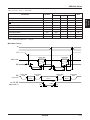
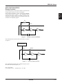
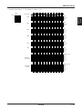
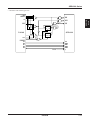
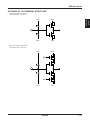
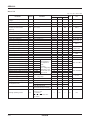
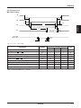
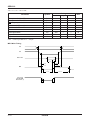
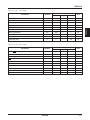
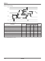
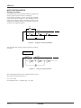
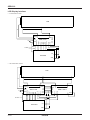
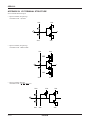
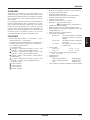
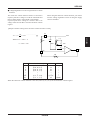
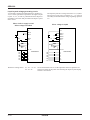
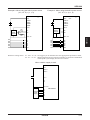
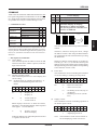
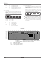
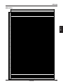
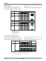
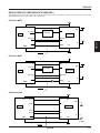
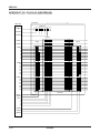
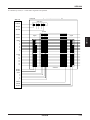
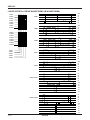
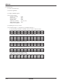
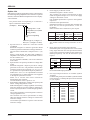
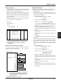
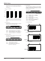
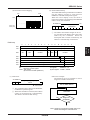
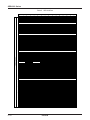
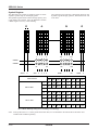
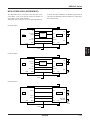
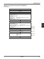
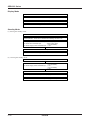
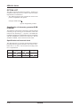
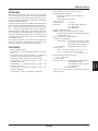
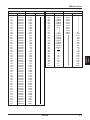
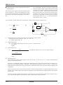
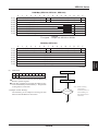
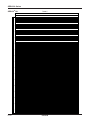
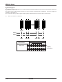
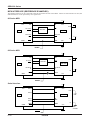
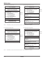
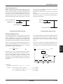
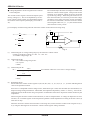
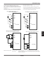
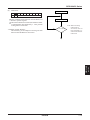
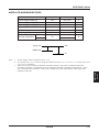
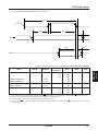
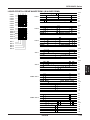
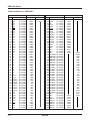
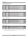
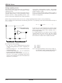
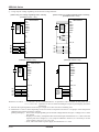
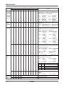
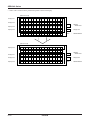
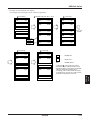
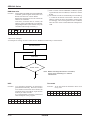
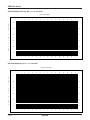
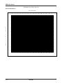
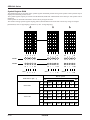
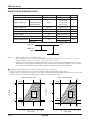
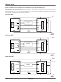
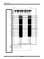
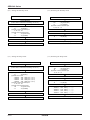
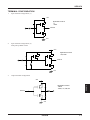
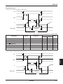
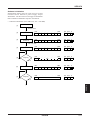
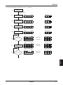
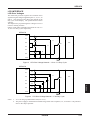
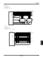
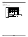
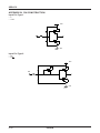
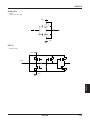
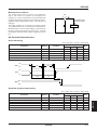
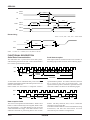
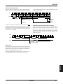
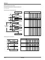
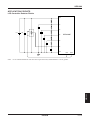
2 Using only the voltage regulating circuit and the voltage follower.
[When using no V5 voltage regulating built-in resistor]
(Example of VSS2 = VSS)
SED124XDXX
VSS
VSS2
CAP1+
CAP1–
CAP2+
CAP2–
VOUT
SED124XDXX
VSS
VSS2
CAP1+
CAP1–
CAP2+
CAP2–
VOUT
External
power
supply
External
power
supply
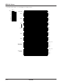
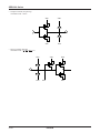
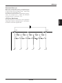
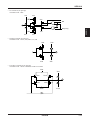
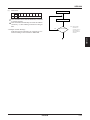
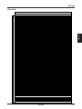
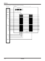
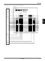
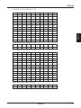
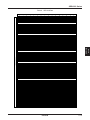
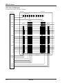
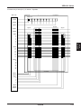
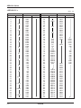
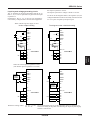
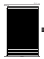
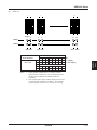
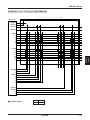
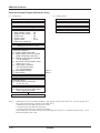
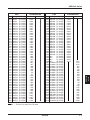
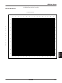
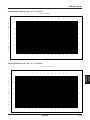
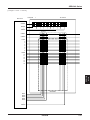
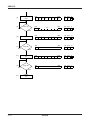
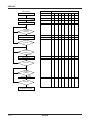
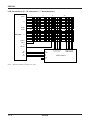
[When using a V5 voltage regulating built-in resistor]
(Example of VSS2 = VSS)
R3
V5
VR
V5
VR
R2
R1
VDD, V0
VDD, V0
C2
C2
C2
C2
C2
C2
C2
C2
C2
C2
V1
V2
V3
V4
V5
VS1
V1
V2
V3
V4
V5
VS1
C2
C2
C2
C2
C2
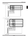
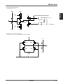
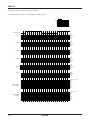
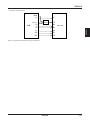
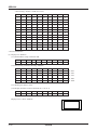
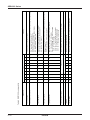
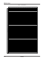
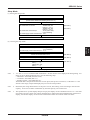
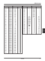
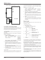
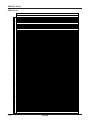
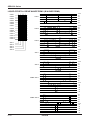
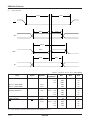
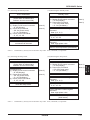
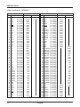
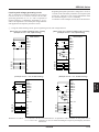
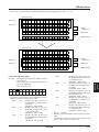
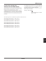
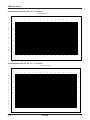
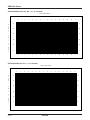
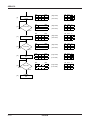
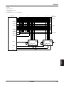
(Example of VSS2 = VSS)
SED124XDXX
VSS
VSS2
CAP1+
CAP1–
CAP2+
CAP2–
VOUT
SED124XDXX
VSS
VSS2
CAP1+
CAP1–
CAP2+
CAP2–
VOUT
V5
VR
VR
VDD, V0
VDD, V0
V1
V2
V3
V4
V5
VS1
V1
V2
V3
V4
V5
VS1
External
power
supply
External
power
supply
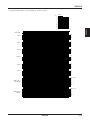
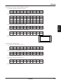
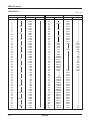
(Example of VSS2 = VSS)
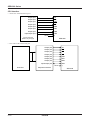
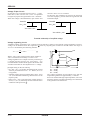
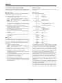
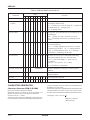
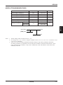
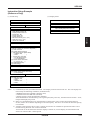
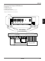
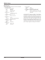
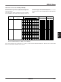
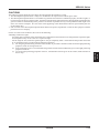
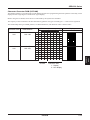
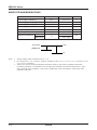
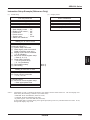
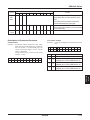
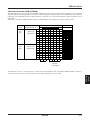
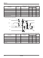
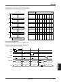
Reference set values: C1: 0.47 to 4.7 µF It is recommended to set optimum values suitable for the panel size in
C2: 0.1 to 4.7 µF capacitors C1 and C2 while watching the liquid crystal display and drive
waveforms.
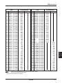
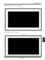
*1 Because the input impedance of the VR pin is high, use a short wire and a shielding wire.
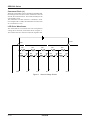
*2 Determine C1 and C2 values depending on the size of the LCD panel to be driven. Set proper values that permit
stabilizing the liquid crystal drive voltages.
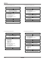
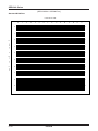
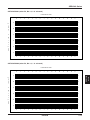
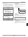
[Setting example] • Turn on the voltage regulating circuit and the voltage follower and give a voltage to VOUT from
the outside.
• Display a LCD heavy load pattern like horizontal stripes and determine a C2 value so that the
liquid crystal drive voltages (V1 to V5) may be stabilized. However, it is necessary to set the
same capacity value in C2 in every case.
• Next, turn on the built-in power supply and determine a C1 value.
8–20
EPSON