1
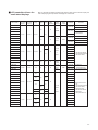
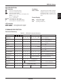
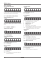
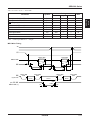
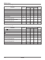
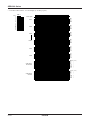
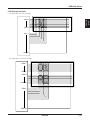
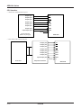
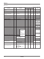
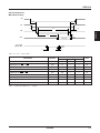
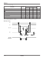
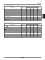
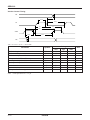
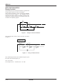
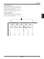
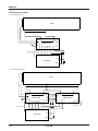
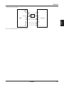
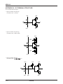
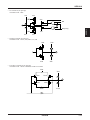
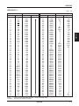
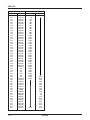
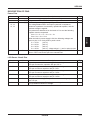
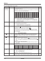
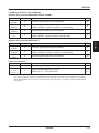
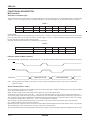
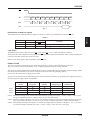
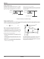
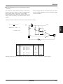
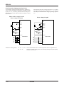
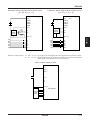
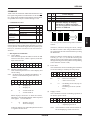
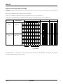
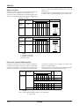
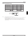
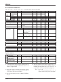
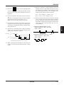
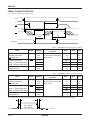
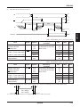
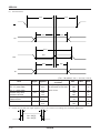
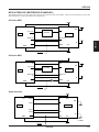
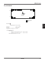
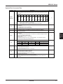
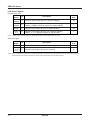
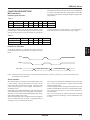
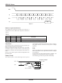
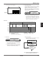
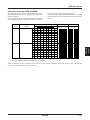
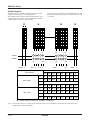
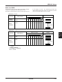
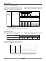
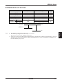
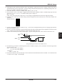
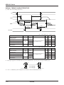
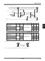
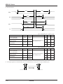
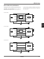
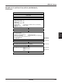
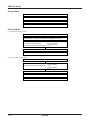
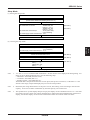
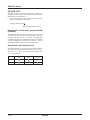
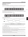
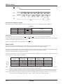
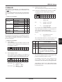
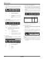
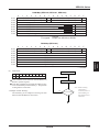
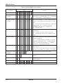
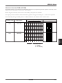
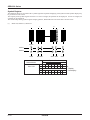
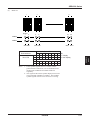
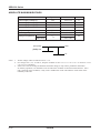
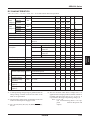
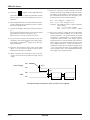
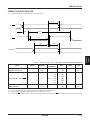
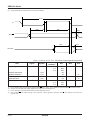
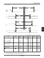
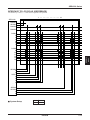
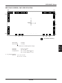
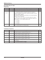
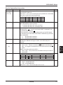
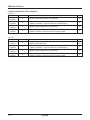
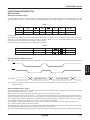
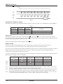
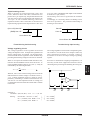
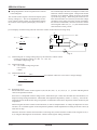
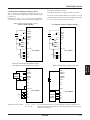
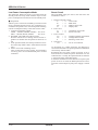
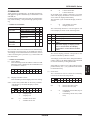
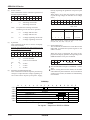
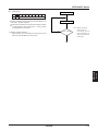
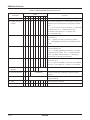
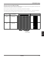
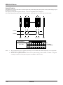
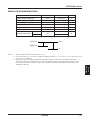
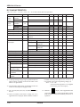
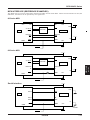
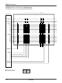
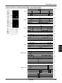
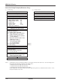
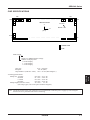
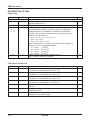
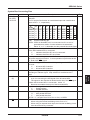
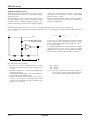
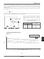
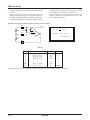
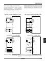
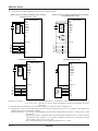
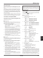
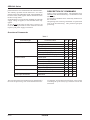
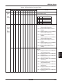
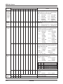
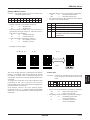
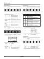
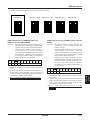
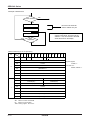
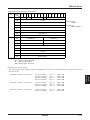
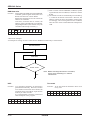
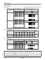
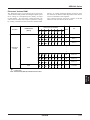
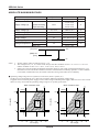
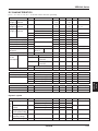
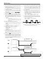
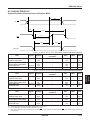
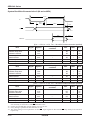
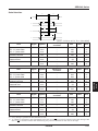
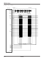
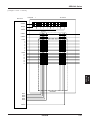
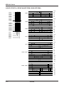
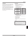
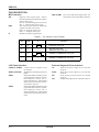
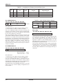
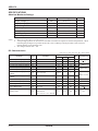
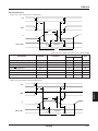
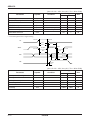
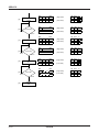
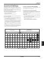
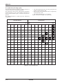
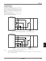
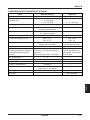
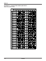
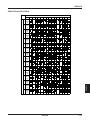
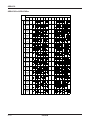
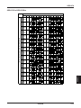
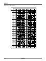
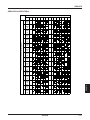
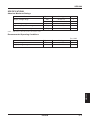
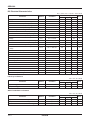
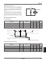
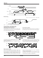
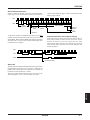
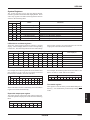
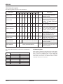
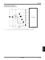
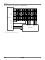
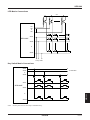
SED1220
Pins for System Bus Connection
Pin name
D7 (SI)
D6 (SCL)
D5 ~ D0
I/O
I
Description
8-bit input data bus. These pins are connected to a 8-bit or 16-bit
standard MPU data bus.
When P/S = “Low”, the D7 and D6 pins are operated as a serial data
input and a serial clock input respectively.
Q’ty
8
P/S RES I/F D7 D6 D5 D4
D3-D0
CS A0 WR
“L” —
—
SI SCL —
—
OPEN
CS A0 —
“H” “H” “H” D7 D6 D5 D4
D3-D0
CS A0
E
“H” “L” “H” D7 D6 D5 D4
D3-D0
CS A0 WR
“H” “L” “L” D7 D6 D5 D4
OPEN
CS A0 WR
RES: Indicates the active potential.
OPEN:Though “OPEN” is available, fixing the potential is
recommended for noise-withstnading characteristical reason.
—:
Indicates that it can be set at either “H” or “L”, but fixing the
potential is required.
A0
I
RES
I
CS
I
WR
I
(E)
P/S
I
Usually, this pin connects the least significant bit of the MPU address
bus and identifies a data command.
0 : Indicates that D0 to D7 are a command.
1 : Indicates that D0 to D7 are display data.
In case of a 68 series MPU, initialization can be performed by
changing RES
. In case of an 80 series MPU,
initialization can be performed by changing
.
A reset operation is performed by edge sensing of the RES signal.
An interface type for the 68/80 series MPU is selected by input level
after initialization.
“L” : 68 series MPU interface
“H” : 80 series MPU interface
Chip select signal. Usually, this pin inputs the signal obtained by
decoding an address bus signal. At the “Low” level, this pin is
enabled.
<When connecting an 80 series MPU>
Active “Low”. This pin connects the WR signal of the 80 series
MPU. The signal on the data bus is fetched at the rise of the WR
signal.
<When connecting a 68 series MPU>
Active “High”. This pin becomes an enable clock input of the 68
series MPU.
This pin switches between serial data input and parallel data input.
P/S
“High”
“Low”
4–12
IF
I
CK
I
Chip Select Data/Command
CS
A0
CS
A0
Data
D0~D7
SI
1
1
1
1
Serial Clock
–
SCL
Interface data length select pin for parallel data input.
“High”: 8-bit parallel input
“Low”: 4-bit parallel input
When P/S = “Low”, connect this pin to VDD or VSS.
External input terminal
It must be fixed to “High” when the internal oscillation circuit is used.
EPSON
1
1
1