1
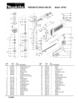
4. 1998.
•
•
•
This service manual is complied for repairing service of DOMESTIC SEWING MACHINE.
BL6200, 6700
PS1000, 1250, 1800, 1950, 2000, 2100
STAR 10, 15, 20, 20E, 30E, 40E
MYSTAR 15
Use this manual with Parts Catalogue for fault findings when you make a repair.
This machine is manufactured based on up-to-date product specifications at the time of this issue, but
there may be changes of specifications for improvements.
Contact manufacturer or local sales company for such changes.
Brother industries, Ltd.
Nagoya, Japan
CONTENTS
I.
II.
III.
IV.
PRINCIPAL MECHANISMS ......................................................................... 1
TROUBLES AND CHECK POINTS ............................................................. 11
HOW TO ADJUST THE ELEMENTS ........................................................... 21
HOW TO CHANGE THE PARTS ................................................................. 58
1.
2.
3.
4.
Always use rubber gloves when handling a printed circuit board, and do not touch the metal portion of the
printed circuit board with bare hands.
Keep the human body earthed to avoid generating static electricity.
Pack a printed circuit board with aluminum foil and avoid impact with it while storing or transporting.
Do not touch or damage the metal portion of a printed circuit board with a screwdriver or any other tool
during repairing.
-2-
I. 1.
1.
2.
3.
3.
4.
MECHANICAL CHART (B338, B346, B347, B348) .............................. 2
MECHANICAL CHART (B341, B349, B351, B352) .............................. 3
POWER TRANSMISSION CHART ...................................................... 4
DISPLAY SYSTEM BY MICRO-COMPUTER ...................................... 8
DISPLAY SYSTEM BY MICRO-COMPUTER ...................................... 9
MAIN MOTOR CONTROLLED BY MICRO-COMPUTER .................... 10
-1-
1. MECHANICAL CHART (B338 ⋅ B346 ⋅ B347 ⋅ B348)
* This part is not installed on the B346 since it is a 4-step BH model.
-2-
1. MECHANICAL CHART (B341 ⋅ B349 ⋅ B351 ⋅ B352)
* These parts are not installed on the B341, B351 and B352 since they are LCD models.
-3-
2. POWER TRANSMISSION CHART
(A) Generating mechanism of needle bar, thread take-up lever and zigzag movements
(B338 ⋅ B346 ⋅ B347 ⋅ B348)
Thread take-up
lever
Eccentric
counter weight
Upper shaft
Worm gear
Needle bar
crank rod
Pattern cam
Needle bar
clamp
Needle bar
Needle bar
supporter
Zigzag connecting
rod assembly
Z finger
Selecting cam
Needle
-4-
Pulley
(A) Generating mechanism of needle bar, thread take-up lever and zigzag movements
(B341 ⋅ B349 ⋅ B351 ⋅ B352)
Thread takeup lever
Eccentric
counter weight
Upper shaft
Worm gear
Pulley
Needle bar
crank rod
Pattern cam
Needle bar
clamp
Needle bar
Needle bar
supporter
Zigzag connecting
rod assembly
Z finger
Needle
-5-
Selecting cam
(B) Mechanism of feed dog and oscillating hook movement
Feed pattern
cam
Feed finger
Feed dog
Feed regulator
Horizontal feed cam
Worm gear
Forked
connecting rod
Pulley
Motor belt
Timing belt
Outer
rotary hook
assembly
Feed bar
Lower shaft
gear
Vertical feed
cam
Horizontal
feed plate
* Rotary shatter
Horizontal
feed shaft
Horizontal
feed arm
Lower shaft
Drop lever
* These parts are not installed on the B338, B346, B347 and B348.
-6-
Motor
Timing pulley D
(C) Automatic 1-step BH mechanism (B338 ⋅ B341 ⋅ B347 ⋅ B348 ⋅ B349 ⋅ B351 ⋅ B352)
BH change
shaft
BH change
arm
BH stopper
BH Iever
Feed control
cam (BH)
BHF finger
assembly
BH cam
BHF finger
assembly
2-(A)
BH foot
-7-
2-(B)
3. DISPLAY SYSTEM BY MICRO-COMPUTER (B341 ⋅ B351)
An 8 bit micro-computer in models installed with an LCD (liquid crystal display) regulates the LCD controller
driver which controls the information shown on the display.
<1 LINE DISPLAY SYSTEM BLOCK CHART>
LCD panel
Power supply
circuit and
motor control
circuit
Motor control
P.C. board
LCD unit
LCD controller
driver
(SED1278)
Contrast
volume
8-bit MCU
(M38004M8)
Message key
Pattern
sensor
BH Iever
SW
-8-
Bobbin winder
SW
3. DISPLAY SYSTEM BY MICRO-COMPUTER (B352)
An 8 bit micro-computer in models installed with an LCD (liquid crystal display) regulates the LCD controller
driver which controls the information shown on the display.
<4 LINE DISPLAY SYSTEM BLOCK CHART>
LCD panel
LCD
controller
driver
(NJU6426F)
LCD
segment
driver
(NJU6417F)
LCD unit
Power supply
circuit and
motor control
circuit
Motor control
P.C. board
LCD control
P.C. board
Contrast
volume
ROM
(HN62302BF)
8-bit MCU
( M38002SFP)
A, B, ↓,↑
keys
EEPROM
(X24C00P)
Pattern sensor
-9-
BH Iever
SW
Bobbin winder
SW
4. MAIN MOTOR CONTROLLED BY MICRO-COMPUTER (B341 ⋅ B349 ⋅ B351
⋅ B352)
The sewing machine’s main motor requires a constant rotation at all speeds regardless of the changes in the
load, power supply or temperature. In addition, to make the machine easy to use, it should take into account
that the machine should run slowly when it starts and the needle should be in the up position when it stops.
To execute these requirements, the main motors of these sewing machines are controlled by a microcomputer.
<MOTOR CONTROL BLOCK CHART>
Reset circuit
NP sensor
Speed volume
Drive circuit
CPU
Foot controller
SS Switch
Speed sensor
30pins
Bobbin winder
sw
Reverse sw
- 10 -
Motor
II. 1.
2.
3.
4.
5.
6.
7.
8.
9.
10.
11.
12.
13.
14.
15.
16.
17.
18.
19.
20.
21.
22.
23.
24.
25.
26.
27.
Machine skips stitches. ........................................................................ 13
Fabric does not feed. ........................................................................... 13
Fabric does not feed straight. .............................................................. 13
Upper thread breaks at start. ............................................................... 13
Upper thread breaks during sewing. .................................................... 13
Upper thread breaks during reverse sewing. ....................................... 13
Lower thread breaks. ........................................................................... 13
Needle breaks. .................................................................................... 14
Noise ................................................................................................... 14
Forward and reverse feedings differ. ................................................... 14
Improper length of buttonhole legs. ..................................................... 14
Improper buttonhole size against button size. ...................................... 14
Unbalanced patterns. ........................................................................... 14
Needle hits needle plate when pattern selector dial is turned. ............. 14
Fabric gathers. ..................................................................................... 14
The stitch shown in the pattern indication window is
different from the one being sewn. ....................................................... 14
No characters appear on the LCD. ...................................................... 15
The message keys do not work. .......................................................... 15
The LCD contrast cannot be adjusted. ................................................ 15
The wrong pattern name appears on the LCD. .................................... 15
The "Bobbin Winding" message continues to appear on the LCD. ...... 16
The "Bobbin Winding" message does not appear on the LCD
when the machine is set for bobbin winding.(1 line LCD) ..................... 16
Message "Bobbin Winding Selected" does not appear
when bobbin winding is set. (4 line LCD). ............................................ 16
Message "Lower BH Lever" does not appear when buttonhole is
set and buttonhole lever is not lowered. (1 line LCD). .......................... 16
Message "Lower Buttonhole Lever" does not appear when buttonhole is
set and buttonhole lever is not lowered. (4 line LCD). .......................... 16
Message "Lower BH Lever" appears when buttonhole
lever is lowered. ................................................................................... 17
The light does not turn on even after the power is turned on. .............. 17
- 11 -
28. The motor does not run. ...................................................................... 18
29. The motor does not run smoothly or it does not run
at a high speed. ................................................................................... 18
30. Even after the machine is started, it stops suddenly. ........................... 18
31. The speed at which the machine operates cannot be adjusted. .......... 19
32. The needle does not stop in the up position. ....................................... 19
33. The machine does not operate if the reverse sewing button is
pressed or does not operate at a slow speed if the button is
pressed while the machine is running. ................................................. 19
34. The machine stops immediately after bobbin winding is started. ......... 20
35. The machine does not operate when the foot controller is
depressed. ........................................................................................... 20
- 12 -
PROBLEM
1.
Machine skips
stitches.
CAUSE
1.
2.
3.
4.
5.
6.
7.
8.
CORRECTION
Improper setting of the needle.
Bent or blunt needle.
Improper threading.
Improper combination of needle/
thread/fabric.
Stretch fabric is used.
Improper timing of the needle and
rotary hook.
Improper height of the needle bar.
Improper clearance between the needle
and rotary hook.
Set the needle correctly.
Change the needle.
Reset threading correctly.
Select correct combination of needle/
thread/fabric.
Use stretch fabric needle, optional stretch
presser foot.
Refer to P.28.
Refer to P.29.
Refer to P.28.
2.
Fabric does not
feed.
1.
2.
3.
4.
5.
Stitch length is set at "O".
Improper height of feed dog.
Thick fabric.
Feed dog is worn out.
The feed dog is lowered.
Set proper stitch length.
Refer to P.32.
Change the fabric.
Change the feed dog.
Raise the feed dog with the drop lever.
3.
Fabric does not
feed straight.
1.
Uneven pressure on right/left side of
presser foot
Change the presser foot and the feed dog.
4.
Upper thread
breaks at start.
1.
Improper threading.
Thread correctly.
5.
Upper thread
breaks during
sewing.
1.
2.
3.
4.
5.
6.
7.
8.
9.
Bent or blunt needle.
Improper setting of needle.
Thread tension is too tight.
Thread is tangled.
Inferior needle eye.
Inferior needle slot of needle plate.
Inferior upper thread path.
Inferior thread.
Needle hits needle plate or outer rotary
hook.
Change the needle.
Set the needle correctly.
Adjust tension control dial correctly.
Thread correctly.
Change the needle.
Change the needle plate.
Clean or replace.
Check or change the thread.
Set the needle bar and outer rotary hook
correctly.
* Refer to P.28.
Change inner rotary hook.
10. There are scratches on inner rotary
hook.
6.
Upper thread
breaks during
reverse sewing.
1.
2.
Fabric is pulled excessively.
Improper use of reverse sewing button.
Guide the fabric.
Push reverse sewing button as far as it will
allow.
7.
Lower thread
breaks.
1.
Lower thread tension is too tight.
2.
Too much thread is wound on bobbin.
3.
4.
Thread is tangled.
Bobbin does not turn in inner rotary
hook.
Inferior thread.
Adjust the tension by loosening the tension
spring. screw on inner rotary hook.
Change to other bobbin or adjust bobbin
winder.
Thread correctly.
Change the bobbin.
5.
- 13 -
Check or change the thread.
PROBLEM
8.
Needle breaks.
CAUSE
1.
CORRECTION
2.
Touch pattern dial while needle is in
the fabric.
Needle hits inner rotary hook.
3.
Needle hits needle plate.
4.
5.
7.
8.
Bent or blunt needle.
Improper clearance between the needle
and the outer rotary hook.
Machine feeds while needle is in the
fabric.
Needle flows.
Fabric is pulled excessively.
1.
2.
3.
4.
Play of worm/pattern cam gear.
Play of lower shaft.
Play of upper shaft.
Noise from rotary hook.
Adjust to proper gearing.
Adjust play of the lower shaft.
Adjust play of the upper shaft.
Clean the race of inner rotary hook and
outer rotary hook or replace inner rotary
hook.
10. Forward and
reverse feedings
differ.
11. Improper length of
buttonhole legs.
1.
Improper adjustment of revers sewing
lever.
Refer to P.46.
1.
Improper adjustment.
Adjust screw.
* Refer to P.42.
12. Improper
buttonhole size
against button size.
1.
Improper adjustment of buttonhole
length.
Adjust the length of buttonhole.
* Refer to P.44.
13. Unbalanced
patterns.
1.
2.
Stitch length dial is not set at ’’4’’.
Feed dog is worn out.
3.
4.
5.
6.
Improper height of feed dog.
Improper attachment of feed dog.
Forward and reverse feedings differ.
Stitch width dial is not set to "5".
Operate machine correctly.
Change the feed dog.
* Refer to P.31, P.32.
Refer to P.32.
Attach the feed dog correctly.
Refer to P.40.
Operate machine correctly.
14. Needle hits needle
plate when pattern
selector dial is
turned.
1.
Release volume is too big.
Adjust the release volume.
* Refer to P.37.
15. Fabric gathers.
1.
2.
3.
Thread tension is too tight.
Blunt needle.
Improper combination of needle/
thread/fabric.
Improper threading.
Reduce the tension.
Change the needle.
Select correct combination of needle/
thread/fabric.
Reset threading correctly.
Release volume is too small.
The indicate gear and pattern indicator
plate are not aligned correctly.
Adjust the release volume.
* Refer to P.37.
Adjust the pattern indicator.
* Refer to P.36.
6.
9.
Noise.
4.
16. The stitch shown in
the pattern
indication window
is different from
the one being
sewn.
1.
2.
- 14 -
Operate machine correctly.
Adjust the position of inner rotary hook
stopper.
* Refer to P.30.
Make sure the correct needle is used.
* Refer to P.27, P.37.
Change needle.
Refer to P.28.
Refer to P.25, P.26.
Refer to P.27.
Guide the fabric.
PROBLEM
17. No characters
appear on the
LCD.
1.
2.
3.
4.
CAUSE
CORRECTION
1 line LCD
1 line LCD
Improper setting of LCD contrast key.
Disconnection of connector CN 1.
Voltage between terminal 2-1 of LW1
on motor control unit is less than
DC5V.
Inferior LCD unit.
4 line LCD
1.
2.
3.
4.
5.
18. The message keys
do not work.
Improper setting of LCD contrast
manual.
Disconnection of connector P1.
Disconnection of connector P5.
Voltage between terminal 2-1 of LW1
on motor control unit is less than
DC5V.
Inferior LCD control PCB or LCD
module.
19. The LCD contrast
cannot be adjusted.
Message key top does not work.
Inferior LCD unit.
Each key tops do not work.
Inferior LCD control PCB.
1 line LCD
1.
2.
LCD contrast key does not work.
Improper LCD contrast.
4 line LCD
1.
2.
20. The wrong pattern
name appears on
the LCD.
2.
LCD contrast key does not work.
Improper LCD control PCB.
2.
Replace the LCD control PCB or LCD
module.
Check the message key and key top.
Replace the LCD unit.
4 line LCD (A,B,↓,↑)
Check each keys and key tops.
Replace the LCD control PCB.
1 line LCD
Check the slide volume and slide key.
Replace the LCD unit.
Check the slide volume and slide key.
Replace the LCD control PCB.
1 line LCD
Disconnection of connector CN2 on
LCD unit.
Inferior LCD unit or pattern sensor.
4 line LCD
1.
Connect P1 on LCD control PCB.
Connect P5 on LCD module.
Replace the motor control unit.
4 line LCD
1 line LCD
1.
Adjust LCD contrast manual.
1 line LCD
4 line LCD (A,B,↓,↑)
1.
2.
Replace the LCD unit.
4 line LCD
1 line LCD
1.
2.
Adjust LCD contrast key.
Connect CN1 on LCD unit.
Replace the motor control unit.
Connect CN2 on LCD unit.
Replace the LCD unit or pattern sensor.
4 line LCD
Disconnection of connector P3 on LCD
control PCB.
Inferior LCD control PCB or pattern
sensor.
- 15 -
Connect P3 on LCD control PCB.
Replace the LCD control PCB or pattern
sensor.
PROBLEM
CAUSE
CORRECTION
21. The "Bobbin
Winding" message
continues to appear
on the LCD.
1 line LCD
1 line LCD
1.
BW switch does not work.
2.
Inferior BW switch.
3.
Inferior LCD unit.
4 line LCD
22. The "Bobbin
Winding" message
does not appear on
the LCD when the
machine is set for
bobbin winding.
(1 line LCD).
23. Message "Bobbin
Winding Selected"
does not appear
when bobbin
winding is set.
(4 line LCD)
24. Message "Lower
BH Lever" does
not appear when
buttonhole is set
and buttonhole
lever is not
lowered. (1 line
LCD)
25. Message "Lower
Buttonhole Lever"
does not appear
when buttonhole is
set and buttonhole
lever is not
lowered.
(4 line LCD)
Adjust the BW stitch.
*Refer to P.51.
Replace the BW switch.
*Refer to P.51.
Replace the LCD unit.
4 line LCD
1.
2.
3.
BW switch does not work.
Inferior BW switch.
Inferior LCD control PCB.
Adjust the BW stitch.
*Refer to P.51.
Replace the BW switch.
*Refer to P.51.
Replace the LCD control PCB.
1.
Connect CN1 on LCD unit.
3.
Disconnection of connector CN1 on
LCD unit.
Disconnection of connector CN5 on
Motor control unit.
BW switch does not work.
4.
Inferior BW switch.
5.
Inferior LCD unit.
1.
3.
Disconnection of connector P1 on LCD
control PCB.
Disconnection of connector CN5 on
Motor control unit.
BW switch does not work.
4.
Inferior BW switch.
5.
Inferior LCD control PCB.
1.
3.
Disconnection of connector CN3 on
LCD unit.
Disconnection of connector CN7 on
Motor control unit.
BH lever switch does not work.
4.
Inferior BH lever switch.
5.
Inferior LCD unit.
1.
3.
Disconnection of connector P2 on LCD
control PCB.
Disconnection of connector CN7 on
Motor control unit.
BH lever switch does not work.
4.
Inferior BH lever switch.
5.
Inferior LCD control PCB.
2.
2.
2.
2.
- 16 -
Connect CN5 on Motor control unit
Adjust the BW stitch.
*Refer to P.51.
Replace the BW switch.
*Refer to P.51.
Replace the LCD unit.
Connect the P1 on LCD control PCB.
Connect the CN5 on Motor control unit.
Adjust the BW switch.
*Refer to P.51.
Replace the BW switch.
*Refer to P.51.
Replace the LCD control PCB.
Connect the CN3 on LCD unit.
Connect the CN7 on Motor control unit.
Adjust the BH lever switch.
*Refer to P.49.
Replace the BH lever switch.
*Refer to P.49.
Replace the LCD unit.
Connect the P2 on LCD control PCB.
Connect the CN7 on Motor control unit.
Adjust the BH lever switch.
*Refer to P.49.
Replace the BH lever switch.
*Refer to P.49.
Replace the LCD control PCB.
PROBLEM
CAUSE
CORRECTION
26. Message "Lower
BH Lever" appears
when button-hole
lever is lowered.
1 line LCD
1 line LCD
1.
BH lever switch does not work.
2.
Inferior BH lever switch
3.
Inferior LCD unit
4 line LCD
27. The light does not
turn on even after
the power is turned
on.
4 line LCD
1.
BH lever switch does not work.
2.
Inferior BH lever switch
3.
Inferior LCD control PCB
1.
The voltage on both ends of connector
CN1 is not 100 V AC when the AC
cord is inserted.
The resistance on both ends of the
power switch is not less than 1 Ω when
the power is turned on.*
The fuse is broken.
The light does not turn on. (The light
may be damaged or deteriorating or it
may have a bad connection.) Remove
the light and measure the resistance on
both ends. It should be less than 3 Ω.*
The output from the transformer is
incorrect. When connector CN4 is
disconnected from the motor control
unit and the power is turned on, the
voltage between pins 1 and 2 of
connector CN4 should be
approximately 10V AC.
Other causes.
2.
3.
4.
5.
6.
Adjust the BH lever switch.
*Refer to P.49.
Replace the BH lever switch.
*Refer to P.49.
Replace the LCD unit.
Adjust the BH lever switch.
*Refer to P.49.
Replace the BH lever switch.
*Refer to P.49.
Replace the LCD control PCB.
Replace either the AC cord or the motor
control unit.
Replace the motor control unit.
Replace the motor control unit.
Replace the light.
Replace the motor control unit.
Replace the motor control unit.
* Be sure to turn off the power and remove from the PCB the connector.
- 17 -
PROBLEM
28. The motor does not
run.
CAUSE
1.
The pulley is turned too tightly.
2.
The resistance between the two ends of
motor connector CN2 is not between
25 and 35 Ω.*
Inferior SS switch. The resistance
between pins 4 and 5 of the SS-VR
PCB unit connector should be less than
1 Ω when the SS switch is turned on
and Ω when the SS switch is turned
off.*
Inferior BT switch. The resistance
between pins 1 and 2 of connector CN6
(red) should be less than 1 Ω when the
BT switch is turned on and ∞ when the
BT switch is turned off.*
The resistance between pins 2 and 3 of
the pin jack assembly on the PCB
(F.C.) should not be less than 1 Ω when
the foot controller is not inserted.*
Other causes.
3.
4.
5.
6.
29. The motor does not
run smoothly or it
does not run at a
high speed.
1.
2.
3.
4.
5.
6.
7.
8.
30. Even after the
machine is started,
it stops suddenly.
CORRECTION
1.
2.
Adjust the mechanism so that the pulley
rotates easily.
Replace the motor.
Replace the SS-VR PCB unit.
Replace the BT switch.
*Refer to P.50.
Replace the motor control unit.
Replace the motor control unit.
The Pulley is sometimes easy or
sometimes difficult to move when it is
rotated by hand.
Accumulated lint or thread under the
needle plate.
Improper tension in motor belt and
timing belt.
Tight gearing of the pattern cam gear
and worm gear.
The rotary shutter is dirty.
The motor control unit is installed
incorrectly. It is loose or slanted.
The voltage between pins 2+ and 3- on
the SS-VR PCB does not stay between
0 and 5 V DC when the power is turned
on and the speed adjustor is slid to the
maximum.
Other causes.
Adjust the mechanism so that the pulley
rotates easily.
The motor control unit is installed
incorrectly. It is loose or slanted.
Other causes.
Install the motor control unit correctly.
Clean inner rotary hook, outer rotary hook
and feed dog.
Refer to P.25.
Refer to P.27.
Clean the rotary shutter.
Install the motor control unit correctly.
Replace the SS-VR PCB unit.
Replace the motor control unit.
Replace the motor control unit.
* Be sure to turn off the power and remove from the PCB the connector.
- 18 -
PROBLEM
31. The speed at which
the machine
operates cannot be
adjusted.
CAUSE
The output from the transformer is
incorrect. The voltage between pins 5
and 6 of the transformer should be
approximately 8V AC.
The voltage between the S V and GND
on the motor control unit is incorrect. It
should be 5±0.25 V DC.
The voltage between pins 2+ and 3- on
the SS-VR PCB does not stay between
0 and 5 V DC when the power is turned
on and the speed adjustor is slid to the
maximum.
Other causes.
Replace the motor control unit
Check and adjust if necessary.
*Refer to P.48.
Install the motor control unit correctly.
4.
The position of the NP sensor shutter is
incorrect.
The motor control unit is installed
incorrectly. It is loose or slanted.
Inferior BW switch.
The resistance between pins 1 and 2 of
connector CN5 (black) should be less
than 1Ω when the BW switch is turned
on and ∞ when the BW switch is
turned off.*
Other causes.
1.
The BT switch dose not work.
2.
Inferior BT switch. The resistance
between pins 1 and 2 of connector CN6
(red) should be less than 1Ω when the
BT switch is turned on and ∞ when the
BT switch is turned off.*
Other causes.
Check and adjust if necessary.
*Refer to P.50.
Replace the BT switch.
*Refer to P.50.
1.
2.
3.
4.
32. The needle does
not stop in the up
position.
1.
2.
3.
33. The machine does
not operate if the
reverse sewing
button is pressed or
does not operate at
a slow speed if the
button is pressed
while the machine
is running.
(However, the
machine does not
operate at slow
speed when the
foot controller is
being used.)
CORRECTION
3.
Replace the motor control unit.
Replace the SS-VR PCB unit.
Replace the motor control unit.
Replace the BW switch.
*Refer to P.51.
Replace the motor control unit.
Replace the motor control unit.
* Be sure to turn off the power and remove from the PCB the connector.
- 19 -
PROBLEM
34. The machine stops
immediately after
bobbin winding is
started.
CAUSE
1.
2.
35. The machine does
not operate when
the foot controller
is de pressed.
1.
2.
3.
CORRECTION
If the machine stops approx. 1 second
after bob-bin winding starts, the BW
switch is not operating correctly.*
The resistance between pins 1 and 2 of
connector CN5 (black) should be less
than 1 Ω when the BW switch is turned
on and ∞ when the BW switch is
turned off.
Other causes.
Replace the BW switch.
*Refer to P.51.
The foot controller is not operating
properly.
The resistance between the two ends of
the foot controller plug is not less than
10 KΩ.*
The resistance between pins 2 and 3 of
the pin jack assembly on the PCB
(F.C.) should be less than 1 Ω when the
foot controller is plugged in and ∞
when it is not plugged in.*
Other causes.
Replace the foot controller.
Replace the motor control unit.
Replace the motor control unit.
Replace the motor control unit.
* Be sure to turn off the power and remove from the PCB the connector.
- 20 -
III. 1.
1.
2.
3.
4.
5.
6.
7.
8.
9.
10.
11.
12.
13.
14.
15.
16.
17.
18.
19.
20.
21.
22.
23.
24.
25.
26.
27.
28.
29.
30.
31.
32.
33.
34.
35.
!
ADJUSTMENT OF EACH CONTROL UNIT (4-STEP BH MODEL) ............... 22
ADJUSTMENT OF EACH CONTROL UNIT (1-STEP BH MODEL) ............... 23
ADJUSTMENT OF THE TIMING BETWEEN THE UPPER AND LOWER SHAFTS ..... 24
TENSION ON MOTOR BELT AND TIMING BELT ......................................... 25
TIMING OF NEEDLE BAR AND FEED ........................................................... 26
POSITION OF ZIGZAG NEEDLE SWING ...................................................... 27
POSITION OF ROTARY HOOK ..................................................................... 28
HEIGHT OF NEEDLE BAR ............................................................................. 29
POSITION OF INNER ROTARY HOOK STOPPER ....................................... 30
POSITION OF FEED DOG ............................................................................. 31
HEIGHT OF FEED DOG ................................................................................. 32
HEIGHT OF PRESSER BAR .......................................................................... 33
ADJUSTMENT OF THREAD TENSION DIAL ................................................ 34
ADJUSTMENT OF AUTO TENSION .............................................................. 35
POSITION OF PATTERN INDICATION PLATE ............................................. 36
CLEARANCE BETWEEN CAM AND CAM FINGER ...................................... 37
POSITION OF CAM FINGER FOR FEED CAM AND PATTERN CAM .......... 38
SETTING OF FEED BRACKET ...................................................................... 39
FORWARD AND REVERSE SEWING FOR RICK-RACK STITCH ................ 40
ADJUSTMENT OF FEED ............................................................................... 41
BUTTONHOLE ADJUSTMENT (FORWARD AND REVERSE FEEDING) .... 42
BUTTONHOLE ADJUSTMENT (BAR TACK FEEDING) ................................ 43
BUTTONHOLE ADJUSTMENT (THE LENGTH OF THE BUTTONHOLE
AND THE PRESSURE OF THE BH LEVER) ................................................. 44
MAXIMUM STITCH WIDTH WHEN SET AT STRAIGHT (LEFT)
AND ZIGZAG STITCH .................................................................................... 45
FORWARD AND REVERSE FEEDING FOR STRAIGHT STITCH ................ 46
ADJUSTMENT OF BOBBIN WINDING .......................................................... 47
POSITION OF N.P. (NEEDLE POSITION) SHUTTER ................................... 48
ADJUSTMENT OF BH LEVER SWITCH ........................................................ 49
ADJUSTMENT OF REVERSE SEWING SWITCH ......................................... 50
ADJUSTMENT OF BOBBIN WINDING SWITCH ........................................... 51
ADJUSTMENT OF INNER ROTARY HOOK TENSION ................................. 52
NEEDLE THREADER ..................................................................................... 53
NEEDLE THREADER (CHECKING THE HOOK POSITION IN
HORIZONTAL DIRECTION) ........................................................................... 54
NEEDLE THREADER (EXCHANGE) ............................................................. 55
NEEDLE THREADER (CHECKING THE HOOK POSITION IN
VERTICAL DIRECTION) ................................................................................. 56
NEEDLE THREADER (ADJUSTMENT THE HOOK POSITION IN
VERTICAL DIRECTION) ................................................................................. 57
- 21 -
1. ADJUSTMENT OF EACH CONTROL UNIT (4-STEP BH MODEL) (B346)
- 22 -
1. ADJUSTMENT OF EACH CONTROL UNIT (1-STEP BH MODEL)
(B338 ⋅ B341 ⋅ B347 ⋅ B348 ⋅ B349 ⋅ B351 ⋅ B352)
- 23 -
2. ADJUSTMENT OF THE TIMING BETWEEN THE UPPER AND LOWER
SHAFTS
STANDARD
When the mark on the horizontal feed cam of the upper shaft is at its topmost position, the mark on timing
pulley D of the lower shaft should be at its bottommost position. (Turn pulley counterclockwise.)
ADJUSTMENT
1.
2.
3.
Remove the timing belt from the horizontal feed cam, the tension pulley and timing pulley D.
Position the mark on the horizontal feed cam so it is at its topmost position and the mark on timing pulley
D so it is at its bottommost position.
Install the timing belt onto the horizontal feed cam, the tension pulley and timing pulley D.
- 24 -
3. TENSION ON MOTOR BELT AND TIMING BELT
STANDARD
There should be 4 ~ 6 mm of slack on the motor belt, 3 ~ 4 mm of slack on timing belt, when the center of
each belt is just pushed with about 200g pressure.
ADJUSTMENT
1.
2.
3.
4.
5.
6.
Loosen two screws on the motor holder.
Adjust tension on timing belt by moving motor holder.
Tighten two screws.
Loosen the screw on tension pulley.
Adjust tension on timing belt by moving tension pulley.
Tighten the screw.
- 25 -
4. TIMING OF NEEDLE BAR AND FEED (B341 ⋅ B349 ⋅ B351 ⋅ B352)
STANDARD
When the needle bar is at its highest position, the mark on the horizontal feed cam should be at its topmost
position.
(Horizontal feed should start when needle bar reaches at the position of -7 ~ -17° from its highest position.)
(Turn the pulley counterclockwise.)
ADJUSTMENT
1.
2.
3.
4.
5.
6.
7.
8.
Set pattern dial to straight stitch and stitch length to "4".
Loosen two screws on eccentric counter weight.
Adjust the eccentric counter weight so the needle is at its highest point when the mark on the horizontal
feed cam of the upper shaft is at its topmost position.
Tighten two screws.
Make sure that timing was adjusted correctly by turning the pulley counterclockwise.
Loosen two screws of thread control cam.
Fit the both marks of thread control cam and eccentric counter weight by turning the thread control cam.
Tighten two screws.
- 26 -
5. POSITION OF ZIGZAG NEEDLE SWING
STANDARD
Set pattern dial to zigzag stitch.
The needle should drop in the needle hole balanced.
When the zigzag width dial is turned from "0" to "5" while the needle is in the right position, horizontal
movement of the needle should be less than 0.1 mm.
Needle swing on the way up from lowest position to needle plate should be less than 0.15 mm and that on
the way down from needle plate to lowest position should be less than 0.05 mm.
ADJUSTMENT
1.
2.
3.
Set pattern dial to zigzag stitch.
Loosen the zigzag gear lever fixing screw.
Move the zigzag connecting rod to its lowest position (where the roller of zigzag connecting rod contacts
unit base F) while keeping the zigzag width dial at the minimum, "0", and while preventing backlash in
the gear.
4. Tighten the screw.
5. Set zigzag width dial to "5" and set the right position of needle by turning the pulley.
6. Turn zigzag width dial from "0" to "5" and adjust eccentric nut so that the needle does not swing.
7. Set zigzag width dial to "5" and adjust eccentric nut so that the needle drops in the needle hole balanced.
8. Loosen three set screws on worm gear.
9. Adjust needle swing by turning worm gear.
10. Tighten three screws.
NOTE
Make sure that there is no clearance between worm gear and pattern cam gear.
- 27 -
6. POSITION OF ROTARY HOOK
STANDARD
When pattern dial is set to zigzag stitch, zigzag width dial is set to "5" (the needle is at the left side) and
needle raises from its lowest position by 2.75 ~ 3.15 mm, the pointed end of rotary hook should meet with
right side of needle.
Under this condition, clearance between the hook and the needle should be less than 0.1 mm and the hook
should not hit the needle.
ADJUSTMENT
1.
2.
3.
4.
5.
Set pattern dial to zigzag stitch and zigzag width dial to "5". (the needle is at the left side)
Loosen three screws on lower shaft gear.
Adjust position of rotary hook. (When needle raises from its lowest position by 2.75 ~ 3.15 mm, the
pointed end of rotary hook should meet with right side of the needle.)
Tighten three screws.
Adjust clearance by turning clearance adjusting eccentric screw.
- 28 -
7. HEIGHT OF NEEDLE BAR
STANDARD
When pattern dial is set to the zigzag stitch, the zigzag width dial is set to "5" (the needle is at the left side)
and the pointed end of the rotary hook contacts the right side of the needle, the clearance between the top of
the needle eye and the hook point should be 0.8 ~ 1.2 mm.
ADJUSTMENT
1.
2.
3.
4.
5.
Set pattern dial to zigzag stitch and zigzag width dial to "5". (the needle is at the left side)
Set position so that hook point meet with right side of the needle by turning the pulley.
Loosen the screw on needle bar holder.
Adjust height of needle clamp.
Tighten the screw.
- 29 -
8. POSITION OF INNER ROTARY HOOK STOPPER
STANDARD
Inner rotary hook stopper should hold inner rotary hook by 1.9 ~ 2.1 mm as shown in drawing.
ADJUSTMENT
1.
2.
3.
Loosen the screw on inner rotary hook stopper.
Adjust the position of inner rotary hook stopper.
(Face A on inner rotary hook and feed direction should be at right angles.)
Tighten the screw.
- 30 -
9. POSITION OF FEED DOG
STANDARD
When the upper shaft is rotated once with the maximum feed, the feed dog should not contact the needle
plate on the left and right. When the feed dog is in its initial feed position (as far forward as possible), the
clearances between the feed dog and the needle plate should be 0.3 ~ 0.8 mm.
ADJUSTMENT
1.
2.
3.
4.
5.
6.
7.
Loosen two screws on the horizontal feed plate.
Adjust the left and right sides of the feed dog.
Tighten two screws.
Turn the pulley to move the feed dog to its initial feed position.
Loosen the screw on the horizontal feed arm.
Adjust the arm so the clearance between the feed dog and the needle plate is between 0.3 ~ 0.8 mm.
Tighten the screw.
- 31 -
10. HEIGHT OF FEED DOG
STANDARD
Feed dog should be higher than the needle plate by 0.9 ~ 1.1 mm when the feed dog is raised to its highest
position.
ADJUSTMENT
1.
2.
3.
4.
Raise the feed dog using the drop lever, then raise the feed dog to its highest position by turning the
pulley.
Loosen the screw for vertical feed finger.
Adjust the height of the feed dog by turning vertical feed finger.
Tighten the screw.
- 32 -
11. HEIGHT OF PRESSER BAR
STANDARD
The clearance between presser foot and needle plate should be 6.0 ~ 6.5 mm.
ADJUSTMENT
1.
2.
3.
4.
Raise presser foot.
Loosen the screw on presser bar guide bracket.
Adjust height of presser bar.
(Presser foot should be parallel to feed dog.)
Tighten the screw.
(B341 ⋅ B349 ⋅ B351 ⋅ B352)
(B338 ⋅ B346 ⋅ B347 ⋅ B348)
- 33 -
12. ADJUSTMENT OF THREAD TENSION DIAL
(B341 ⋅ B349 ⋅ B351 ⋅ B352)
STANDARD
When thread tension dial is set to "AUTO" and presser foot is lowered, upper thread tension should be 10 ~
13g using polyester thread #60.
ADJUSTMENT
1.
2.
3.
4.
Set thread tension dial to "AUTO", put polyester thread between tension discs and lower presser foot.
Loosen the screw for thread tension control screw.
Measure thread tension using tension gauge and adjust tension to 10 ~ 13g by turning thread tension
control screw.
Tighten the screw.
(B338 ⋅ B346 ⋅ B347 ⋅ B348)
STANDARD
When thread tension dial is set to "4" and presser foot is lowered, upper thread tension should be 33 ~ 38g
using polyester thread #60.
ADJUSTMENT
1.
2.
3.
4.
Set thread tension dial to "4", put polyester thread between tension discs and lower presser foot.
Loosen the screw for thread tension control screw.
Measure thread tension using tension gauge and adjust tension to 33 ~ 38g by turning thread tension
control screw.
Tighten the screw.
- 34 -
13. ADJUSTMENT OF AUTO TENSION (B341 ⋅ B349 ⋅ B351 ⋅ B352)
(ADJUSTMENT OF ROLLER FOR THREAD TENSION CONTROL)
STANDARD
Thread polyester thread #60 between roller and thread holder.
Turn the pully counterclockwise. The thread should be locked when the top of the needle eye comes down 0
~ 1.5 mm down from the surface of needle plate.
(Remove presser foot and lower presser foot bar.)
ADJUSTMENT
1.
2.
3.
4.
5.
Set pattern dial to straight stitch and lower the presser foot after threading polyester thread #60 properly.
Turn the pulley counterclockwise and adjust needle position at the top of needle eye 0 ~ 1.5 mm down
from the surface of needle plate.
Loosen the screw for roller adjusting shaft.
Turn the roller adjusting shaft by screw driver and adjust the roller position in between lock and release
condition with drawing thread.
(Adjust the roller so it is within one cycle of the roller adjusting shaft.)
Tighten the screw.
NOTE
Turn the pulley counterclockwise 2 ~ 3 times. Check if the roller should lock thread when top of needle eye 0
~ 1.5 mm down from the surface of needle plate. Also check if thread tension is proper on 2 pcs of broad with
needle #14(No. 90), polyester thread #60.
- 35 -
14. POSITION OF PATTERN INDICATION PLATE
(B338 ⋅ B346 ⋅ B347 ⋅ B348 ⋅ B349)
STANDARD
Each pattern on indication plate should be indicated at the center of the indication window.
ADJUSTMENT
1.
2.
3.
4.
Set pattern dial to zigzag stitch and check baseline on selecting cam which should meet with upper end
of release lever.
Loosen two screws on indication gear.
Set the symbol of zigzag stitch at the center of the indication window by turning indication gear.
Tighten two screws.
NOTE
After adjustment, make sure each pattern is indicated at the center of the indication window by turning
pattern dial.
- 36 -
15. CLEARANCE BETWEEN CAM AND CAM FINGER
STANDARD
When pattern dial is set to rick-rack stitch and cam finger is released, clearance between cam finger and
pattern cam & feed cam should be 0.3 ~ 0.5 mm.
ADJUSTMENT
1.
2.
3.
4.
Set pattern dial to rick-rack stitch and release cam finger from pattern and feed cam.
Loosen the nut to release adjustment screw.
Adjust clearance by turning release adjustment screw.
Tighten the nut.
- 37 -
16. POSITION OF CAM FINGER FOR FEED CAM AND PATTERN CAM
STANDARD
Feed cam finger and zigzag cam finger should be center position of each cam.
ADJUSTMENT
1.
2.
3.
4.
5.
Check the position of feed cam finger and zigzag cam finger by turning pattern dial.
Loosen the screw on selecting lever holder.
Set the Z cam finger and F cam finger to the center position of each cam by adjust selecting lever holder.
Tighten the screw.
Make sure cam finger is located at the center position of each cam by turning pattern dial.
• The shape of the cams on the B346 differ slightly.
- 38 -
17. SETTING OF FEED BRACKET
STANDARD
When stitch length dial is set to "0", each mark on feed dial gear, feed gear, feed cam and feed finger should
meet in line.
ADJUSTMENT
1.
2.
3.
4.
5.
Set stitch length dial to "0".
Set the mark on the feed cam to feed finger.
Set the mark on the feed gear to the mark on feed cam.
Set the mark on the feed dial gear to the mark on feed gear.
Fix the feed bracket by tightening two screws.
- 39 -
18. FORWARD AND REVERSE SEWING FOR RICK-RACK STITCH
STANDARD
When pattern dial is set to rick-rack stitch, there should be no difference between forward and reverse feed.
ADJUSTMENT
1.
2.
3.
4.
Set pattern dial to rick-rack stitch.
Loosen the nut for adjustment screw.
Adjust forward and reverse feeding by turning screw.
Tighten the nut.
- 40 -
19. ADJUSTMENT OF FEED
STANDARD
When stitch length dial is set to "0", stitch length should be 0 mm.
ADJUSTMENT
1.
2.
3.
4.
Set the pattern dial to the zigzag stitch, the zigzag width dial to "5" and the stitch length dial to "0".
Loosen the screw on feed dial gear.
Turn feed dial gear slightly so that stitch length become 0 mm.
Tighten the screw.
- 41 -
20. BUTTONHOLE ADJUSTMENT (FORWARD AND REVERSE FEEDING)
1 STEP BH MODEL (B338 ⋅ B341 ⋅ B347 ⋅ B348 ⋅ B349 ⋅ B351 ⋅ B352)
STANDARD
When pattern dial is set to "1" (Buttonhole), there should be no feeding difference between left and right legs.
ADJUST
1.
2.
3.
4.
5.
6.
7.
Set pattern dial to "1" (Buttonhole).
Set stitch length dial to "F" and lower the B.H Lever. After that, get the trial buttonhole stitch.
Set BH adjusting eccentric stud to fig. 3.
Sew the trial buttonhole stitch then check the difference of sewing pitch between right and left rows.
Loosen the nut for buttonhole feed adjusting screw.
Adjust forward and reverse feeding by turning the screw.
Tighten the nut.
4 STEP BH MODEL (B346)
STANDARD
When pattern is set to "b" and "d", there should be no feeding difference between left and right legs.
ADJUSTMENT
1.
2.
3.
4.
5.
6.
7.
Set pattern dial to "d".
Set stitch length dial to "F".
Set BH adjusting eccentric stud to fig. 3.
Set pattern dial to "b" and sew left row of buttonhole then check the difference of sewing pitch between
right and left rows
Loosen the nut for adjusting screw.
Adjust forward and reverse feeding by turning the screw.
Tighten the nut.
- 42 -
21. BUTTONHOLE ADJUSTMENT (BAR TACK FEEDING)
1 STEP BH MODEL (B338 ⋅ B341 ⋅ B347 ⋅ B348 ⋅ B349 ⋅ B351 ⋅ B352)
STANDARD
The feeding of bar tack should be less than 1 mm/10 feedings.
ADJUSTMENT
1.
2.
3.
4.
Set pattern dial to "1" (Buttonhole).
Loosen the nut for bar tack feeding adjusting screw.
Adjust the screw.
If forward feeding is obtained ................................... Turn screw counterclockwise.
If back feeding is obtained ........................................ Turn screw clockwise.
Tighten the nut.
4 STEP BH MODEL (B346)
STANDARD
The feeding of bar tack should be less than 1.0 mm/10 feedings.
ADJUSTMENT
1.
2.
3.
4.
Set pattern dial to "ac".
Loosen the nut for bar tack feeding adjusting screw.
Adjust the screw.
If forward feeding is obtained ................................... Turn screw counterclockwise.
If back feeding is obtained ........................................ Turn screw clockwise.
Tighten the nut.
- 43 -
22. BUTTONHOLE ADJUSTMENT (THE LENGTH OF THE BUTTONHOLE
AND THE PRESSURE OF THE BH LEVER) (1 STEP BH MODEL)
(B338 ⋅ B341 ⋅ B347 ⋅ B348 ⋅ B349 ⋅ B351 ⋅ B352)
STANDARD
The length of buttonhole should be 21 ~ 23 mm, when the button is 20.0 mm in diameter.
The pressure needed to pull the BH Lever forward should be 50 ~ 110 g.
ADJUSTMENT
1.
2.
3.
4.
5.
Loosen the screw on BH change arm.
Adjust the position of BH lever according to below drawings.
Tighten the screw.
Loosen the screw for the eccentric nut.
Adjust eccentric nut so that the pressure needed to pull the BH Lever forward is 50 ~ 110 g.
(The eccentric nut should not be rotated more than half a turn.)
6. Tighten the screw.
* Adjust the timing of the BH lever using the BH notch screw.
- 44 -
23. MAXIMUM STITCH WIDTH WHEN SET AT STRAIGHT (LEFT) AND
ZIGZAG STITCH
STANDARD
Left end of straight stitch should be same position as left end of zigzag stitch.
ADJUSTMENT
1.
2.
3.
4.
5.
6.
7.
8.
Lower the feed dog using the drop lever, then place a piece of paper on the needle plate and lower the
presser foot.
Set pattern dial to zigzag stitch and set zigzag width dial to "5". (the needle is at the left side)
Drop the needle into the paper by turning the pulley.
Set the pattern dial to the straight stitch and set zigzag width dial to "5" so the needle moves to the left.
Drop the needle into the paper by turning the pulley.
Loosen the nut of adjusting screw.
Adjust left straight needle position by turning screw. (Turn the screw to the right, needle position is
moved to the right.)
Tighten the nut.
- 45 -
24. FORWARD AND REVERSE FEEDING FOR STRAIGHT STITCH
STANDARD
When stitch length dial is set to "2", there should be no difference between forward and reverse feed.
ADJUSTMENT
1.
2.
3.
4.
Set pattern dial to straight stitch.
Set stitch length dial to "2".
Sew straight stitch on a piece of paper, then sew reverse straight stitch by pushing reverse button.
Adjust the screw to achieve above standard.
- 46 -
25. ADJUSTMENT OF BOBBIN WINDING
STANDARD
Thread should be wound parallel to the bobbin and be wound 75 ~ 85% of the outer-diameter of bobbin.
ADJUSTMFNT
1.
2.
3.
4.
5.
6.
In case bobbin thread is wound unbalanced, loosen the screw for bobbin winder thread guide slightly.
Move bobbin winder thread guide vertically so that the bobbin thread is balanced when it is wound.
Tighten the screw.
Loosen the screw for bobbin presser slightly.
Move the bobbin presser to adjust the amount of thread wound on it.
Tighten the screw.
- 47 -
26. POSITION OF N.P. (NEEDLDE POSITION) SHUTTER
(B341 ⋅ B349 ⋅ B351 ⋅ B352)
STANDARD
Needle position shutter works when the needle reaches at the position of 0.4 mm lower than its highest
position.
ADJUSTMENT
1.
2.
3.
4.
Turn the pulley counterclockwise and set the needle at the position of 0.4 mm lower than its highest
position.
Loosen the screw of the rotary shutter.
Turn the rotary shutter slowly and adjust N.P. shutter to be at the center of photo interrupter.
Tighten the screw.
- 48 -
27. ADJUSTMENT OF BH LEVER SWITCH (B341 ⋅ B351 ⋅ B352)
STANDARD
When the BH lever reaches its lowest position, it should have enough distance from BH lever switch. When
BH lever is raised, BH lever switch should be clearly ON.
ADJUSTMENT
1.
2.
3.
Loosen the screw.
Move the BH lever switch holder to adjust its position.
Tighten the screw.
NOTE
Make sure on the LCD if BH lever switch position is correct.
- 49 -
28. ADJUSTMENT OF REVERSE SEWING SWITCH (B341 ⋅ B349 ⋅ B351 ⋅ B352)
STANDARD
The clearance between the BT switch and the reverse sewing lever B should be 1.0 ~ 1.5 mm.
ADJUSTMENT
1.
2.
3.
Loosen the screw for BT switch holder slightly.
Use a standard screwdriver to move the top of the BT switch and adjust the clearance between the BT
switch and the reverse sewing lever B.
Tighten the screw.
Note
Check that the BT switch turns on when the reverse sewing button is pressed and the stitch length dial is set
to "0".
- 50 -
29. ADJUSTMENT OF BOBBIN WINDING SWITCH (B341 ⋅ B349 ⋅ B351 ⋅ B352)
STANDARD
When bobbin winder is moved to bobbin presser, bobbin winding switch should be on. When bobbin winder
is returned, the clearance between bobbin winder and switch should be 1.0 ~ 1.5 mm.
ADJUSTMENT
1.
2.
3.
4.
Move bobbin winder to the left.
Loosen the screw.
Adjust the switch by moving it left to right.
Tighten the screw.
- 51 -
30. ADJUSTMENT OF INNER ROTARY HOOK TENSION (B338 ⋅ B341 ⋅ B346 ⋅
B347 ⋅ B348 ⋅ B349 ⋅ B351 ⋅ B352)
STANDARD
When pulling polyester thread #60 through slowly, inner rotary hook tension should be 10 ~ 12g.
ADJUSTMENT
1.
2.
Thread polyester thread to inner rotary hook correctly and pull it slowly by using tension gauge.
Adjust thread tension by using screwdriver.
- 52 -
31. NEEDLE THREADER
CAUTION
1.
2.
3.
4.
5.
6.
7.
8.
Needle threader accepts only circle marked needle and thread combinations.
* marked combinations is not recommended since it might lead to the breakage of needle threader or
imperfect performance.
Lower the presser foot when you use needle threader.
Nylon transparent thread is applicable in needle #14 ~ 16.
Do not turn the balance wheel when you use needle threader.
Do not touch needle threader when machine is running.
Needle #9 might be hard to thread.
Needle should be located above needle plate more than 8.0 mm for threading.
Thread
#30
#50
#60
#9
✕
✕
✕
#11
✕
✕
#14
✕
#16
*
#18
*
#80
#100
#120
Needle
*
*
*
- 53 -
*
*
*
*
*
*
*
*
32. NEEDLE THREADER
(CHECKING THE HOOK POSITION IN HORIZONTAL DIRECTION)
STANDARD
The measure from inside of the hook guard to the center point of hook is 0.42 mm.
CHECK
Prepare 5 pcs. of brand-new sewing HA × 1 (#14) and check by changing all of these.
After Checking
A. In case that, hook gets through eyelet of all needles ............................... Nothing is the matter.
B. In case that, hook does not get through eyelet of all needles ................. Adjust by bending hook.
C. In case that, hook does not get through eyelet of some needles ............ Needles through which the hook
does not get, are bad.
ADJUSTMENT
In case the hook is bad after above checking, adjust the hook by forming with pliers. In this case, do not form
hook guard.
- 54 -
33. NEEDLE THREADER (EXCHANGE)
HOW TO EXCHANGE NEEDLE THREADER
1.
2.
3.
4.
Remove needle and lower the presser foot.
Push down needle threader to take out.
Place new one so that guide is immediately under the guide pin as shown Figure A.
Push needle threader all the way up so that guide is placed in the pin.
- 55 -
34. NEEDLE THREADER
(CHECKING THE HOOK POSITION IN VERTICAL DIRECTION)
STANDARD
1.
2.
The clearance between the top of hook and the top of needle eye is zero.
Threading is capable when needle is located higher than 8.0 mm from the needle plate.
CHECK (Refer to illustration)
Case A
Hook position is too high. (Hook hits needle and can’t get through needle eye.)
Case B
Hook position is too low. (Hook gets through needle eye but it catches bottom part of needle.)
- 56 -
35. NEEDLE THREADER
(ADJUSTMENT THE HOOK POSITION IN VERTICAL DIRECTIOIN)
CASE A (Hook point is too high)
1. Set the needle position at right and loosen the screw.
2. Adjust needle threader slightly down and check the clearance between the top of hook and top of needle
eye is zero.
3. Check if part (a) and part (b) is parallel.
CASE B (Hook point is too low)
1. Set the needle position at right and loosen the screw.
2. Adjust needle threader slightly up and check the clearance between the top of hook and top of needle
eye is zero.
3. Check if part (a) and part (b) is parallel.
NOTE
Unless part (a) and part (b) is parallel, hook will not work.
- 57 -
IV. REMOVING THE COVERS ................................................................. 59
LAMP REPLACEMENT ....................................................................... 60
LEAD WIRES ARRANGEMENT .......................................................... 61
<LCD UNIT> ............................................................................................. 62
<DISPLAY SYSTEM> ............................................................................... 63
<MOTOR CONTROL UNIT> ..................................................................... 64
<TEST MODE (Language/Machine Specifications Settings)> ................... 65
1.
2.
3.
- 58 -
1. REMOVING THE COVERS
1.
2.
3.
4.
Remove the base plate by loosening four screws.
Remove the face plate by loosening the screw.
Remove the rear cover by loosening six screws.
Remove the front cover by loosening the screw.
NOTE
INSTALLING THE FRONT COVER (B338 ⋅ B346 ⋅ B347 ⋅ B348 ⋅ B349)
A. Set the pattern dial to the zigzag stitch and check that the line on the selecting cam aligns with the upper
end of the release lever.
B. Set the pattern on the front cover to the zigzag stitch.
- 59 -
2. LAMP REPLACEMENT
1.
2.
3.
Loosen the screw of face plate.
Remove face plate.
Attach new sew-light bulb to lamp socket.
(B338 ⋅ B346 ⋅ B347 ⋅ B348)
(B341 ⋅ B349 ⋅ B351 ⋅ B352)
- 60 -
3. LEAD WIRES ARRANGEMENT
(B338 ⋅ B346 ⋅ B347 ⋅ B348)
(B341 ⋅ B349 ⋅ B351 ⋅ B352)
- 61 -
<LCD UNIT>
1 LINE LCD TYPE
- 62 -
<DISPLAY SYSTEM>
LCD control PCB
LCD module
4 LINE LCD TYPE
- 63 -
<MOTOR CONTROL UNIT>
230V
120V
MODE SWITCH UNIT
1 LINE LCD TYPE
4 LINE LCD TYPE
(
- 64 -
)
<TEST MODE (Language/Machine Specifications Settings)>
This Test Mode is used to switch the language in which LCD displays appear, and to switch the machine
specifications.
Setting the Test Mode
1.
2.
3.
Turn off the power supply.
Lower the BH lever.
Turn on the power supply while holding down both the ↑ and A
keys on the display panel to enter the Test Mode. The LCD
display will appear as shown in Figure 1.
Setting the Language
1.
Press either the A key (forward sequence) or the B key (reverse sequence) until the desired language is
displayed on the LCD.
Setting the Machine Specifications
The teaching contents displayed on the LCD are determined by three possible combinations: 1 ) whether or
not there is a zigzag manual dial; 2) whether or not there is a Drop Feed function; and 3) the construction and
operation of the bobbin case (CB hook or Top bobbin).
1. Press the ↓ key (forward sequence) or the ↑ key (reverse sequence) to set the desired specifications.
When all of the settings have been completed, turn off the power supply to cancel the Test Mode.
1) ENGLISH
9) SUOMEKSI
2) DEUTSCH
(GERMAN)
10) SVENSK
3) FRANCAIS
(FRENCH)
11) CESTINA
4) ITALIANO
(ITALIAN)
12) SLOWAKIAN
5) NEDERLANDS
(DUTCH)
6) ESPANOL
(FINNISH)
(SWEDISH)
(CZECH)
(SLOVAK)
13) MAGYAR
(HUNGARIAN)
(SPANISH)
14) SLOVENSKO
(SLOVENE)
7) DANSK
(DANISH)
15) PORTUGUES
(PORT.)
8) NORSK
(NORWEGIAN)
16)
(JAPANESE)
<Table of Language Specifications>
Zigzag Dial
Drop Feed Lever
Bobbin Operation
NO
NO
CB hook
1)
Z-X : D-X : V
NO
YES
CB hook
2)
Z-X : D-O : V
YES
NO
CB hook
3)
Z-O : D-X : V
YES
YES
CB hook
4)
Z-O : D-O : V
NO
NO
Top bobbin
5)
Z-X : D-X : H
NO
YES
Top bobbin
6)
Z-X : D-O : H
YES
NO
Top bobbin
7)
Z-O : D-X : H
YES
YES
Top bobbin
8)
Z-O : D-O : H
<Table of Machine Specifications>
- 65 -
Display
BL6200 (B338)
BL6700 (B341)
H7110109
- 66 -