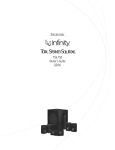
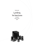
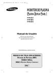
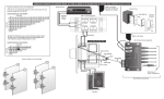
1
A / V
D I S T R I B U T I O N
&
C O N T R O L
S Y S T E M S
CA4.4pi
Instruction Manual
4-Zone, 4-Source
Central Controller/Amplifier
TUNER
CD
TAPE
S
O
U
R
C
E
AUX
• ON / OFF
• VOLUME
• SOURCE
SOURCE
REMOTE SENSOR
4
Z
O N E
—
4
S
O U R C E
C
E N T R A L
C
O N T R O L L E R
/ A
M P L I F I E R
ON
1
OFF
POWER
2
3
4
ZONE
CA 4.4pi
1. Safety Instructions
“WARNING” “ TO REDUCE THE RISK OF FIRE OR
ELECTRIC SHOCK, DO NOT EXPOSE THIS APPLIANCE TO RAIN OR MOISTURE.”
“CAUTION” “ TO REDUCE THE RISK OF ELECTRIC
SHOCK, DO NOT REMOVE COVER. NO USER SERVICEABLE PARTS INSIDE. REFER SERVICING TO
QUALIFIED SERVICE PERSONNEL.
The lightning flash with arrowhead symbol, within an equilateral triangle, is intended to alert the user to the presence
of uninsulated “dangerous voltage” within the products
enclosure that may be of sufficient magnitude to constitute
a risk of electric shock to persons.
The exclamation point within an equilateral triangle is
intended to alert the user to the presence of important
operating and maintenance (servicing) instructions in the literature accompanying the appliance.
Safety Instructions
1. Read Instructions - All the safety and operating instructions should
be read before the appliance is operated.
2. Retain Instructions - The safety and operating instructions should be
retained for future reference.
3. Heed Warnings - All warnings on the appliance in the operating
instructions should be adhered to .
4. Follow Instructions - All operating and user instructions should be
followed.
5. Water and Moisture - The appliance should not be used near water for example, near a bathtub, washbowl, kitchen sink, laundry tub, in
a wet basement, or near a swimming pool, and the like.
6. Carts and Stands - The appliance should be used only with a cart or
stand that is recommended by the manufacturer.
An appliance and cart combination should be
moved with care. Quick stops, excessive force
and uneven surfaces may cause the appliance
and cart combination to overturn.
7. Wall or ceiling Mounting - The appliance should
be mounted to a wall or ceiling only as recommended by the manufacturer.
8. Ventilation - The appliance should be situated so that its location or
position does not interfere with its proper ventilation. For example,
the appliance should not be situated on a bed, sofa, rug, or similar
surface that may block the ventilation openings or, placed in a built in installation, such as a bookcase or cabinet that may impede the
flow of air through the ventilation openings. Place the CA4.4pi in a
well-ventilated location, leaving at least 2 inches (5cm) of clearance
on all sides, top and rear of unit for air flow. If ventilation is blocked,
the CA4.4pi may overheat and malfunction.
9. Heat - The appliance should be situated away from heat sources
such as radiators, heat registers, stoves, or other appliances ( including amplifiers ) that produce heat.
10. Power Sources - The appliance should be connected to a power
supply only of the type described in the operating instructions or as
marked on the appliance.
11. Grounding or Polarization - The precautions that should be taken so
that the grounding or polarization means of an appliance is not
defeated .
12. Power - Cord Protection - Power supply cords should be routed so
that they are not likely to be walked on or pinched by items placed
upon or against them, paying particular attention to cords at plugs,
receptacles, and the point where they exit from the appliance.
13. Cleaning - The appliance should be cleaned only as recommended
by the manufacturer.
2
14. Non-use Periods - The power cord of the appliance should be
unplugged from the outlet when left unused for a long period of time.
15. Object and Liquid Entry - Care should be taken so that objects do
not fall and liquids are not spilled into the enclosure through the
openings.
16. Damage Requiring Service - The appliance should be serviced by
qualified service personnel when:
A. The power - supply cord or the plug has been damaged; or
B. Objects have fallen, or liquid has been spilled into the appliance; or
C. The appliance has been exposed to rain; or
D. The appliance does not appear to operate normally; or
E. The appliance has been dropped or the enclosure is damaged.
17. Servicing - The user should not attempt to service the appliance
beyond that described in the operating instructions. All other servicing should be referred to qualified service personnel.
Precautions
1. Power – WARNING - BEFORE TURNING ON THE POWER FOR
THE FIRST TIME , READ THE FOLLOWING SECTION CAREFULLY.
All CA4.4pi models are designed for use with either 110 VAC 50-60
Hz. or 240 VAC 50-60 Hz. A voltage selection switch is located on
the rear of the CA4.4pi above the power receptacle. The voltage
selection switch will come set to the 110 VAC position. If you are in
an area which has a 220 VAC or 240 VAC supply, move the voltage
selection switch to the 240 VAC position.
2. Do Not Touch The CA4.4pi With Wet Hands. Do not handle the
CA4.4pi or power cord when your hands are wet or damp. If water or
any other liquid enters the CA4.4pi cabinet, take the CA4.4pi to qualified service personal for inspection.
3. Location of the CA4.4pi - Do not expose the CA4.4pi to direct sun
light or heating units as the CA4.4pi internal components temperature
may rise and shorten the life of the components. Avoid damp and
dusty places .
4. Care – From time to time you should wipe off the front and side panels and the cabinet with a soft cloth. Do not use rough material,
thinners, alcohol or other chemical solvents or cloths since this may
damage the finish or remove the panel lettering.
Contents
1. Safety Instructions . . . . . . . . . . . . . . . . . . . . . . . . . . . . . 2
2. Introduction . . . . . . . . . . . . . . . . . . . . . . . . . . . . . . . . . . 3
3. Possible System Configurations. . . . . . . . . . . . . . . . . . . . 3
4. Unpacking and Warranty Card. . . . . . . . . . . . . . . . . . . . 3
5. Getting Started . . . . . . . . . . . . . . . . . . . . . . . . . . . . . . . . 3
6. Basic Planning and Layout Considerations . . . . . . . . . . . 4
7. Back Panel Connections . . . . . . . . . . . . . . . . . . . . . . . . . 4
7.1 Source Input Connections . . . . . . . . . . . . . . . . . . . . 4
7.2 Speaker Connections. . . . . . . . . . . . . . . . . . . . . . . . 4
7.3 Zone Pre-Amp Outputs . . . . . . . . . . . . . . . . . . . . . . 5
7.4 12-Volt Trigger Output. . . . . . . . . . . . . . . . . . . . . . . 5
7.5 Mute Input. . . . . . . . . . . . . . . . . . . . . . . . . . . . . . . . 5
7.6 Connecting The Infra-red Components . . . . . . . . 5-6
7.7 Connecting the IR Link . . . . . . . . . . . . . . . . . . . . . . 6
7.8 Keypad Connections . . . . . . . . . . . . . . . . . . . . . . . . 6
8. Keypad Installation . . . . . . . . . . . . . . . . . . . . . . . . . . . . . 6
8.1 Installing the KP Keypads. . . . . . . . . . . . . . . . . . . . . 6
8.2 Installing the LRN Keypads . . . . . . . . . . . . . . . . . . . 7
9. Speaker Installation. . . . . . . . . . . . . . . . . . . . . . . . . . . . . 7
10. Operation . . . . . . . . . . . . . . . . . . . . . . . . . . . . . . . . . . . 7
11. Technical Information: . . . . . . . . . . . . . . . . . . . . . . . . . 8
12. Warranty. . . . . . . . . . . . . . . . . . . . . . . . . . . . . . . . . . . . 8
2. Introduction
Congratulations on your recent purchase of the Russound CA4.4pi multi-room controller. This four-zone, foursource, multi-room controller is an affordable integrated amplifier. The CA4.4pi controller is the heart of the system. Four high current stereo power amplifiers are built into the Russound CA4.4pi allowing simple connections
to each speaker in the system. Each zone is operated by an intuitive easy-to-use keypad. The keypad controls all
the functions of the CA4.4pi controller. CA4.4KP keypads have a built-in infra-red receiver used to repeat your
source equipment remote functions back through the CA4.4pi controller.
The Russound CA4.4pi is built with pride. Fidelity, Reliability and Quality is the primary objective. Russound
products are guaranteed to provide years of enjoyment. The CA4.4pi is UL listed and CSA approved for your protection and peace of mind. Please take a moment to fill out the warranty card and return it to Russound.
3. Possible System Configurations
ZONE 3
Library
ZONE 4
Guest Room
CASSETTE
CD
SOURCE ROOM
Family Room
ZONE 1
Living Room
ZONE 2
Kitchen
TUNER
CD
CASSETTE
DSS
TUNER
CA4.4pi
Controller
DSS
(Audio Signal)
4. Unpacking and Warranty Card
• Carefully unpack the CA4.4pi and keep the original carton and
packing materials for future moving, shipment or long-term storage. After opening the box, please check for any visible signs of
damage that were not apparent from the outside of the box. If you
do encounter what appears to be concealed damage, please consult your Russound dealer before proceeding to further unpack or
install the unit.
• Make sure to save your sales receipt. Your receipt is extremely
important to establish the duration of your limited Warranty, and
for insurance purposes.
• Warranty Card – The serial number appears on the rear panel of
this unit near the power cord. Copy the serial number onto your
warranty card and mail it back to Russound / FMP, Inc. 5 Forbes
Road, Newmarket, New Hampshire, 03857, USA. Be sure to
retain a copy and keep it in a safe place.
5. Getting Started
The following information will indicate some tools and materials necessary for a complete installation of the
CA4.4pi:
• 4 twisted pair communication wire (commonly referred to as CAT 5). This wire will be used to connect the
keypads in each zone to the CA4.4pi controller. 16 Gauge minimum, 2 conductor CL3 rated wire. (Russound
AW162CL3) This wire is used for direct connection between the CA4.4pi and your speakers.
• A small jewelers flat-head screwdriver.
NOTE: CAT5 should not be run more than 100’ or
• A medium sized flat-head screwdriver.
in combination with the CA4.4 LRN. For runs
more than 100’ or when using optional CA4.4 LRN
• Wire strippers and cutters.
please use 8-conductor 20AWG wire shielded.
• Electric drill and a 1/2" x 6 "drill bit.
• A steel-wire fish tape.
Speaker Wire Length
Gauge of Speaker Wire
Additional tools required to complete installation:
10-50 feet . . . . . . . . . . . . . . . . . . . . . . .18 AWG
• A keyhole saw.
50-100 feet . . . . . . . . . . . . . . . . . . . . . .16 AWG
• Electrical junction boxes (6).
100-150 feet . . . . . . . . . . . . . . . . . . . . .14 AWG
• A stud finder.
Over 150 feet . . . . . . . . . . . . . . . . . . . .12 AWG
• A screwdriver (cordless recommended)
• Misc. hand tools, nails & screws.
• Cable staples.
If you have problems or you are not absolutely comfortable with what you are doing, consult a professional
carpenter, electrician, or system installer.
3
6. Basic Planning and Layout Considerations
• Where will the speakers be located ?
• How will the wiring be routed to each
location ?
• Where will the keypads be located ?
• Where is the equipment located ?
• Where is the CA4.4pi controller going
to be located ?
Connection Tips
• Disconnect all power cords before connecting to the CA4.4pi.
• Verify that all connections and polarity are correct.
• Keep all power cords away from all signal cables to prevent
noise or humming.
• Choose reliable signal cables / patch cords.
• Label all wires with room location at both ends of the wire.
• Take your time!!! Don't panic about the number of wires;
simply connect one at a time.
7. Back Panel Connections
7.1 Source Input Connections
• Your source inputs are located at the top left corner of the back panel. Connect each source output, left and
right, using quality signal cables / patch cables. Label each cable the name of your source and the input number of the CA4.4pi you have selected. Repeat until all sources are connected. List them down below.
figure 1: Input 1 ______________ Input 2 ______________ Input 3 ______________ Input 4 ______________
7.2 Speaker Connections
• Keeping in mind the location of the corresponding keypad, connect your speakers by first removing the connector. Using wire strippers, strip back 1/8" of the end of the wire. Insert the proper polarity, left + to left +, leftto left- etc., until all wires are connected in each zone output. Label each wire with the room name and zone
number. Write down the room name to the zone number below. Note: We recommend 8 Ohm minimum
speakers for each zone. However, as low 4 Ohm speakers can be safely used in up to two zones if necessary.
figure 2:
(Color) Left + _______________ Left - _______________ Right + _______________ Right - _______________
Zone 1 ________________________________________ Zone 2 ________________________________________
Zone 3 ________________________________________ Zone 4 ________________________________________
TUNER
CD
TAPE
AUX
• ON / OFF
• VOLUME
• SOURCE
Source Inputs
CD
TAPE
Keypad Zone
Connectors
SOURCE
REMOTE SENSOR
CA4.4pi NEWMARKET, NH U.S.A.
TUNER
S
O
U
R
C
E
AUX
INPUT FROM KEYPADS
4
3
2
1
1 2 3 4 5 6 7 8
1 2 3 4 5 6 7 8
1 2 3 4 5 6 7 8
1 2 3 4 5 6 7 8
ZONE PREA
R
L
12V
TRIG
OUTPUT TO 8Ω SPEAKERS
IR
LINK
4
IR REMOTE OUTPUT
4
3
2
3
2
4
Emitter Outputs
4
TELEPHONE
1
USE #1 FIRST
12V IR
Trigger Link
1
Speaker Output
Connectors
3
M
IN
7.3 Zone Pre-Amp Outputs
In applications where more power than the 20 watts
per channel is desired, connect the CA4.4pi to an
external amplifier. Using standard RCA connectors,
wire from the pre-amp outputs of the CA4.4pi to the
amplifier's inputs. A typical application for more power is when connecting an outside zone where the audio
power requirements would be much greater than an inside zone.
ZONE PREAMP OUTPUTS
POWER
R
L
4
3
2
1
7.4 12-Volt Trigger Output
The 12 volt trigger is engaged when any of the zones are on. The
trigger can be used to engage any 12 volt triggered accessory, such
as a triggered AC outlet or audio amplifier. The connection for the
trigger is made by an 1/8” phono jack. The tip is (+) and sleeve is (-).
12V
TRIG
POWER
7.5 Mute Input
When used with the optional Doorbell or Telephone interface, the Mute Input mutes the audio to the speakers
for six seconds when either the doorbell is used or when the telephone rings. The connection for the Mute Input
is made by a 1/8” male jack. The tip is (+) and the sleeve is (-).
DIM-1 Doorbell Interface
TRANS
AC
Power
TIM-1 Telephone Interface
TELEPHONE INTERFACE
POWER
PHONE LINE
+12V DC
TRIG OUT
TRIG
DB1
+12V DC
DB2
DOORBELL INTERFACE
DB3
POWER
TRIG OUT
AC
Power
TRIG
To Trigger Input on CA4.4pi
To Doorbell
To Trigger Input on CA4.4pi
To Phone Line
7.6 Connecting The Infra-red Components
• In order for your CA4.4pi to transmit the IR signal from the keypads to a source, an emitter must be connected from
the IR outputs marked 1-4. Each of these outputs are wired in series and must be connected in consecutive order. For
example, the #1 emitter output must be connected in order for the # 2 emitter output to transmit the IR command.
Voltage Selector
Switch
Zone Pre-Amp
Outputs
ADS
2
ZONE PREAMP OUTPUTS
1
~220-240VAC
~110VAC
R
3 4 5 6 7 8
1 2 3 4 5 6 7 8
L
AKERS
2
1
4
3
2
TELEPHONE
MUTE
INPUT
Mute Inputs
1
DOOR
BELL
WARNING : SHOCK HAZARD –
DO NOT OPEN
AVIS : RISQUE DE CHOC
ELECTRIQUE – NES PAS OUVRIR.
SERIAL #
~110VAC
~220-240VAC
~50-60Hz
400W
AC110/240
Input
VOLTAGE FUSE
110V
F4A
220-240V F2A
Fuse
Holder
5
CD PLAYER
• Connect each 845 mini-emitter to the source IR output. Refer to the source
number you had written down in figure 1.
• Remove the adhesive back and locate the IR receiver on the product you wish to
control. Stick the 845 emitter directly over the source components IR
REAR OF
window. The CA4.4pi will direct the IR command to the source
CA4.4pi
component you wish to control.
845
EMITTER
CASSETTE DECK
845
EMITTER
TUNER
• Repeat connections until all emitters match the selected sources.
845
EMITTER
TO OTHER SOURCE
845
EMITTER
7.7 Connecting the IR Link
• When two CA4.4pi Controllers are to be used in an installation, the IR Link connection is used to pass IR signal between the two units. Use a 1/8”, mono, phone plug, male to male cable connected from the IR Link on
the first CA4.4pi Controller to the IR Link on the second CA4.4pi. When connected, you may connect your IR
emitters to either unit’s IR Remote Output jacks.
7.8 Keypad Connections
• Each keypad connection on the back panel corresponds to the room / zone number chosen for your speakers.
Each zone operates independently, so it is very important to connect the keypad to the correct zone keypad
input. Remove the connector and strip 1/8" off each end of the wire insulation. Connect each wire 1 thru 8
using a small jewelers screwdriver. At this point it is not important what color wires connect where, however,
take note of the color of each wire and number indicated on the connector when connected to the back panel.
• Write down the room name to the zone number below. Note: the keypad and the speakers in each room
must be hooked to the same zone number. See figures 2 and 3
figure 3
Zone 1 _______________ Zone 2 ______________ Zone 3 _______________ Zone 4 ______________
8 7 6 5 4 3 2 1
figure 4 –Connector numbers and wire color should be written down below.
Pin 1 ________ Pin 2 ________ Pin 3 _________ Pin 4 _________
Pin 5 ________ Pin 6 ________ Pin 7 _________ Pin 8 _________
8. Keypad Installation
8.1 Installing the KP Keypads
• The best performance is achieved with the keypad away from any direct sunlight.
Also consider the convenience when choosing a location.
• Choose a place that is easily seen from the position where a person is most likely to be located.
• Check whether or not you can route the wire to the location you have chosen.
• Purchase retro-fit plastic junction boxes (min. 20 cubic inches) and cut in the boxes using a key-hole saw or
sheetrock knife/hand saw.
• Route the wire to the junction box from the CA4.4pi location.
• Strip the insulation back 1/8" from each twisted wire. Connect each wire to the correct position 1 thru 8. Refer
to figure 4.
• If you feel uncomfortable cutting into your walls and running wire through the walls, seek help from a professional installer or an electrician.
• Mount the keypad in the junction box and attach the Decora plate.
• The CA4.4 KP keypad has source labels for your convenience. Place the label on the keypad keeping the
input number in sequence with the source selected.
• Repeat the above steps until all keypads are installed.
6
8.2 Installing the LRN Keypads
• Connect the CA4.4 LRN’s Interface cable to the 16 pin header
located on the CA4.4 KP. Note the location of the red stripe.
• Mount the keypads into double gang box and
attach the double gang Decora plate.
INTERCONNECT
CABLE
RED
STRIPE
9. Speaker Installation
• If you are installing in-wall speakers, follow the instructions
provided with your speakers for mounting.
• Connect each speaker wire to the correct polarity (+,-).
Finally!!!
• Make sure that the voltage selector is on the correct
current for your country, either 110V or 220V
• Power up by plugging in all power cords and turning
the CA4.4pi and sources on.
8 7 6 5 4 3 2 1
CA4.4 LRN
CA4.4 KP
RED
STRIPE
-
+
10. Operation
• Power switch - When the power switch is engaged, the CA4.4pi power indicator will be lit an amber color.
The CA4.4pi should be left on at all times. The unit will consume very little power unless the zones are on and
active. The unit has a stand-by mode when the zones are inactive.
• The zone indicator will light either red for off or green for on. The zones can only be turned on from the keypads. All functions are accessed through the keypad only.
•
•
•
•
Operating The CA4.4 KP Keypad
Power ON / OFF - This knob on the CA4.4 KP keypad controls all functions
except for the IR management. To turn the unit on, simply turn the control knob
clock-wise. You will feel and hear a click verifying that the unit has been activated. The lights on the keypad will also illuminate to verify the zone is now
on. Note - The CA4.4pi front panel zone-management lights also informs you
which zone is On or Off.
Volume UP / DOWN - Once the unit is on, the knob can be used to adjust the
volume. To adjust the volume up, turn the knob clockwise, and to turn the volume down, turn counter-clockwise.
Source Selection - By pressing the knob, the zone will scroll through the four
sources connected to the CA4.4pi. The keypad has four lights (LED's) that indicate the source selected.
IR Source Control - The IR window repeats all source commands from the
source component's remote through the CA4.4pi and 845 emitters. Most IR
receivers have a range of 20' at an angle of 60-65 degrees.
TUNER
CD
TAPE
S
O
U
R
C
E
AUX
• ON / OFF
• VOLUME
• SOURCE
SOURCE
REMOTE SENSOR
7
11. Technical Information:
• Frequency Response: 20 Hz to 20 KHz ( +/- 1 dB )
• 15 Watts RMS / Channel @ 8Ω
• 8 Channels / 4 Stereo Amplifiers
• Total Harmonic Distortion: .1%
• Signal to Noise Ratio: 89 dB min, “A” weighted
• Power Supply: ~110VAC/~220-240VAC 50-60Hz
400W High Current Toroidal
• ETL listed. Conforms to UL Standard UL1492
and CSA Standard C22-2 No. 1-M94
• CE Approved
• Fully Functional Keypad with IR Receiver
Centered at 40 KHz
12. Warranty
The Russound CA4.4pi is fully guaranteed for Two (2) years from the date of purchase against all defects in materials and workmanship. During this period Russound will replace any defective parts and correct any defect in
workmanship without charge for either parts or labor. For this warranty to apply, the unit must be installed and
used according to its written instructions. If service is necessary, it must be performed by Russound. The unit must
be returned to Russound at the owners expense and with prior written permission. Accidental damage and shipping damage are not considered defects under the terms of the warranty. Russound assumes no responsibility for
defects resulting from abuse or servicing performed by an agency or person not specifically authorized in writing
by Russound. Damage to or destruction of components due to improper use voids the warranty. In these cases
the repair will be made at the owners expense. To return for repairs, the unit must be shipped to Russound at the
owners expense, along with a note explaining the nature of the service required. Be sure to pack in a corrugated
container with at least 3 inches of resilient material to protect the unit from damage in transit.
Now sit back and let all members of the household enjoy the personalization
that the Russound CA4.4pi provides. Happy listening!
A / V
D I S T R I B U T I O N
&
C O N T R O L
S Y S T E M S
5 Forbes Rd. Newmarket, NH 03857, USA
☎ 603.659.5170 • Fax 603.659.5388
e-mail: [email protected]
Come visit us at:
8