1
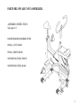
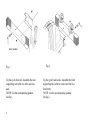
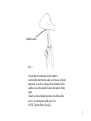
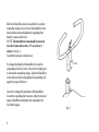
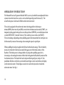
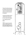
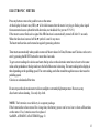
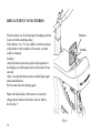
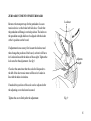
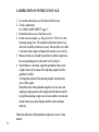
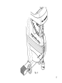
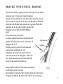
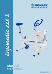
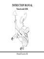
INSTRUCTION MANUAL Monark model 828E Monark Exercise AB CONTENTS Assembly instructions Brake surface - brake belt Calibration Chain Crank bearing Elektronic meter Flywheel bearing General General about exercise Freewheel lubrication Operation instruction Replacement - adjustment brake belt Replacement of batteries Replacement of freewheel sprocket Service checklist Warrenty Zero adjustment scale Page 6-9 19 16-17 20-21 24 12-14 24 4 25-27 22-23 10-11 18 14 22-23 24 4 15 3 CONGRATULATIONS ON YOUR NEW EXERCISE BIKE designed by Monark Exercise AB, Sweden. Monark has been the worlds leading manufacturer of high quality ergometers and exercise cycles for more than 40 years. GENERAL It is important that you keep your ergometer clean and properly lubricated. Most important is to protect the chromed and zinced parts but also painted parts benefit from the same protection. When cleaning and lubricating be sure to check that all screws and nuts are properly tightened. Be sure that all moving parts as crank and flywheel is working normal and that no unnormal play or sound excists. I. e. play in bearings causes fast waring and with that follows a highly reduced lifetime. PLEASE NOTE: The production number of your exercise cycle is placed according to fig 1 page 6. WARRANTY As on any quality product there may be an exceptional fault due to material or manufacture. If such a fault should arise on your exercise cycle, please return to the place of purchase for necessary repair. Monark products and parts are guaranteed against defects in materials and workmanship for a period of one year from the initial date of purchase of the unit. Parts found to need replacement due to normal wear and tear, such as brake belts, are not covered. This guarantee covers parts only, not labor costs associated with the repair. This guarantee does not apply to cases of abuse or vandalism, nor does it extend to any injury or loss to person or property caused directly or indirectly by any Monark products. In the event of a defect in material or workmanship during the warranty period, Monark Exercise will repair or replace (at its option) the product. Monark Exercise will do so at its expense for the cost of materials but not for labour or shipping 4 PARTS BELOW ARE NOT ASSEMBLED. ASSEMBLY INSTRUCTION: See pages 6-9. HANDLEBAR/HANDLEBAR STEM PEDAL, LEFT HAND PEDAL, RIGHT HAND SUPPORTING TUBE, FRONT SUPPORTING TUBE, REAR 5 Serial number Fig. 1 Tip the cycle forward. Assemble the rear supporting tube with two bolts and two nuts. NOTE: Use the accompanying spanner. See fig 1. 6 Fig. 2 Tip the cycle backwards. Assemble the front supporting tube with two nuts onto the two fixed bolts. NOTE: Use the accompanying spanner. See fig 2. Saddle bracket Fig. 3 Check that the inclination of the saddle is comfortable and that the sadle post bracket is firmly tightened. In order to change the inclination of the saddle, loosen the saddle bracket and tighten firmly again. Adjust to desired height position of saddle/saddle post by loosening the saddle post bolt. NOTE: Tighten firmly. See fig 3. 7 Before the handlebar stem is assembled be sure the expanding wedge is loose. Insert the handlebar stem into the frame tube and tighten the expanding bolt firmly by means of the lever. NOTE: The handlebar stem should be inserted into the frame tube at least 7.5 cm (about 3 inches). See fig. 4. Usually this measure is marked out. 7.5 cm To change the height of the handlebar, loosen the expanding bolt about 5 mm. Give the bolt a light push to release the expanding wedge. Adjust the handlebar to the desired position and tighten the expanding bolt again by means of the lever. In order to change the inclination of the handlebar, loosen the expanding bolt one turn. Adjust to desired angle of handlebar and tighten the expanding bolt/ lever firmly again. 8 Fig 4 Pedal marked R (Right) is to be assembled on the right hand side of the cycle (the chain wheel side). The pedal axle has a right hand thread and must be threaded onto the crank clockwise. Tighten firmly. See fig 6. L left Pedal marked L (Left) is to be assembled on the left hand side of the cycle. The pedal axle has a left hand thread and must be threaded onto the crank counter clockwise. Tighten firmly. See fig 5. NOTE! Check now and then that both pedals are still firmly tightened. If not the threading in the pedal arms will be damaged. Also check that the pedal arms are firmly tightened on the crank axle. If nessecary tighten. Fig. 5 R right 9 OPERATION INSTRUCTION The Monark Exercise Ergometer Model 828E is a test cycle which has an adjustable brake system where the brake force can be set/read in kilopond (kp) and Newton (N). The actual brake power is showed in Watts on the electronic meter. The cycle is equipped with an electronic meter showing pedal revulotions per minute (RPM), heart rate in bpm (HR), exercise time in minutes and seconds (TIME), an imagined cycling speed in km per hour or miles per hour (SPEED), covered distance in km or mile (DISTANCE), burned Calories (CAL) and the power on the cycle(WATT). The watt reading is depending on the pedalling speed which means that the watt figure can be fine tuned by means of increasing or decreasing the speed or pedal rpm. When pedalling the subject supplies the flywheel with a kinetic energy. This is braked by means of a brake belt which runs around the bigger part of the brake surface of the flywheel. The brake power is changed either by using other pedalling speed or by increasing or decreasing the tension of the brake belt against the flywheel by means of the load tension device. The harder the load is adjusted the larger figure, in kp or N, the pendelum will show on the force scale and the watt figure can be read in the watt display on the electronic meter. The kp figure can also be read in the kp window beside the electronic meter. See fig. 6. 10 The height of the saddle should be adjusted so that, when sitting comfortably with the middle of the foot above the pedal axle and with the pedal in its lowest position, the knee should only be slightly bent. The adjustment of the handlebar should give a comfortable ride. When cycling for a long time, it may be suitable some time during the exercise to change the position of the handlebar. NOTE! At transport the tension device should be somewhat tightened to prevent the brake belt from falling off the fltwheel. Fig. 6 11 ELECTRONIC METER SPECIFICATIONS: RPM: HR: TIME: SPEED: DISTANCE: FORCE CALORIES WATT 0 - 199 50 - 240 0:00 - 99.59 0 - 99 0.0 - 99.9 0.0 - 7.0 0 - 999 0 - 7 x rpm Batteries: Storing temp.: Operating temp.: Fig. 7 12 pedalrev./min bpm min:sek km/h or mph km or mile kp kcal watt 1.5 V x 2 AA(R6) -10ºC - +60ºC 0ºC - 50ºC ELECTRONIC METER Press any button or move the pedal to turn on the meter. At the display for heart rate (HR) a © is lit which means that the meter is trying to find a pulse signal from an external source (chestbelt with electrodes, not included. Our part.no 9339-91). If the meter can not find such a signal this HR function is automatically turned off after 30 seconds. When the function is turned off the © symbol is not lit any more. The heart rate function can be turned on again by preessing a button. Timer starts automatically when pedals are moved. Meter values for Time, Distance and Calories can be set to zero by pressing the RESET button for more than 2 seconds. To get correct raedings for calories and watts the kp value on the electronic meter has to be set to the same value as the pendelum or the kp window to the left of the meter is showing. The watt reading in the display is then depending on the pedalling speed. The watt reading can be fine tuned through increase or decrease the pedalling speed. Calories are calculated all the time. Do not expose the electronic meter to direct sunlight or extremely high temperature. Do not use any dissolvents when cleaning. Use only dry cloth. NOTE: The batteries are at delivery in a separat package. If the batteries have been stored for a long time, the battery power can be too low to show all functions on the meter. If so, batteries must be replaced. See REPLACEMENT of BATTERIES page 13. 13 REPLACEMENT OF BATTERIES Take the meter out of the housing by bending up in the lower end with something sharp. The batteries, 2 x 1.5V size AA(R6), which are placed in the holder on the backside of the meter, can then easily be changed. See fig.8. After the batteries has been replaced all segments in the display are visible and a buzzer will sound for two seconds. After 2 seconds the meter turns to main display again and normal function. Put the meter into the housing again. Batteries km/mile Note: On the backside of the meter is a switch to change meter function from km to mile or mile to km.See fig. 9. 14 Fig. 8 ZERO ADJUSTMENT OF METER BOARD Remove the transport tape for the pendulum. Loosen tension device so the brake belt feels loos. Check that the pendulum will hang in vertical position. The index on the pendelum weigh shall now be aligned with the index at the 0-position on the board. Lock nut If adjustment is necessary, first loosen the lock nut and then change the position of the board, so that it will have its 0-index in line with the index of the weight. Tighten the lock nut after the adjustment. See fig 9. Adjustm. weight Check at the same time that the scale for kiloponds to the left of the electronoic meter will have its 0-index in line with the index in window. If needed the position of the scale can be adjusted after the adjusting screw has been loosened. Tighten the screw firmly after the adjustment. Fig. 9 15 CALIBRATION OF PENDULUM SCALE 1. Loosen the tension device so the brake belt feels loose. 2. Check 0-adjustment. See ZERO ADJUSTMENT page 15. 3. Detatch the front screw in the frame covers. 4. Fasten a known weight, e.g. 4 kg (our ref No. 9000-211) at the balancing spring. Note: The weight should not be less than 3 kg, due to the possibility of inferior accuracy. Take the left cover a little to the side so the weight cord hangs between the covers. See fig. 5. When correctly set, it should be possible to read this weight from the corresponding place on the meter board. See fig 10. 6. Should there be a deviation, adjust the pendulum to the correct weight on the scale by means of the adjusting weight inside the pendelum. See fig 9. To change the position of the adjusting weight, loosen the lock screw of the weight. Should the index of the pendulum weight be too low, move the adjusting weight upwards in the weight and if the index should be too high the adjusting weight is moved somewhat downwards and locked in the new position. Repeat until the correct reading is achieved. 16 Check the calibration of the pendulum weight once a year or when needed. Fig. 10 17 REPLACEMENT OF BRAKE BELT Remove the tension lever. Dismantle the front cover over the pendelum weigh by detatching the 4 screws underneath. Remove the left or the right frame cover by undoing the mounting screws (5pcs). Put the crank in a backward position. Move the cover somewhat out in the front end and then take it backwards to remove it. Loosen the brake belt from the pendelum at the screw and lock washer. Take it apart at the spring and clip and remove it from the bike. See fig 11. Attach the new brake belt and assamble the bike in reverse order. NOTE: When replaceing the brake belt it is recommended to clean the brake surface. See Brake Belt Contact Surface. Tension lever Lock washer ADJUSTMENT BRAKE BELT Loosen the tension device to min. load. Adjust the brake belt so that resistance increases as soon as a the tension device is turned a little. See fig. 10. 18 Fig. 11 Clip BRAKE BELT CONTACT SURFACE - BRAKE BELT The brake belt should be regularly checked to ensure that it has not suffered execessive wear. If it looks worn it should be replaced. Deposits of dirt on the brake belt and on the contact surface may cause the unit to operate unevenly and will also wear down the brake belt. The brake belt contact of the flywheel surface should then be ground off with a fine sand paper and any dust removed with a clean dry cloth. Dismantle cover see REPLACEMENT BRAKE BELT. Set the tension device to min load. Loosen the brake belt somewhat at the adjustment bolt Brake surface and take off the brake belt to the side. Grind with a fine sand paper. See fig. 12. Sand paper Grinding is easier to perform if a second individual cautiously and carefull pedals the cycle. Irregularities on the brake belt contact surface are removed by means of a fine sand paper or an abrasive cloth. Otherwise unnecessary wear on the brake belt may occur and the unit can become noisy. Always keep the brake belt contact surface clean and dry. No lubricant is allowed to be used. We recommend to replace the brake belt when cleaning the contact surface. As regards assembly and adjustment of the brake belt, see previous page. Fig.12 19 CHAIN ½ x 1/8 It is strongly recommended that a cahin solvent be used to keep the chain clean. Excess dirt built up on the chain will cause excess wear. A chain lubricant and solvent for normal road bikes may be uaed. Check the lubrication and tension of the chain at regular intervals. In the middle of its free length the chain should have a minimum play of 5 mm. See fig 12. When the play in the chain is about 20 mm (<1 inch) the chain must be tightened otherwise it will cause unnormal wear of the chin and chainwheels. Because of this it is always recommende to keep the chain play as little as possible. When the chain has become so long that it can no longer be tightened with the chain adjusters it is worn out and shall be replaced with a new one. ADJUSTING CHAIN Remove left and right frame cover. See RRPLACEMENT of BRAKE BELT. To adjust the chain the hub nuts should be loosened. Loosening or tightening the nuts on the chain adjusters will then move the hub and axle forward or backward. Adjust according to above recommendation. Then tighten the nuts on the hub axle again. See fig 12. CHAIN REPLACEMENT Loosen the chain adjusteras much as possible. Dismantle the cahinlock and remove the chain. Put on a new chain and assemble the chain lock.The spring of the chain lock should be assembled with the closed end in the movement direction of the chain. Use a pair of tongs for dismantling and assembling the spring. See fig 13. Adjust chain adjusters to chainplay according to above. Tighten axle nuts firmly. Put on frame covers again. NOTE: At assembly the flywheel has to be parallell with the center line of the frame. Otherwise the chain and chainwheels makes a lot of noise and wears out very rapidly. 20 Kedjesträckare Axelmutter Kedjespel Fig. 13 Låsfjäder Kedjelås Fig. 14 21 REPLACEMENT OF THE FREEWHEELING SPROCKET Remove left and right frame cover. See REPLACEMENT OF BRAKE BELT. Dismantle the chain as described on page 20 - 21. Loosen the axle nuts and lift off the flywheel. Remove the axle nut, washer, chain adjuster and spacer on the freewheel side. Place the special remover (part No. 9100-14) in the adapter and place the spacer and axle nut outside. See fig 15. NOTE: Do not tighten the axle nut completely. It must be possible to loosen the adapter-sprocket half a turn. Replace sprocket-adapter and assemble the new parts in reverse order according to the above. LUBRICATION SPROCKET The sprocket should be lubricated with a few drops of oil once a year. Incline the cycle somewhat to make it easier for the oil to reach the bearing. See fig 16. 22 Fig. 15 Fig. 16 23 CRANK BEARING The crank bearing is long term greased and needs normally no supplementary lubrication. If problem arises, please contact your Monark dealer. FLYWHEEL BEARING The bearings in the flywheel are lifetime greased and require normally no maintenance. If problem arises, please contact your Monark dealer. SERVICE CHECKLIST Check the: ¨ chain is snug and there is no play on the pedal crank ¨ pedal crank is secure to the crank axle ¨ pedals moving smoothly, and is the pedal axle clear of dirt and fibres ¨ pedals are securely fitted to the pedal crank ¨ handlebar not higher than min required insertion length ¨ flywheel rotating smoothly and central ¨ handlebars and saddle adjustment screws lubricated ¨ pressure washer on saddle tube is present ¨ saddle clip is tight and that the saddle is at a correct angle. ¨ brake belt does not show significant signs of wear ¨ pedals and chain are lubricated 24 THE IMPORTANCE OF REGULAR EXERCISE The human body is built for action not for rest. Once upon a time this was a necessity: the struggle for survival demanded good physical condition. But optimal function can only be achieved by regularly exposing the heart, circulation, muscles, tendons, skeleton and nervous system to some loading, i.e. training. In the old days the body got its exercise both in work and at leisure. In our modern society, however, machines have taken over an ever increasing share of the tasks which were formerly accomplished with muscular power alone. Our life has at an accelerated tempo been dominated by sitting, riding and lying. Thus, the natural and vital stimulation that tissues and internal organs receive through physical exercise has largely disappeared. Certain tissues such as muscles, bone and blood and also a number of bodily functions can adapt to inactivity and to stress. Studies have proved that if you use 30 minutes for exercise like brisk walking, running, bicycling, swimming or skiing 2-3 times a week, your condition has been improved by some 15 per cent after a few months. The efficiency of the heart muscle will increase and joints and muscles grow in strength. The capillary density increases in the trained muscle and their enzymatic activities are enhanced. The body adapts to the new demands. The perceived exertion at a given rate of exercise becomes reduced. With increased physical activity fatness is concentrated, the appetite functions safer, you can eat more without risk for overweight and thereby the risk of lack of important essential food nutrients decreases. For many individuals the effect of habitual physical activity also improves the wellbeing and it is a good feeling to have a potential to cope with straining situations. 25 What kind of exercise to choose? 1. You should have fun when exercising. Choose something you find pleasure in doing regularly. 2. To get o good effect out of the training you should choose a form of exercise that engages large muscle groups. Then the demand of increased blood flow and oxygen transport will be so great that heart will increase its pump capacity. Jogging, calesthenics, aerobic dancing, bicycling, swimming, skiing and walking are excellent examples of exercises meeting this requirement. IN A FEW MONTHS YOU CAN GET 10-15 YEARS YOUNGER If you cycle 30 minutes a few times a week you can lower your condition age with 10-15 years! Scientifically this is described as a reduction on the biological age. Externally, you are your usual self. Internally, however, you feel much younger. In other words: You can work harder. You feel more alert and healthy. Your ability to handle stress and problems increases. There are few better ways to improve your physical condition than to cycle. It does not over-tax your joints. It builds up your condition progressively and at your own pace and you can make your training fit weather conditions. DO I LOOSE WEIGHT WHEN I CYCLING? Yes! You do lose calories. A few miles on your bike every day over one year, you will have lost the equivalent of 20 pounds of body fat. You will achieve best results if you combine exercise with healthier eating. A little less sugar, less butter on your bread or less fat in your frying pan. And a few miles on your bike every day. In a year you will have lost 20 pounds. 26 DO I GET STRONGER? Cycling strengthens the muscles of the back, abdomen and legs. Daily chores become easier. Cycling also makes your heart stronger. Your pulse rate gets lower even when you exert yourself a little extra. Regular exercise also has a favourable influence on high blood pressures. HOW DO I TRAIN? 1. Warm up 3-5 minutes with a low pedal resistance. Pedal about 12 mph (20 km/h). 2. Increase the resistance until you feel the training somewhat hard. Keep the speed for 2-5 minutes. Get off the Ergometer and rest a few minutes. Cycle again and then rest. Train at your own pace and with a comfortable pedal resistance. After a few weeks you can increase the resistance. 3. Before ending, pedal a few minutes with a light resistance, in order to step down your training. Total time about 30 minutes. Strength training: 1. Give yourself a thorough warm-up. 2. Pedal with a heavy resistance for 5-10 seconds, then rest 45-60 seconds. Repeat this 5-10 times. It is a good idea to combine your cycle training with gymnastics for 5 minutes, as this will give you a physiologically well-balanced form of training. (Elderly people and physically weak persons should consult a doctor before starting their training.) 27 432 82 Varberg Tel: +46 0340 86000 Fax:+46 0340 80485 78050 Vansbro Tel: +46 0281 594940 Fax:+46 0281 71981