1
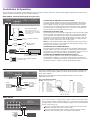
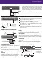
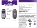
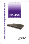
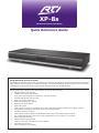
XP-8s
Advanced Control Processor
Quick Reference Guide
XP-8s Advanced Control Processor
The XP-8s is a high-end remote control processor for automating the operation of electronic systems in homes and
office buildings. The combination of a blazing fast MPU, real-time/multitasking operating system, and tremendous
expandability make the XP-8s the perfect solution for large-scale and complex projects.
The XP-8s provides superior quality and reliability as well as these features:
•
•
•
•
•
•
•
•
•
•
•
•
•
•
•
•
•
•
Powerful 532MHz i.MX processor.
128Mb of non-volatile Flash memory.
Front panel controls/display (11 Buttons for front panel control).
Includes 4GB SD Flash memory card.
Eight multi-purpose I/O ports.
Eight programmable relay outputs.
Eight two-way RS-232 ports.
Eight sense inputs.
Multi-purpose I/O ports are compatible with industry-standard IR emitters, blasters and repeater systems.
All output ports incorporate both short-circuit and overload protection.
Variable IR output on all ports.
Multi-purpose I/O ports support all optional RTI power sensing and communications modules.
Non-volatile Flash memory stores your system configuration even when power is not present.
Field upgradeable firmware.
USB and Ethernet programming.
Input for connection of multiple RF receiver modules.
Astronomical clock built in.
Rack mountable or free standing.
Touchscreen Control Panel
Installation & Operation
The XP-8s can be connected in many different ways to control a variety of devices. The following diagram illustrates just some of the
options. Optional accessories shown are sold separately.)
MPIO Ports - Infrared/Sensing/RS-232 (One-way)
CONNECTING IR EMITTERS TO OUTPUT PORTS
The multi-purpose I/O ports on the XP-8s are compatible with industry
standard infrared emitters and infrared repeating systems. Each output
port is capable of driving up to four infrared emitters directly. The use
of more than four infrared emitters requires the addition of an amplified
connecting block. A connecting block can be wired up to 1000 feet away
from the XP-8s using #22 AWG (minimum) wire.
IR Connecting Block
Each IR output can drive up to
four emitters directly. More than
four emitters require an amplified
connecting block.
ADJUSTING IR OUTPUT GAIN
The IR output gain can be separately adjusted for each of the eight output
ports. The XP-8s is shipped with the IR gain set to the optimum level for
most equipment, and it should only need to be adjusted if the attached
equipment is not responding reliably. If adjustment is needed, rotate the
IR output controls on the front of the XP-8s clockwise for higher output
power, or counter-clockwise for lower output power.
Direct to IR Port
NOTE: The IR Output Feedback LEDs will illuminate when any IR code is
delivered from the XP-8s - this includes IR codes “passing through” from
another source such as an IR receiver.
Single or Dual
IR Emitters
CONNECTING VPS-1 SENSOR MODULE
The multi-purpose I/O ports on the XP-8s are compatible with RTI power
sensing modules (e.g. VPS-1 and SPS-1). Follow the guide included with
the modules for installation instructions, and follow the instructions in the
Integration Designer® software guide for programming details.
Voltage From
Power Supply
IR Emitter
Equipment with switched outlet
or voltage trigger output
CONNECTING COMMUNICATION MODULES (CM-232)
The multi-purpose I/O ports on the XP-8s are compatible with RTI
communication modules (e.g. CM-232). Follow the guide included with
the modules for installation instructions, and follow the instructions in the
Integration Designer® software guide for programming details.
CM-232 Communication Module
(RS-232 One-way)
RS-232 Ports
The XP-8s is capable of two-way communication and uses industry standard cat5
cable with RJ-45 termination (568B). The XP-8s ships with 8 RJ-45 (female) to
DB-9 (male) adapters.
NOTE: RS-232 communication cabling should be limited to 50 feet (16m)
depending on baud rate.
DB9 - RJ45 ADAPTOR PINOUT
cat5
HVAC
RJ-45
Adapter
TV
Lighting
(XP-8s RS-232 Output)
DB-9
Pin Signal Name Signal
Description
Pin Signal Name Signal
Description 1
2
3
4
5
6
7
8
DSR
DCD DTR GND RXD TXD CTS RTS Data Set Ready
Carrier Detect
Data Terminal Ready
Signal Ground/Common
Receive Data
Transmit Data
Clear To Send
Request To Send
1
2
3
4
5
6
7
8
9
DCD RXD TXD DTR GND DSR RTS CTS NC Carrier Detect
Receive Data
Transmit Data
Data Terminal Ready
Signal Ground
Data Set Ready
Request To Send
Clear To Send
Not Connected
Sense Inputs
Sense contact closure or voltage trigger input (2-12VDC). Sense input mode
can be configured within Integration Designer®. Upon sensing contact closure
or trigger input, events can be automatically triggered such as IR commands,
macros, relay closure, etc.
Wiring for contact closure sense: connect conductors from device to be
sensed to each side of a sense input (A and B).
Wiring for voltage trigger sense: Connect positive lead from voltage
source to Side A of sense input and negative lead to Side B.
+ Security
+ Receiver
It’s Under Control®
Relay/Trigger Outputs
Configurable within Integration Designer® to be either a dry contact
closure or a voltage trigger output (12VDC @100mA). All relays are
Normally Open when not energized, but they can be programmed to
behave Normally Closed (as long as power is applied to the XP-8s).
Drapes
+ -
For contact closure control, connect the A and B contact terminals of
a relay to the desired device.
To use a relay as a voltage trigger, connect Contact A to the positive
side and connect Contact B to the ground side of the desired device.
+ -
Screen Lift
signal in/high out/power terminals
Connecting Block
To Audio/Video
Equipment, Lighting
Systems, etc.
RF or IR Receivers
TERMINAL: +12VDC
Positive power supply connection. It is internally tied to the Power jack. This
can be used to power external IR or RF receivers.
TERMINAL: GROUND
Common ground connection. Use this ground reference for any device that is
connected to the +12VDC, SIGNAL IN, OR HIGH OUT terminals.
TERMINAL: SIGNAL IN
Input connection for system trigger codes. This should be connected to an
RTI RM-433 RF receiver or industry standard IR repeater system. The signal
voltage can be from 3VDC - 12VDC.
TERMINAL: HIGH OUT
High current (200mA) IR output connection. This can be used to power up to
10 infrared mini-emitters, an IR blaster, or extending IR control over a long
distance (1000 ft. max).
Ethernet, USB, RTI COM, Expansion Port
LAN
ZM-24 Zigbee
Transceiver
(Future Use) USB
CB-8 Connecting Block
cat5
Power
Supply
ETHERNET
This RJ-45 port allows connection to a 10/100 Base-T Ethernet network (LAN).
Network settings such as the IP address are configurable within Integration
Designer®. Ethernet can be used to download system files to the XP-8s.
USB PORTS (REAR)
These are host ports for external devices and are intended for future use.
RTI COM
This RJ-45 port allows connection to a ZM-24 Zigbee® transceiver module. The
connection supports full duplex two-way communication for use with compatible
RTI handheld controllers. Refer to the ZM-24 Zigbee transceiver module
operation guide for installation instructions.
EXPANSION PORT
This RJ-45 port provides a convenient connection for receiving IR signals and
two-way RS-485 communication from RTI in-wall controls through a CB-8
connecting block.
NOTE: In-wall controllers may be connected directly to the XP-8s Expansion
Port, however, they should be powered with a separate power supply.
PROGRAMMING THE XP-8s
The XP-8s must be programmed to operate. All programming
is done using RTI’s Integration Designer® software and is
downloaded using the USB Programming Port located on front of
XP-8s or via Ethernet.
Updating firmware
It is highly recommended that this and all RTI products have
the latest firmware installed. The firmware can be found in the
Dealer section of the RTI website (www.rticorp.com). Install the
firmware using the USB Programming Port located on front of
XP-8s.
Mounting
The XP-8s ships with four removable feet that allow the
XP-8s to be placed on a flat surface. The XP-8s can also be
mounted in a component rack as part of a comprehensive
control system. Remove feet before mounting in a rack.
XP-8s Front
Menu
Display
Exit
Backlight On/Off
Reset
SD Flash Memory Slot
USB Programming Port
Rack
Mount
Option
Select
Cursor
IR Adjustment Dials
and IR Feedback LED’s
It’s Under Control®
Federal Communications Commission Notice
This equipment has been tested and found to comply with the limits for a Class B digital device, pursuant to Part 15 of the FCC Rules. These limits are designed to provide
reasonable protection against harmful interference in a residential installation. Any changes or modifications not expressly approved by the party responsible for compliance
could void the user’s authority to operate the device.
This equipment generates, uses, and can radiate radio frequency energy and, if not installed and used in accordance with the instructions, may cause harmful interference
to radio communications. However, there is no guarantee that interference will not occur in a particular installation.
If this equipment does cause harmful interference to radio or television reception, which can be determined by turning the equipment off and on, the user is encouraged to
try to correct the interference by one or more of the following measures:
Reorient or relocate the receiving antenna.
Increase the separation between the equipment and the receiver.
Connect the equipment into an outlet on a circuit different from that to which the receiver is connected.
Consult the dealer or an experienced radio/TV technician for help.
This device complies with Part 15 of the FCC Rules. Operation is subject to the following two conditions:
1. This device may not cause harmful interference.
2. This device must accept any interference received including interference that may cause undesired operation.
N27917
DECLARATION OF CONFORMITY (DOC)
The Declaration of Conformity for this product can be found on the RTI website at: www.rticorp.com/declaration
Safety Suggestions
Read and Follow Instructions. Read all safety and operating instructions before operating the unit.
Retain Instructions. Keep the safety and operating instructions for future reference.
Heed Warnings. Adhere to all warnings on the unit and in the operating instructions.
Heat. Keep the unit away from heat sources such as radiators, heat registers, stoves, etc., including amplifiers that produce heat.
Power Sources. Connect the unit only to a power supply of the type described in the operating instructions, or as marked on the unit.
Power Cord Protection. Route power supply cords so that they are not likely to be walked on or pinched by items placed on or against them, paying particular attention to the
cord plugs at power receptacles and at the point at which they exit from the unit.
Water and Moisture. Do not use the unit near water—for example, near a sink, in a wet basement, near a swimming pool, near an open window, etc.
Object and Liquid Entry. Do not allow objects to fall or liquids to be spilled into the enclosure through openings.
Servicing. Do not attempt any service beyond that described in the operating instructions. Refer all other service needs to qualified service personnel.
Damage Requiring Service. The unit should be serviced by qualified service personnel when:
The power supply cord or the plug has been damaged.
Objects have fallen or liquid has been spilled into the unit.
The unit has been exposed to rain.
The unit does not appear to operate normally or exhibits a marked change in performance.
The unit has been dropped or the enclosure has been damaged.
Limited Warranty
RTI warrants its products for a period of one (1) year; or for a period of time compliant with local laws when applicable from the date of purchase from RTI or an authorized
RTI distributor.
This warranty may be enforced by the original purchaser and subsequent owners during the warranty period, so long as the original dated sales receipt or other proof of
warranty coverage is presented when warranty service is required.
Except as specified below, this warranty covers all defects in material and workmanship in this product. The following are not covered by the warranty:
Damage resulting from:
1.
Accident, misuse, abuse, or neglect.
2.
Failure to follow instructions contained in this Guide.
3.
Repair or attempted repair by anyone other than Remote Technologies Incorporated.
4.
Failure to perform recommended periodic maintenance.
5.
Causes other than product defects, including lack of skill, competence or experience of user.
6.
Shipment of this product (claims must be made to the carrier).
7.
Being altered or which the serial number has been defaced, modified or removed.
Contacting RTI
Service & Support
For news about the latest updates, new product information,
and new accessories, please visit our web site at:
If you are encountering any problems or have a question about your RTI product, please contact RTI
Technical Support for assistance (see the Contacting RTI section of this guide for contact details).
RTI provides technical support by telephone or e-mail. For the highest quality service, please have the
following information ready, or provide it in your e-mail.
• Your Name
• Company Name
• Telephone Number
• E-mail Address
• Product model and serial number (if applicable)
If you are having a problem with hardware, please note the equipment in your system, a description
of the problem, and any troubleshooting you have already tried.
Please do not return products to RTI without a return authorization.
www.rticorp.com
For general information, you can contact RTI at:
Remote Technologies Incorporated
5775 12th Ave. E Suite 180
Shakopee, MN 55379
Tel. (952) 253-3100
Fax (952) 253-3131
[email protected]
70-210126-19 V1.0