1
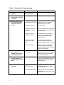
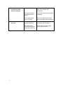
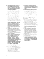
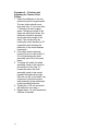
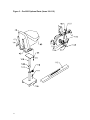
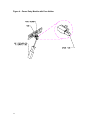
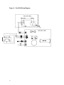
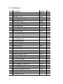
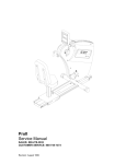
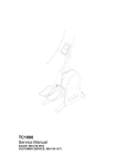
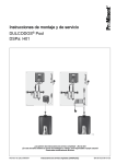
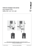
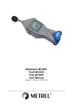
Pro1000
Service Manual
SALES: 800-278-3933
CUSTOMER SERVICE: 800-745-1373
Revision: August 1999
Table of Contents
Section
Page
I.
Overview
2
II.
Troubleshooting Tables
3
III.
Maintenance Procedures
IV.
V.
1
Procedure 1 – Removing the Power Supply
Board
7
Procedure 2 – Checking Voltage at the
Power Supply Board
7
Procedure 3 – Checking and Adjusting the
Speed Sensor
8
Procedure 4 – Removal and Replacement of
the Brake Assembly
8
Procedure 5 – Tightening the Poly-V Belt
9
Procedure 6 – Checking and Adjusting
the Tension in the Chains
Figures
9
Figure 1 – Pro1000 Total Assembly (1-53)
11
Figure 2 – Pro1000 Main Frame (54-99)
12
Figure 3 – Pro1000 Optional Parts (100-112)
13
Figure 4 – Power Entry Module with
Fuse Holder
14
Figure 5 – Pro1000 Wiring Diagram
15
Pro1000 Parts List
16
I. Overview
Purpose.
This manual is designed to assist in service of SCIFIT Pro1000 exercise
machines. The manual is divided into sections to diagnose and isolate problems.
Troubleshooting tables and procedures, along with drawings, are provided to aid
technicians in servicing equipment. The Item Numbers given in the parts list in
Section V can be used to determine the location of various parts in Figures 1-4.
Figures 1-2 show the standard Pro1000. Figure 3 shows an optional hand
crank bar that is adjustable while Figure 4 shows an optional seat assembly that
is vertically adjustable. Be sure to consult the correct figures when servicing
equipment.
When troubleshooting, the actions taken to resolve problems should be
performed in the order stated. Deviating from this sequence may cause damage
to the equipment and lead to unnecessary repairs.
Technical Support.
For further assistance in service of SCIFIT products, please call (800)
745-1373, extension 21. The technical support department is staffed from 8 AM
to 5 PM C.S.T. Monday through Friday. A voicemail service is available 24 hours
daily for recording messages to request technical support and to order
replacement parts.
Please have the following information prior to calling technical support:
•
•
•
•
2
Model number of equipment
Serial number of equipment
Point of contact name and phone number
Detailed description of symptoms encountered.
II. Troubleshooting Tables
Table 1 – Electrical Troubleshooting
Problem
1.1 The machine appears to
be off when plugged in
and switched “on”.
Possible Reasons
Faulty power supply
board (Item 87).
Solutions
If buttons on the control display
beep when pressed, replace power
supply board. See Procedure 1.
Otherwise, check power supply
board. See Procedure 2.
Faulty fuse.
Check and replace fuse if needed.
(See Fig. 4)
Loose cable connection.
Check wire connections at power
supply and display boards.
1.2 Upper control panel
(Item 2) lights are dim.
Power supply board
(Item 87) is faulty.
Replace power supply board. See
Procedure 1.
1.3 Upper board (Item 2)
accepts commands but
rotational resistance
does not change.
Dip switch setting is
incorrect.
Set dip switch to 01.
Power supply board
(Item 87) is faulty.
Check and replace power supply
board as needed. See Procedure 2.
1.4 LED’s on upper board
(Item 2) blinking off/on,
then go dead.
Ribbon cable (Item 6)
connections are loose.
Check and replace accordingly.
Unplug and re-plug machine to
reset.
Faulty power supply
board (Item 87).
Check and replace power supply
board as needed. See Procedure 2.
Display board (Item 2) is
faulty.
Chest strap and
transmitter improperly
worn.
Replace display board.
Loose sensor lead
connection at display
board (Item 2).
Check and adjust as needed.
Faulty receiver.
If there is no audible signal, replace
receiver.
Too many units are
daisy-chained together.
Do not daisy-chain more than 3
units together.
Faulty power supply
board (Item 87).
Check and replace power supply
board as needed. See Procedure 2.
1.5 Heart rate displays zero
(0) in window
1.6 Unit keeps blowing
fuses.
3
Verify that they are being properly
worn.
Ribbon cable connection
is loose (Item 6).
Check cable connection at power
supply and display boards (Items 87
and 2, respectively).
Power cord is loose.
Check and adjust as needed.
Display board is faulty.
Replace display board.
Ribbon cable connection
is loose (Item 6).
Check and adjust cable connection
as needed.
Display board (Item 2) is
faulty.
Replace display board.
1.9 Machine shuts down in
programs but works in
manual.
Display board (Item 2) is
faulty.
Replace display board.
1.10
Can’t select program
or enter information and
no beep when buttons
are pressed.
Overlay/switch panel
(Item 1) is faulty.
Replace overlay/switch panel.
1.7 The upper display (Item
2) resets after starting a
program.
1.8 Program stops, lines of
dots shoot across
screen.
4
Table 2 – Mechanical Troubleshooting
Problem
2.1 Poly-V belt (Item 69) is
slipping.
Possible Reasons
Belt tension is not
adjusted properly.
Solutions
See Procedure 5.
2.2 Excessive free play
exists when the cranks
are turned.
The chain(s) is too loose.
See Procedure 6.
2.3 Machine makes noise
and feels rough when
the hand cranks are
turned.
Bearings (Item 8) in
handle (Item9) are faulty.
Rotate hand cranks about the hand
crank shaft (Item 12). Replace
bearings if source of noise.
Chains are too tight.
See Procedure 6.
Bearings on the hand
crank axles are faulty
(Item 94).
Remove the chains and rotate each
axle separately. Replace bearings if
source of noise.
Bearings in Items 62
and/or 90 are faulty.
With chains and poly-v belt (Item
69) removed, rotate each item
separately. Replace bearings if
source of noise.
Bearings in the brake
assy. (Item 68) are
faulty.
With chains and poly-v belt
removed, rotate the brake assy.
Replace bearings if source of noise.
Freewheel is faulty.
With the chains removed, rotate
each sprocket in the freewheel
direction. Replace if source of noise
and/or rough operation.
2.4 Crank bars (Item 101)
stick and/or slide
roughly into the crank
hub assy. (Item 105).
Crank bars have dents
and/or burrs.
Inspect mating surfaces of crank
bars and hubs for burrs and sharp
edges. Burnish as required with a
fine file or emery cloth.
2.5 Freewheels (Item 64)
make grinding noise,
operate roughly, and/or
stick.
Freewheel is faulty.
Remove the chains and rotate each
sprocket in the freewheel direction.
Replace if source of noise and/or
rough operation.
2.6 Handles lock up while
operating.
Power supply board
(Item 87) is faulty.
Unplug power cord. If handles and
pedals now move freely, replace
power supply board.
Brake (Item 68) is faulty.
If handles do not move with power
cord unplugged, replace brake. See
Procedure 4.
5
2.7 No resistance on
handles and pedals
when in a program.
2.8 Very little resistance at
any level.
6
No speed signal
Check and adjust the speed sensor
(Item 74) as needed. See
Procedure 3.
Wires going to brake
(Item 68) are disconnected.
Check that brake wires are properly
connected.
Power supply board
(Item 87) is faulty.
Check and replace power supply
board as needed. See Procedure 2.
Speed sensor (Item 74)
improperly adjusted.
Check and adjust the speed sensor
as needed. See Procedure 3.
Bad speed sensor
connection with power
supply board (Item 87).
Check voltage at power supply
board. See Procedure 2.
III. Maintenance Procedures
Procedure 1 - Removal and
Reinstallation of the Power Supply
Board
1. Unplug the unit from the power
source.
2. Remove the crank bars and
crank hub assemblies (Items 7 or
105) from the unit.
3. Remove the screws (Item 14)
that fasten the covers (Item 16) to
the main frame. The covers can
be removed now.
4. Locate the power supply cover
(Item 83) on side of unit. Remove
the four (4) screws and remove
the power supply cover. Be
careful when removing the power
supply cover because of the
plastic ties and brake wires.
5. Cut all the plastic ties.
6. Before disconnecting any of the
wires, make note of the wiring
sequence. Refer to the wiring
diagram, Fig. 5.
7. Disconnect the following:
a. The two (2) white (110 V) and
two (2) black (24 V)
transformer wires. These are
all the wires from J4 on Fig. 5.
b. The black and white wires
from the power entry module
– total of two (2). These are
the wires at terminals ACIN1
and ACIN2 on the LCB.
c. The two (2) red brake wires.
d. The one (1) speed sensor
plug – J5 on Fig. 5.
e. The one (1) ribbon cable.
8. The power supply board (Item
87) can now be removed.
Reinstallation is the reverse of
removal.
9. After reinstalling the power
supply board, perform the
7
following procedure to test
correct reinstallation.
a. Plug into power source and
turn on.
b. The message “SCIFIT FOR
SCIENTIFIC SOLUTIONS”
should be scrolling across
upper display board. If not,
see troubleshooting table.
c. Press the start button.
d. Turn the crankshaft in a
forward motion.
e. Verify that values are being
displayed in the rpm/Watt
window.
f. Press the up arrow key to
increase the resistance. It
should become more difficult
to turn the crankshaft. If not,
consult the troubleshooting
table.
g. Press the up arrow and hold
until level 22. After 3-5
seconds of turning, the
resistance should be at its
maximum level. If not refer to
the troubleshooting table. If
brake loaded up to maximum
setting, then the job is
complete.
Procedure 2 - Checking Voltage at
the Power Supply Board
1. Follow steps 1-4 in Procedure 1.
2. Disconnect the speed sensor
from the lower supply board at
the J5 terminal. See Fig. 5. Use a
voltmeter to measure the DC
voltage across the speed sensor
pins on the power supply board.
Measure the voltage across the
pin with the red wire (+) and
either one of the center pins (-).
The voltmeter should measure 45 volts DC.
3. If there is no voltage, replace the
power supply board. See
Procedure 1.
Procedure 3 – Checking and
Adjusting the Speed Sensor
1. Turn machine on and press start.
2. Turn crank arms (Item 7 or 101)
at 1 revolution per second. The
RPM window should display
around 60 ±10 rpm.
3. If the RPM window is displaying a
reading outside of the specified
range, proceed to the next step to
adjust the speed sensor.
4. Remove the crank arms and
cover (Item 7 or 105 and Item 16)
from the right side of the
machine.
5. The air gap between the brake
flywheel and speed sensor
should be 1/8” – 3/16”.
6. The speed sensor must be
pointed directly at the flywheel so
the eyes of the sensor will
intersect the center of the axis of
the brake. Adjust as needed.
7. Rotate the crank arm again at 1
rev. per second. If the RPM
window displays a number
greater than zero (0) but not
within 60 ±10 rpm, repeat Steps 1
- 7. If a reading of zero (0) is
displayed, proceed to step 8.
8. Use a voltmeter to measure the
DC voltage across J5 pin 1 (+)
and J5 pin 2 (-) on the power
supply board. Refer to Fig. 5. The
voltmeter should read 4-5 VDC.
9. If there is no voltage, replace the
power supply board (Item 87);
8
see Procedure 1. If 4-5 volts are
present, replace the speed
sensor.
Procedure 4 – Removal and
Replacement of the Brake
Assembly
1. Remove all the crank bars (Items
8 and 53) and crank hub
assemblies (Item 55) from the
unit.
2. Remove the screws (Item 15)
that fasten the covers (Items 17
and 59) to the main frame. The
covers can be removed now.
3. Disconnect the two red wires on
the right side of brake (Item 73).
4. Relieve the tension in the poly-v
belt (Item 74) by loosening the ½20 nut attached to item 62.
Loosen the set screw (Item 72). If
the pulley brake drive shaft does
not move on its own, use a
hammer to knock the shaft back
a few millimeters.
5. Remove the poly-v belt from the
plastic pulley by wedging a
screwdriver blade between the
belt and pulley while rotating the
brake slowly downward to work
the belt off the pulley. Take care
not to damage the pulley.
6. Remove the three (3) socket
head screws (Item 61) that hold
the brake assembly to the main
frame.
7. Pull brake away from main frame.
Be careful not to damage the
speed sensor when removing the
brake.
8. Remove the brake from the
machine and set aside to return
to SCIFIT (request a UPS call tag
by phone).
9. Reinstallation is the reverse of
removal. Before tightening the
tension in the poly-v belt, make
sure that it is centered correctly.
If misaligned, wedge a
screwdriver blade between the
face of the brake and the belt
while turning assembly to align
belt to center of idler pulley.
10. After brake assembly has been
aligned and tension set, attach
speed sensor tape (Item 71) to
the left edge of the brake
armature. First peel off tape
backing on the end with the wide
silver band and stick on the brake
surface hanging down. The tape
should be on center with the
speed sensor. Slowly rotate the
brake upward and wrap tape
around the circumference of the
brake.
11. Temporarily install the crank
hub/bar assembly. Perform the
following steps 12 through 16 and
perform the alignment,
(Procedure 3), if indicated results
are not attainable.
12. Plug in and turn on machine but
don’t press any buttons. The
display will be scrolling the
message, “SCIFIT…” Slowly
rotate the crank arm assembly
and the message will change to a
programming prompt. The
following values will be displayed:
[20.00] in TIME, [0] in RPM, and
[4] in LEVEL. If the display
doesn’t default to these values,
perform Procedure 3.
13. Press the START/STOP button
once and press the SCAN/HOLD
button to hold the RPM function.
Press and hold the DOWN
ADJUST arrow until 0.0 is
displayed in the LEVEL window.
9
14. Rotate the crank arms at one
revolution per second and ensure
display accurately reads about 60
RPM.
15. Press and hold the UP ADJUST
arrow button to the maximum,
level 22. Rotate the crank arms
as rapidly as possible. Brake
resistance should become
increasingly difficult momentarily.
Procedure 5 – Tightening the
Poly-V Belt
1. Loosen the ½-20 nut that fastens
the brake drive pulley shaft (Item
57) to the main frame.
2. With the nut still on the shaft, use
a hammer to knock the entire
brake drive pulley assembly away
from the brake assembly (Item
68).
3. After knocking the brake drive
pulley shaft a few millimeters
away from the brake assembly,
tighten the set screw (Item 67) so
that it butts up to the brake drive
pulley shaft.
4. Tighten the ½-20 nut that holds
the pulley shaft.
5. Check that job is complete by
rotating crank handles. If there is
no noise due to belt slippage, the
job is complete. If noise persists,
return to step 1.
Procedure 6 – Checking and
Adjusting the Tension in the
Chains
1. Check the deflection in the two
chains along their longest spans.
The two chains should never
have less than ¼” nor more than
1” deflection at their longest
spans. Since some parts of the
chain are stiffer than others, the
deflection should be checked
across the entire length of the
chain. This can be done by
rotating the crank handles in 45°
increments and checking the
deflection of the chain between
increments.
2. If the chain needs adjusting,
loosen but do not remove the ½20 nut that fastens the shaft
assembly (Item 90) to the main
frame.
3. To tighten the chain, the shaft
assembly needs to be moved in
the direction of the seat. To
loosen the chain, the shaft
assembly needs to be moved
towards the brake drive pulley.
With the nut still on the shaft, use
a hammer to knock the entire
shaft assembly a few millimeters
in the prescribed direction.
4. Tighten the ½-20 nut and check
the deflection as in step 1.
5. Repeat steps 1-4 until the desired
stiffness is reached.
10
IV. Figures
Figure 1 – Pro1000 Total Assembly (Items 1-53)
11
Figure 2 – Pro1000 Main Frame (Items 54-99)
12
Figure 3 – Pro1000 Optional Parts (Items 100-112)
13
Figure 4 – Power Entry Module with Fuse Holder
14
Figure 5 – Pro1000 Wiring Diagram
15
V. Pro II Parts List
Item Description
1 overlay/switch panel
2 Display board
3 standoffs, 1", 6-32
4 Console
5 screw, 6-32x.5, b.h., blk.
6 cable, ribbon, assy
7 hub, crank, fixed, long, machine
8 bearing, flanged, 5/8 dia., igus
9 handle, handcrank
10 washer, 5/8, plastic
11 ring, snap, retainer, 5/8
12 shaft, crank, hand
13 washer, cover, plastic, black
14 screw, 1/4-20x1.25, black, b.h., socket cap
15 decal, body, Pro 1000
16 cover, right, gray, dull
cover, left, gray, dull
17 decal, serial number
18 nut, 5/16-18, blk.
19 lockwasher, 5/16, blk.
20 wheel, front, pro II
21 bolt, 5/16-18 x 1.75, blk.
22 bolt, 3/4-18x6, blk.
23 decal, UL certification
24 base, Pro II
25 extrusion, rail, roller, seat
26 nut, pan, 5/16-18
27 lockwashers, 5/16, pltd.
28 bolt, 5/16-18 x 3, pltd.
29 seat base, Pro1000, wldmnt&plate
30 screw, 5/16-18, p.h., black
31 roller, urethane, 1 1/4 dia. X 3/8
32 nuts, lock, 5/16 -18 pltd.
33 screw, 10-32x.5, black, b.h., socket cap
34 rod, lock, pos., seat, PRO1000
35 pin, clevis, 1/4x1"
36 brkt., pos., adj., lever
37 pin, carter, 3/32 x 3/4
16
Part No.
65112
65110
P1051
65202
65120
66325M
P1173
67356
67306
65024
65201RG2
65200LG2
70400
70396
A1030
P1059
C1122
P1038
P1062
A1121
A1115
Qty.
1
1
10
1
4
1
2
4
2
4
2
2
12
16
2
1
1
2
2
2
2
2
2
1
1
2
12
12
12
1
18
18
18
9
1
2
1
2
38 brkt., pivot, rod, lock
39 spring
40 frame, seat
41 lockwasher, 1/4, blk.
42 seat pad (back)
43 seat pad (bottom)
44 lockwasher, 1/4, pltd.
45 bolt, 1/4-20x1.25, pltd.
46 bracket, spring
47 sticker, track adjustment
48 track, adjustment, seat, stainless steel, Pro1000
49 decal, manufacturing date
50 endcap, 3"dia
51 screw, M5x1.0x25, s.h., blk.
52 manual, operator's
53 cord, power, 110V, 9'10"
54 frame, main
55 screw, 10-32x.75, s.h., blk.
56 lockwasher, #10, pltd.
57 shaft, brake, drive, pulley
58 bolt, M5x.8x19, socket cap
59 ring, snap, retainer, 1/2
60 bearing, hub, brake drive
61 lockwasher, #8, pltd.
62 hub, brake drive pulley, hubed
63 pulley, brake drive
64 freewheel, Pro II, shimano
65 0.020" and 0.035" shims
66 tape, pickup, speed
67 bolt, 8-36x1.188, blk.
68 brake, assy.
69 belt, brake, poly-v
70 channel, transformer
71 screws, 4-40x.5 p.h. pltd.
72 washer, #4, split, pltd.
73 washer, #4, flat, pltd.
74 sensor, speed, assy.
75 transformer, 24V, 5.4 A
76 bracket, speed sensor
77 screw, M4x.7x10, s.h., blk.
78 washer, M4, pltd.
17
A1119
71385
71101
71100
P1056
A1120
A1114
70330
65169
69321
68312-2
68012
68316-2
68313
68013
65141
68000
68014
A1359
65140
65180
69403
1
1
2
4
1
1
4
4
1
1
1
1
2
16
1
1
1
3
3
1
3
1
2
11
1
1
4
NA
1
1
1
1
1
1
1
1
1
1
1
4
4
79 nut, M4x.7, pltd.
80 p.e.m., recep for daisychain
81 module, power entry, RF/EFI
82 screw, 3/16-32x3/8, p.h.
83 cover, supply, power
84 starwasher, #6
85 screw, 6-32x3/8, p.h.
86 standoffs, 3", 6-32
87 power supply, (lower), serial
88 clip, u-type
89 shell, bearing, crank hub
90 hub, brake drive pulley, nohub
shaft, brake, drive, pulley
bearing, hub, brake drive
ring, snap, retainer, 1/2
91 mount, hub, sleeve, sprocket, wide
92 board, heartrate, PCB
93 nut, 5/16-18, pltd.
94 axle, long, top
bearing, axle
nut, M2x1.5
shell, bearing, crank hub
ring, snap, retainer, 1
95 cotter pin, 9mm
96 mount, hub, sleeve, wide
97 lockwasher, 5/16, pltd.
98 bolt, 5/16-18x2.5, pltd.
99 bolt, 3/8-24x2.75, pltd.
100 screw, M6x1.0x25, s.h.
101 bar, hand crank
102 roll pin, 3/16x1/2
103 screw, M5x.8x12, b.h., blk.
104 cover, crank hub
105 hub, crank, assy.
106 seatbase, ProII, weldment
107 spring, gas
108 adapter, gas shock, seat, sq.
109 extension, seatbase, ProII, weldmnt.
110 pin, popper, turn to release
111 plunger, adjust, seat height
112 track, adjustment, stainless
18
65177
65178
A1043
65150S
Sin0407
68316-1
68312-2
68012
66355-1
65160
66370L
66370B
Sin0407
66372
66354-1
66311
66304
A1364
C1168
P1177
A1166
C1169
P1223
71200
71395
4
1
1
1
1
8
8
4
1
12
1
1
1
2
1
1
1
6
1
2
2
1
2
2
1
6
6
4
2
2
1
16
2
2
1
1
1
1
1
1
1